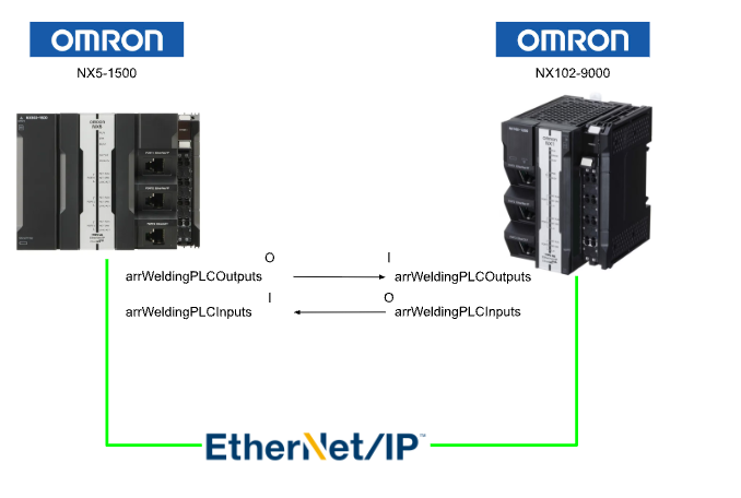
In this article, we explain how to set up EtherNet/IP communication between OMRON NX CPUs.
Now, let’s enjoy FA!
Tag Data Link
Tag data links enable periodic tag data exchange over an EtherNet/IP network between controllers or between a controller and other devices. Variables are assigned to tags.
In communication between controllers, connection information is set on the built-in EtherNet/IP port of the controller (originator) that receives (consumes) data.
The output words and input words of each node exchanging data must be set in the connection information. These words are called the output tag set and input tag set, respectively. Each tag set must contain at least one tag.
In addition, the data size for data exchange is the total size of tags included in the tag set, and the size of the output tag set must match the size of the input tag set.
Tag Sets
When a data link connection is established, one or more tags (up to 8 tags including controller status) are set as a tag set for the connection. This is called a tag set. Each tag set represents a data unit of one tag data link connection.
Therefore, a tag data link is created by establishing a connection between one tag set and another tag set. Also, a tag set name must be configured for each tag set.
Usage Example
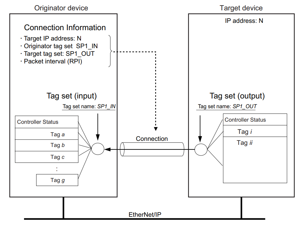
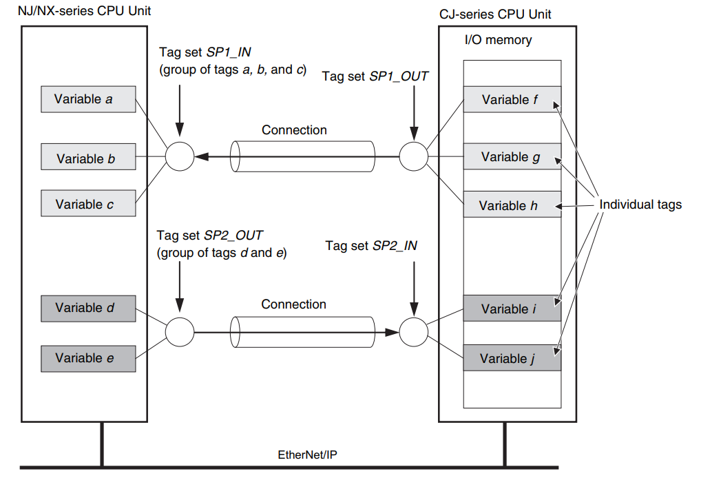
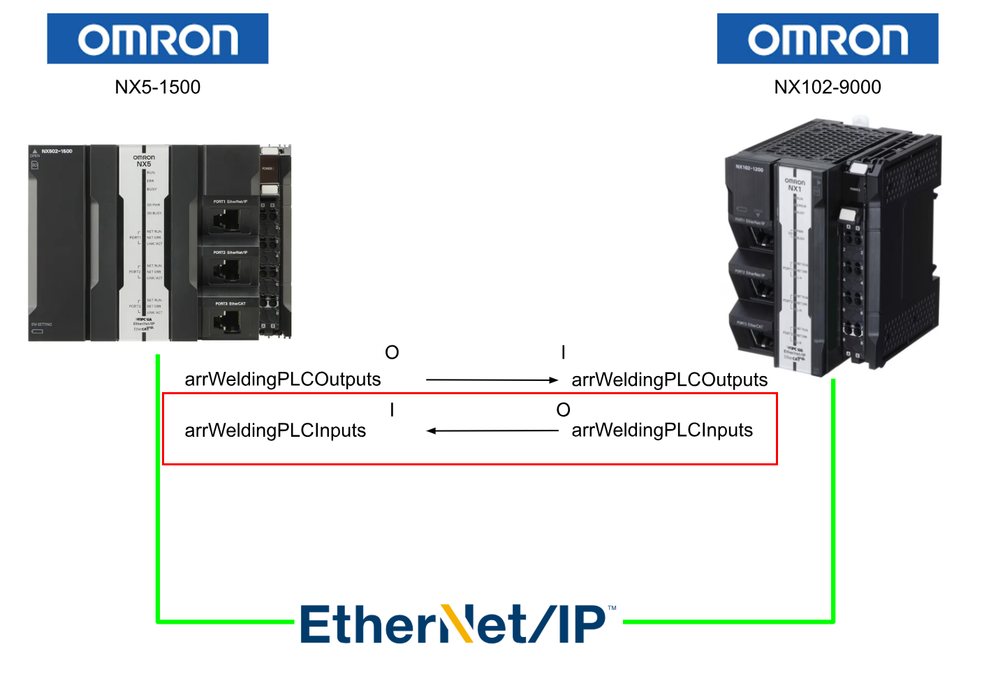
In the following example, the input tags “a” to “g” on the originator side form a tag set called SP1_IN, and the output tags “i” and “ii” form a tag set called SP1_OUT. A connection is set up between these two tag sets.
There are input (consume) tag sets and output (produce) tag sets. Each tag set can contain either input tags or output tags. However, the same input tag cannot be included in multiple input tag sets.
Number of Tags per Tag Set
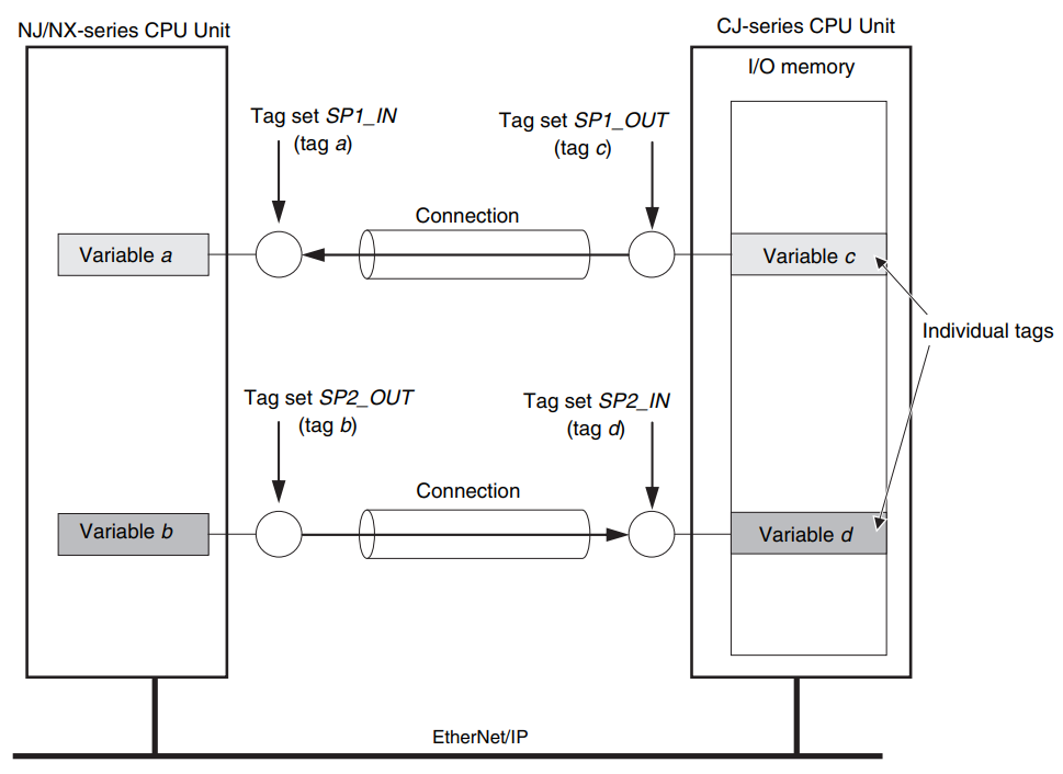
For one connection, one or more tags can be set in each input and output tag set. For example, you can set one tag in the input tag set and multiple tags in the output tag set.
Tag Sets with Multiple Tags
Note that the number of tags that can be grouped depends on the CPU you are using.
- In the NX701 CPU unit, up to 8 tags (total maximum of 722 words) can be allocated to a single tag set.
- In the NX50202 CPU unit, up to 64 tags (total maximum of 722 words) can be allocated to a single tag set.
- In the NX10202 CPU unit, NX102P2 CPU unit, and NJ-series CPU units, up to 8 tags (total maximum of 300 words) can be allocated to a single tag set.
Note that when enabling a connection, each tag set must contain only input tags or only output tags. (A single tag set cannot contain both input and output tags).
Connection Setting Parameters
EtherNet/IP connection settings include the following configuration parameters.
Requested Packet Interval (RPI) Settings
RPI (Requested Packet Interval) is the I/O data refresh cycle on the EtherNet line when a tag data link is established. In EtherNet/IP, data is exchanged on the communication line at the RPI set for each connection, regardless of the number of nodes. With the built-in EtherNet/IP port, you can set the RPI for each connection.
Multicast or Unicast Communication Settings
In tag data link connection settings, you can select either a multicast connection or a unicast (point-to-point) connection as the connection type. By sending one output tag set to multiple nodes, multicast connection can reduce communication load.
Multicast Connection
In a multicast connection, an output tag set can be transmitted to multiple nodes in a single packet and assigned to input tag sets.
Unicast Connection
A unicast connection sends one output tag set individually to each node.
It transmits as many packets as the number of input tag sets.
Tag Data Link Data Concurrency
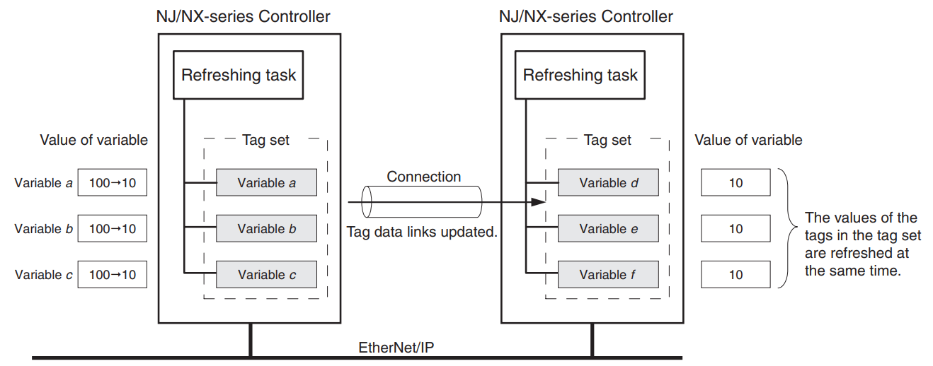
To maintain data concurrency in tag data links, a refresh task must be configured for each network variable assigned to a tag.
- Maintain concurrency of tag data within a tag set.
- Synchronize the timing of updating network variables assigned to tags with the execution period of programs accessing those network variables.
To maintain concurrency among values of multiple tags within a tag set, tags (variables with the Network Publish attribute) must satisfy all of the following conditions:
- Tags must be assigned to the same tag set (connection).
- A refresh task must be configured for the network variables assigned to tags, and the same refresh task must be set for all tags in the tag set.
- For NX50202, NX102, NX102P2, and NJ-series CPU units, do not include AT-specified tags in tag sets.
- The variable access time set for each task must be set larger than the value required for tag data transfer.
- Tag update task settings (network variables) maintain concurrency of tags within tag sets.
Implementation
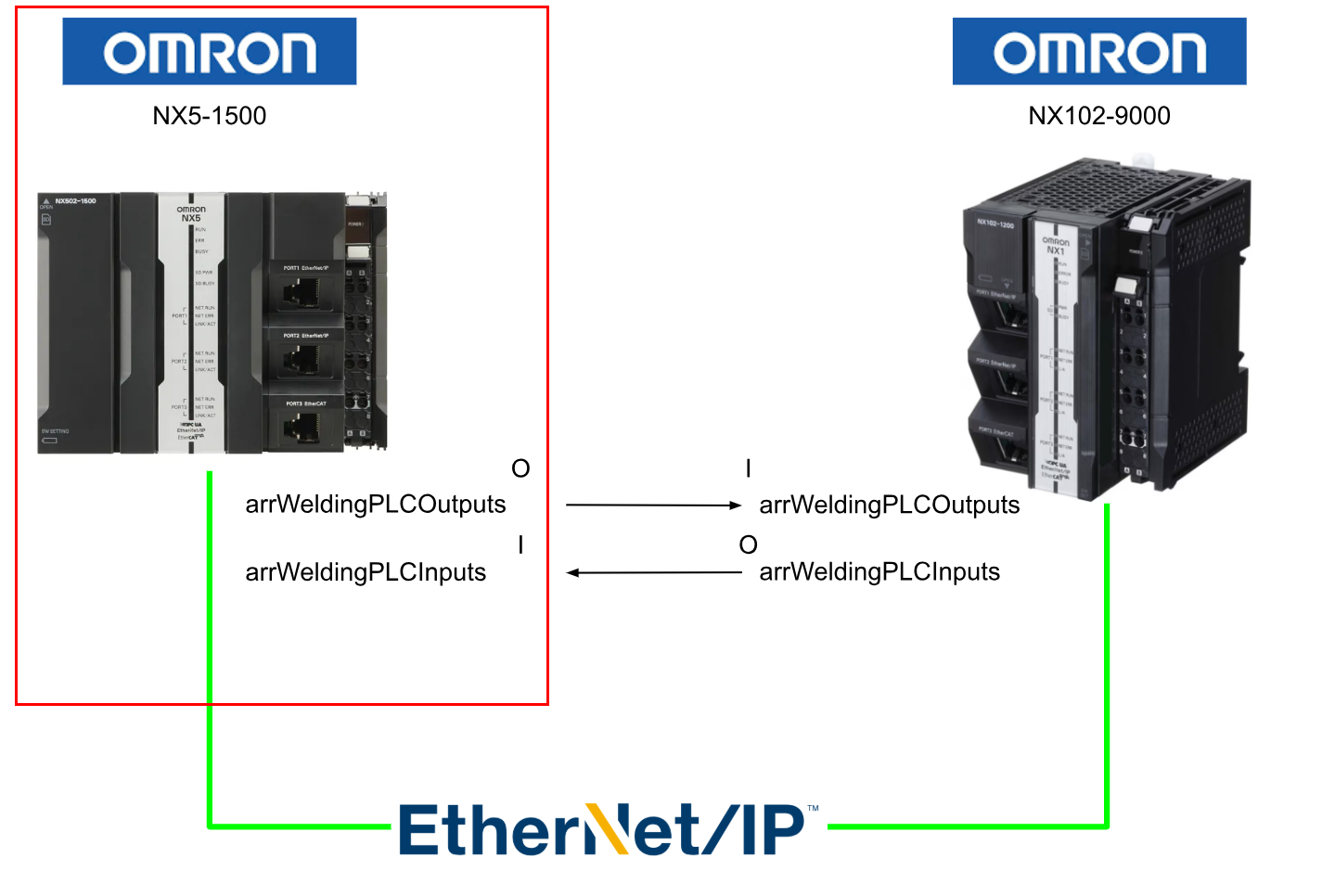
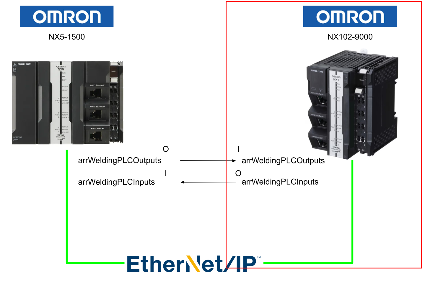
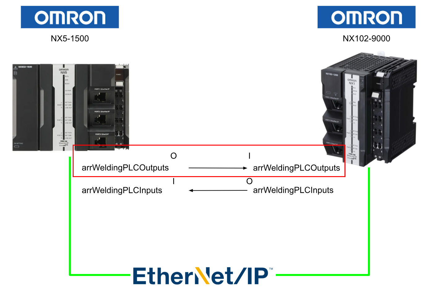
In this article, configuration is required for both NX102-9000 and NX502-1500.
NX502 Side
First, configure the NX502-1500 side.
Initial Login
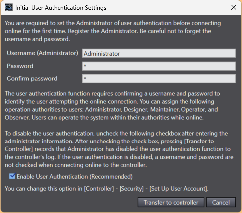
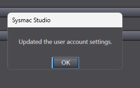
When connecting a new NX502-1500 from Sysmac Studio, you will be prompted to set a user name and password. Set them up and transfer them to the CPU.
Done!
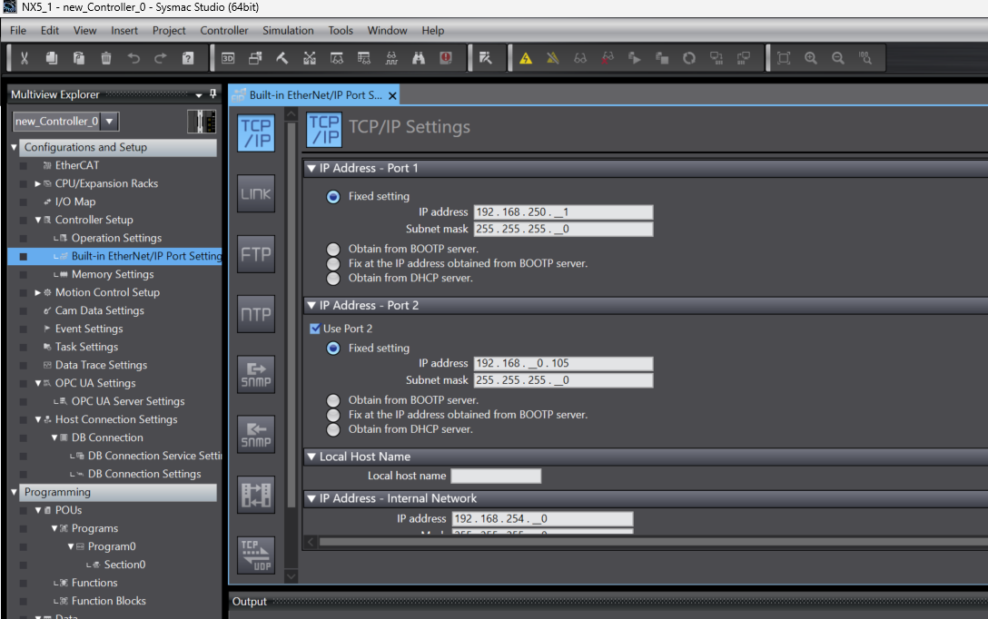
EtherNet/IP Port
Next, configure the IP settings for the EtherNet/IP Port on the NX502-1500 itself.
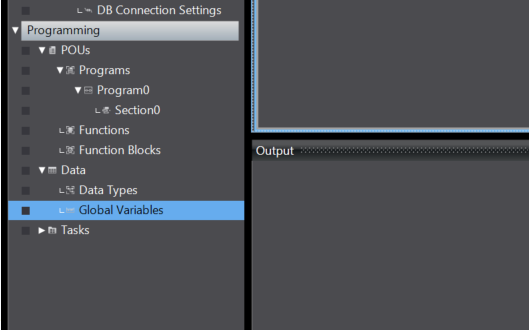
Defining Global Variables
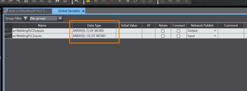
Define variables in Programming > Global Variables.
Define word arrays of lengths 8 and 16, and set them as Input and Output respectively.
EtherNet/IP Settings
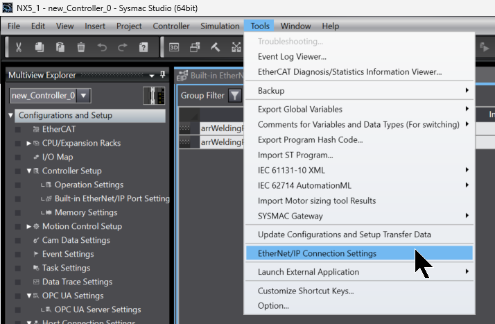
Next, configure the EtherNet/IP connection for NX502-1500 by clicking Tools > EtherNet/IP Connection Settings.
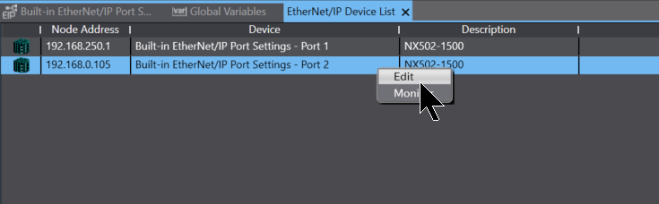
In this article, Port 2 is used, so right-click Port 2 > Edit.
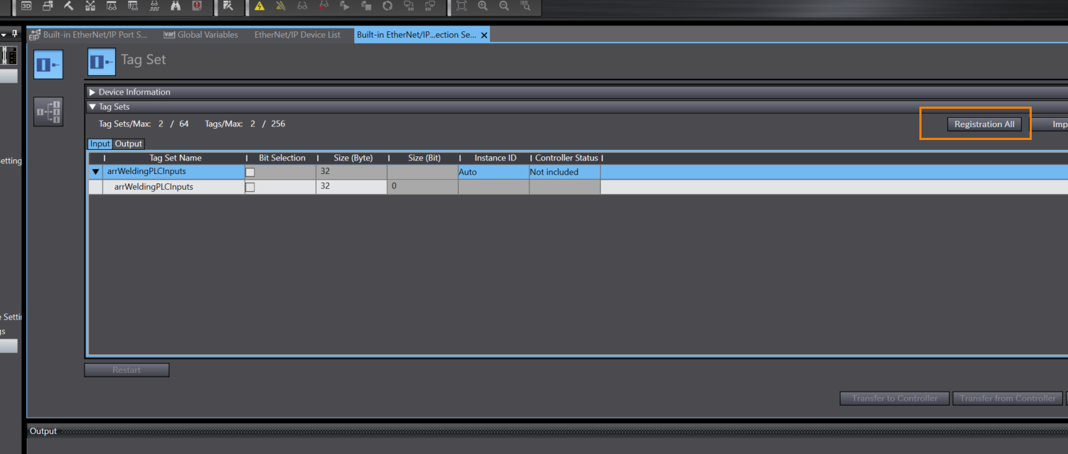
Register All Variables
Register the Input/Output variables from the program to the EtherNet/IP network using the “Registration All” button.
Adding NX102-9000
Next, add the NX102-9000 EtherNet/IP connection to Sysmac Studio.
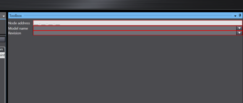
Node Address
Set Node Address to the IP address of the NX102-9000.
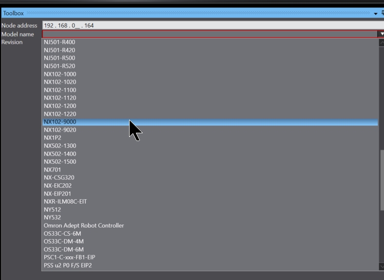
Model Name
Set Model Name to NX10202-9000.
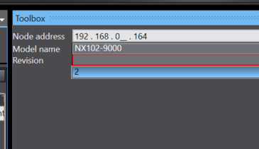
Revision
Set Revision to 2.
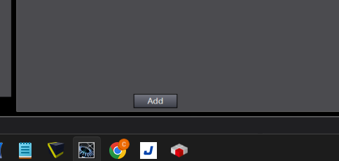
Result
Finally, click the Add button to add NX10202-9000.
Done!
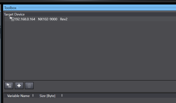
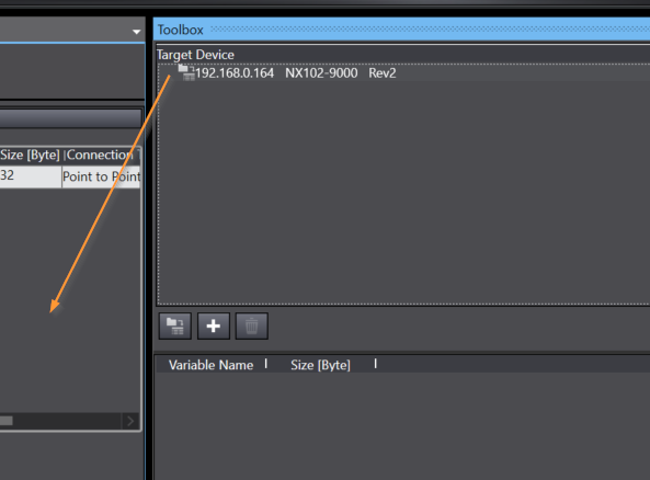
Insertion into EtherNet/IP Network
Add the newly added NX10202-9000 to the EtherNet/IP network.
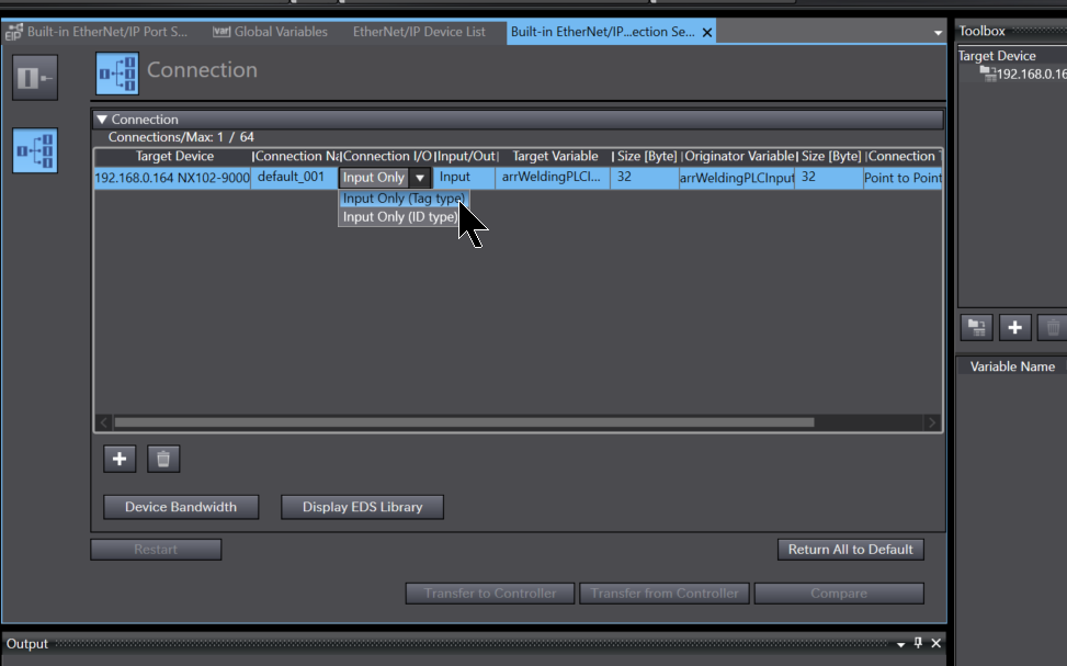
Connection I/O
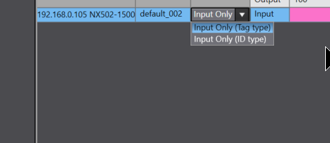
Since Tag communication is used in this article, set Connection I/O to Input Only (Tag Type).
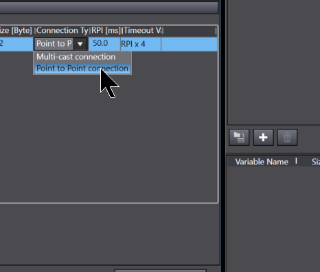
Connection Type
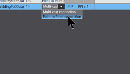
Set Connection Type to Point to Point Connection.
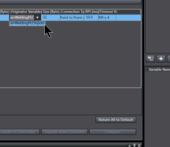
Originator Variable
Define this using the variable registered earlier.
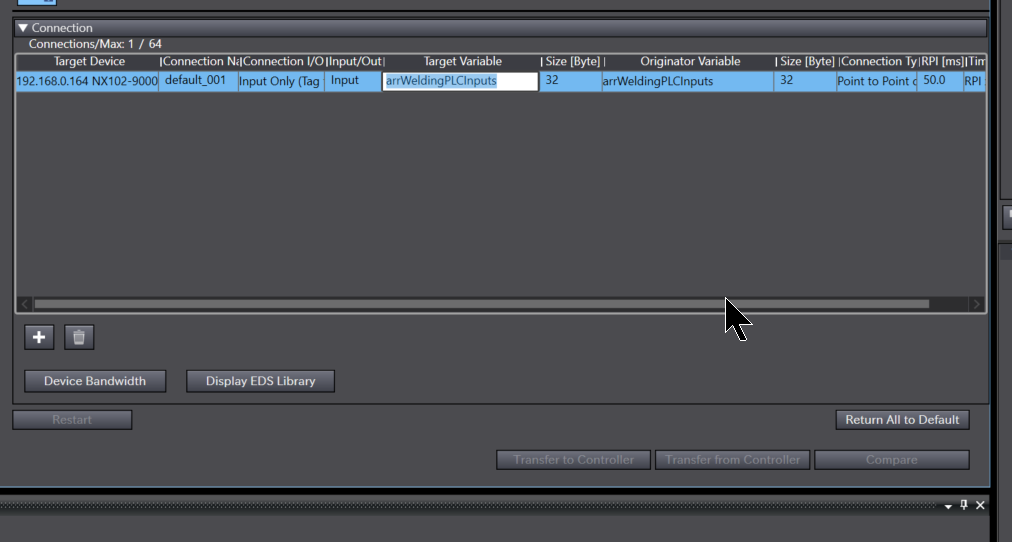
Target Variable
In this field, set the Tag name of the NX102-9000 (the target side) so that it matches.
Result
This completes the EtherNet/IP connection setup from NX102-9000 to NX502-1500.
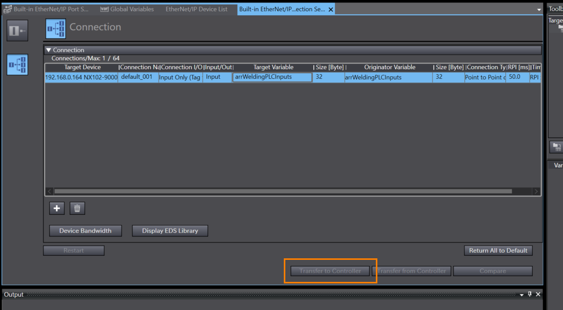
Transfer to Controller
After completing the EtherNet/IP settings, transfer the EtherNet/IP configuration to the NX502-1500 using Transfer to Controller.
Download
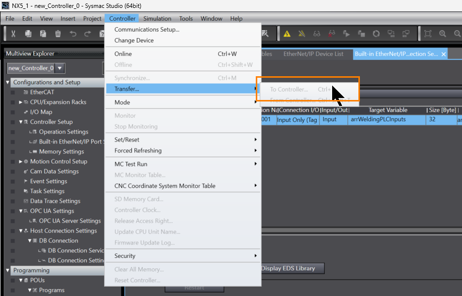
Next, transfer the entire project to the NX502-1500 via Transfer > To Controller.
NX102 Side
Next, let’s move on to the NX102-9000 side.
EtherNet/IP Port
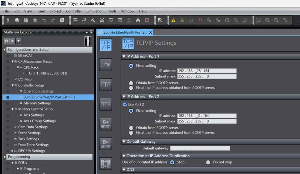
Configure the IP settings for the EtherNet/IP Port on the NX102-9000 itself.
Defining Global Variables
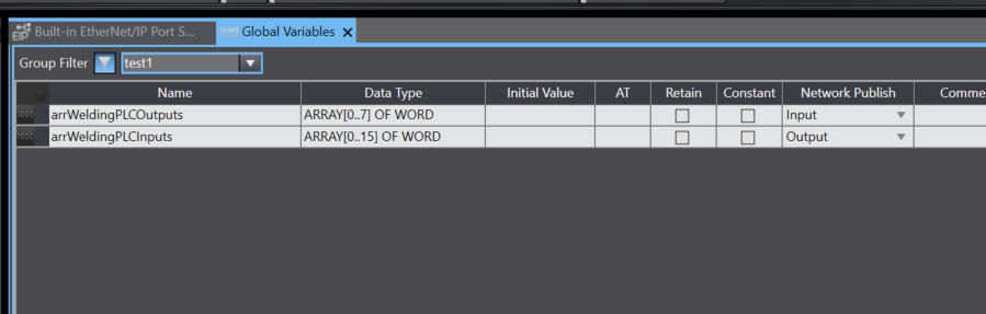
Define variables in Programming > Global Variables.
EtherNet/IP Settings
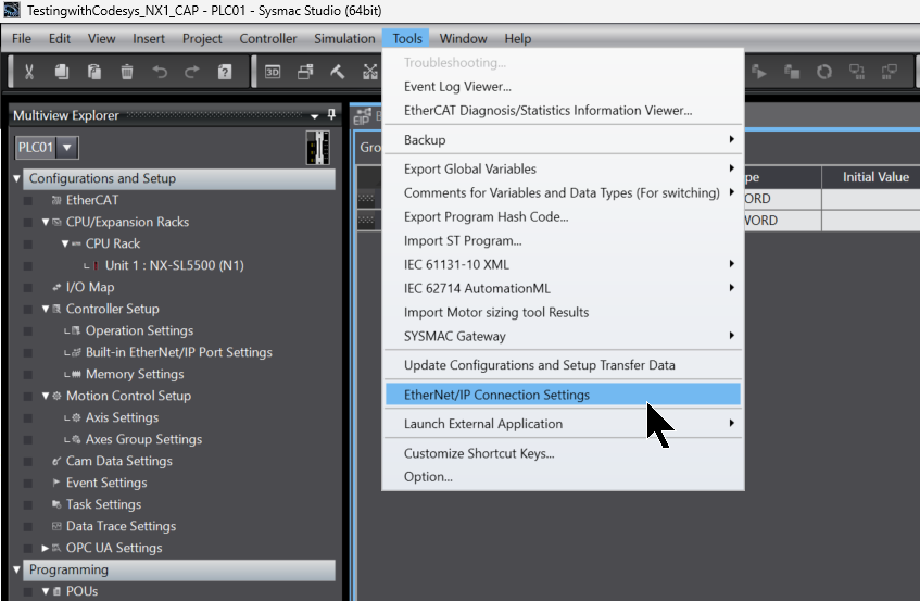
Next, configure the EtherNet/IP connection for NX102-9000 by clicking Tools > EtherNet/IP Connection Settings.
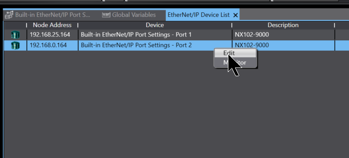
In this article, Port 2 of NX102-9000 is used, so select Port 2 > right-click > Edit.
Register All Variables
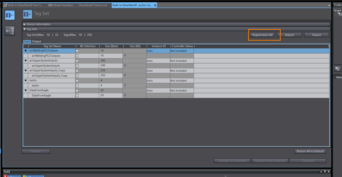
Register the Input/Output variables from the program to the EtherNet/IP network using the “Registration All” button.
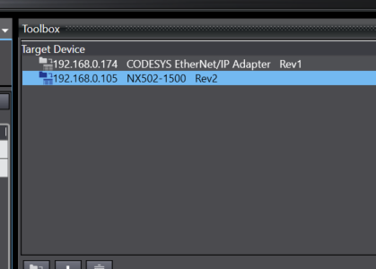
Adding NX502-1500
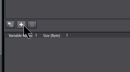
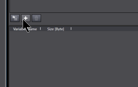
This time, to add NX502-1500 to the project, click the + button in the Toolbox on the right side.
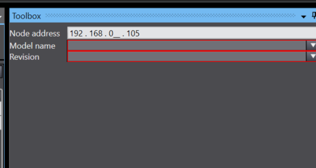
Node Address
Set Node Address to the address of the NX502-1500.
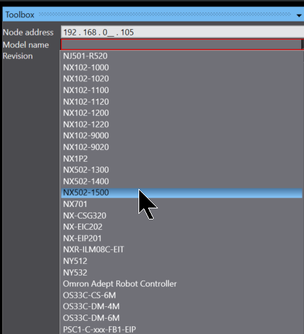
Model Name
Set Model Name to NX50202-1500.
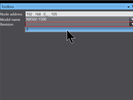
Revision
Set Revision to 2.
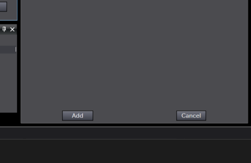
Result
Finally, click the Add button to add NX50202-1500.
Done!
Insertion into EtherNet/IP Network
Add the NX50202-1500 to the EtherNet/IP network of the NX102-9000.
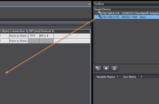
Done!
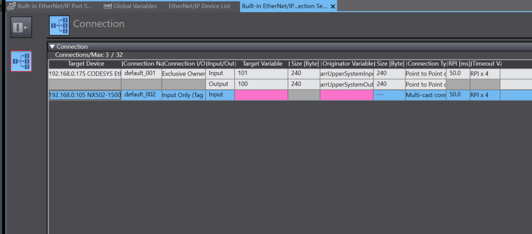
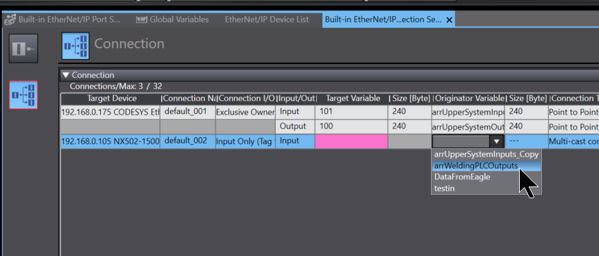
Originator
Set Originator Variable to the variable registered earlier.
Point to Point Connection
The connection type can be Point to Point.
Connection I/O
Since Tag communication is performed here, set Connection I/O to Input Only (Tag Type).
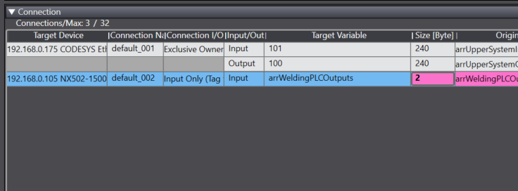
Size (Byte)
Set Size the same as the Originator variable.
Result
Done!
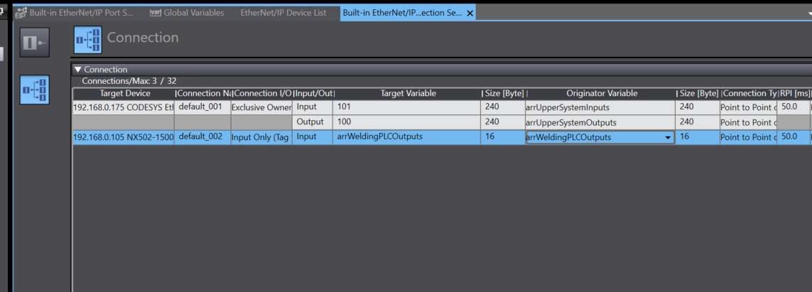
This completes the EtherNet/IP connection setup from NX502-1500 to NX102-9000.
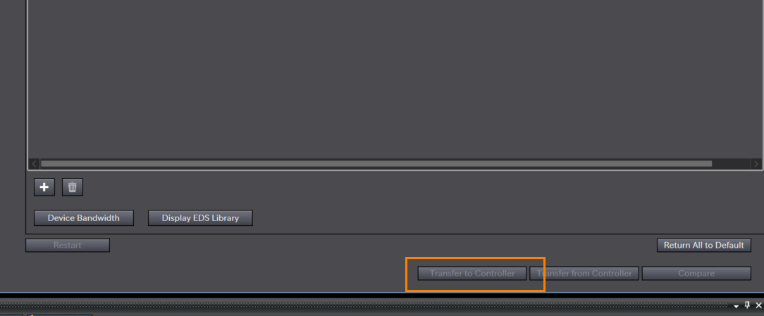
Transfer to Controller
After completing the EtherNet/IP settings, transfer the EtherNet/IP configuration to the NX102-9000 using Transfer to Controller.
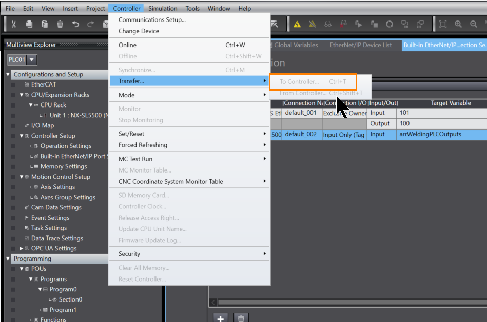
Download
Next, transfer the entire project to the NX102-9000 via Transfer > To Controller.
Result
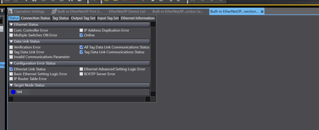
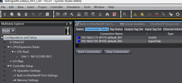
To verify the EtherNet/IP connection in Sysmac Studio, right-click the corresponding Port > Monitor.
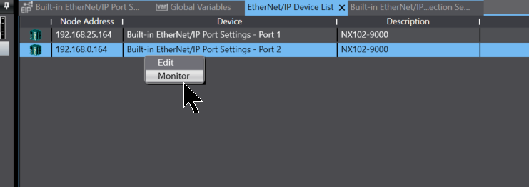
Done!
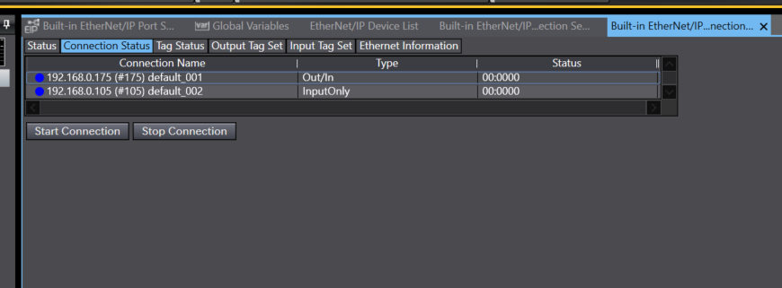
Also, a blue indicator light at 164 shows normal communication with the device at IP address 64.
Write new data on the NX502-1500 side.
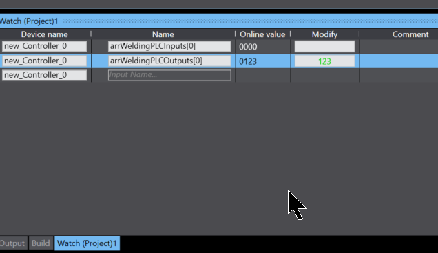
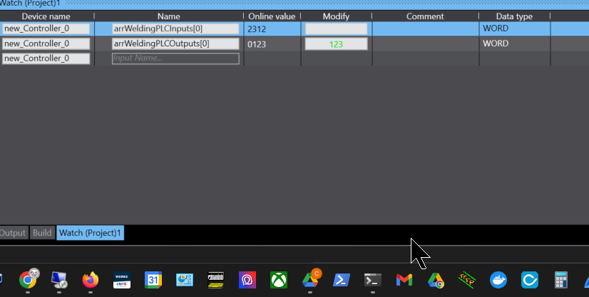
Done! Data was correctly received on the NX102-9000 side.
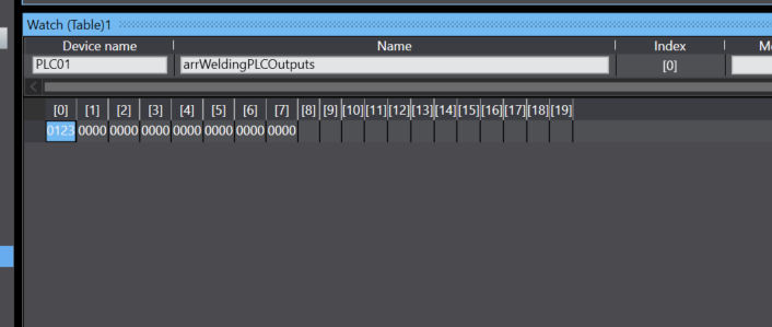
Next, let’s check the NX102-9000 side as well.
Change the output data on the NX102-9000 side.
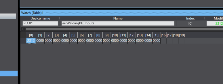
Done! Data was successfully received from the NX50202-1500 side as well!