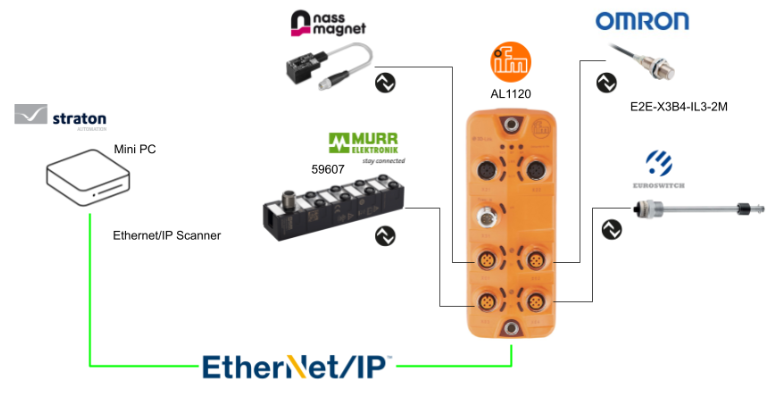
こちらは新しいシリーズの記事で、StratonというSoftware PLCを使って様々なテストを展開します。今回はStraton RuntimeにEthernet/IP Scannerを立ち上げ、EDS FileからIFM AL1120とEthernet/IPネットワークを構築します。
さ、FAを楽しもう。
Reference Link
http://soup01.com/ja/category/straton/
前書き
いつも私の技術ブログとYouTubeチャンネルをご覧いただき、心より感謝申し上げます。また、いまFullさん(full@桜 八重 (@fulhause) / X)と共に毎週水曜日の夜にお届けしている「高橋クリス」ラジオ番組を運営しています。
現在、私達の活動はほぼ無償で続けており、より多くのコンテンツを提供するためには、皆様の温かいご支援が大変重要です。もし可能であれば、以下のリンクから応援していただけると大変嬉しく思います。
高橋クリスのメンバーシップ
こちらはFullさん(full@桜 八重 (@fulhause) / X)と共にやっているラジオにメンバーシップを登録いただけます。
https://note.com/fulhause/membership/join
AMAZON ギフトリスト
こちらは自分のブログのコンテンツ制作や設備の充実に大いに役立てさせていただきます。
https://www.amazon.co.jp/hz/wishlist/ls/H7W3RRD7C5QG?ref_=wl_share
Patreon
こちらは自分のブログのコンテンツ制作や設備の充実に対する小さな応援の気持ちのPatreonです。
https://www.patreon.com/user?u=84249391
皆様のサポートが、私たちの活動をより充実させる力となります。
どうぞよろしくお願いします。
メールアドレス(*=@)
X
SerializeIn?
こちらはByte配列から変数の値を取り出すための関数になります。

VAR_INPUT
| 変数名 | データタイプ | 説明 |
| FRAME | USINT | ソースバッファ – 配列 |
| DATA | ANY(STRING以外) | コピー先の変数 |
| POS | DINT | ソースバッファ内の位置 |
| BIGENDIAN | BOOL | TRUE=フレームがビッグエンディアン形式でエンコードされていること |
VAR_OUTPUT
| 変数名 | データタイプ | 説明 |
| NEXTPOS | DINT | 抽出されたデータの後のソースバッファ内の位置。エラー(無効な位置/バッファサイズ)の場合は0になります。 |
Implementation
これからプログラムを作成しましょう。
IFM Side
まずはIFM AL1120から始めます。

Download EDS File
こちらのLinkでIFM AL1120のIOLINK Master EDS FileをDownloadしてください。
https://www.ifm.com/jp/ja/product/AL1120#documents

Assign IP Address
次はIFM AL1120にIPアドレスを割り付けます。今回はMolex社のEthernet/IP ツールを使用します。StationをAL1120に設定し、Snd List Identity Request on UDPをクリックし、ネットワークのデバイスを検索しましょう。

0xF5 TCP/IP Tabを開き、Attr 5にIPアドレスを設定し>Set Attributeで設定を転送します。

そのあとはGet_Attribute_allで設定を確認しましょう。

straton Side
次はstraton側を構築します。

Fieldbus Configuration
STRATON ツールからEthernet/IP Scanner接続を追加するために、Insert> Insert Configurationをクリックします。

Ethernet/IP(ODVA)>Ethernet/IP I/O Scanner(Client)を選びます。

Our IP addressはStraton RuntimeがインストールされたデバイスのIPになります。

Import EDS File
次は先程追加したEthernet/IP Scannerを選び>Import EDS Fileをクリックします。

IFM HPからDownloadしたEDS FileをImportします。

Done!EDS FileがImportされ、そのEDS Fileに記述されたConnectionをこの画面で設定できるようになります。

Configure Connection
ConnectionのDrop-Down listから接続タイプを設定します。今回の記事ではExclusive Owner IOにします。

Input(Target to Originator)のDrop-Down listから接続するAssembly を設定できます。

今回の記事ではAssembly 102を使用します。該当するAssemblyを選択するとInstance番号とデータサイズもEDS Fileに記述された設定に自動入力されます。
そして同じ操作でOutptus(Originator to Target)をAssembly 150に設定し、Okで進みます。

Yesで進みます。

Done!それでIFMのAL1120をEthernet/IP ネットワークに追加しました。

Configuration Assembly
次はIFM AL1120とSTRATON RUNTIMEをEthernet/IP で接続するにはConfiguration Instanceを設定する必要があり、先程追加したEthernet/IP Adpaterをクリックします。

Configuration>instanceを199に設定します。

AL1120の取説にはConfiguration Assemby番号が199であることが記述されました。

次はConfiguration Assembyのデータを設定します。

Access Right
Byte0はAccess Rightであり、該当するIO-Linkマスターの稼働モードを設定します。今回の記事では0x01(Ethernet/IP+IoT)を使用します。
Process data length
Byte1️1はAccess Rightであり、該当するIO-LinkマスターのProcess Data長さを設定します。今回の記事では0x03(16Bytes入出力)を使用します。
Port Mode
Port1-4の設定も同じなので、ここでPort1Byte1️1はAccess Rightであり、該当するIO-LinkマスターのProcess Data長さを設定します。今回の記事では0x03(16Bytes入出力)を使用します。
STプログラムにArrayINとArrayOutというByte配列を定義します。

Mapping
AL1120とデータ交換する変数を定義するためにInsert Variableをクリックします。

Symbolをクリックします。

先程定義したByte配列と繋がります。

該当する変数のByte Offsetとデータタイプも設定します。

Done!

Program
こちらはStratonで作成したプログラムです。
| //IFM IO Link Master Pin4 status tempByte:=arrayIN[0]; xIFMDIX01Pin4:=tempByte.0; xIFMDIX02Pin4:=tempByte.1; xIFMDIX03Pin4:=tempByte.2; xIFMDIX04Pin4:=tempByte.3; //IFM IO Link Master Pin2 status tempByte:=arrayIN[1]; xIFMDIX01Pin2:=tempByte.0; xIFMDIX02Pin2:=tempByte.1; xIFMDIX03Pin2:=tempByte.2; xIFMDIX04Pin2:=tempByte.3; //IFM IO Link Master Short Circuit tempByte:=arrayIN[2]; xIFMX01Short:=tempByte.0; xIFMX02Short:=tempByte.1; xIFMX03Short:=tempByte.2; xIFMX04Short:=tempByte.3; //IFM IO Link Master Power Status tempByte:=arrayIN[3]; xIFMAUXPWR:=tempByte.0; xIFMSensorPWR:=tempByte.1; //IFM IO Link Master Port Status //Port1 tempByte:=arrayIN[4]; xIFMPort1IOL:=tempByte.0; xIFMPort1DeviNotConn:=tempByte.1; xIFMPort1InvalidData:=tempByte.2; xIFMPort1WrongVID:=tempByte.3; xIFMPort1WrongCycleTime:=tempByte.4; xIFMPort1WrongInPDLength:=tempByte.5; xIFMPort1WrongOutPDLength:=tempByte.6; xIFMPort1Diagnosis:=tempByte.7; //Port2 tempByte:=arrayIN[6]; xIFMPort2IOL:=tempByte.0; xIFMPort2DeviNotConn:=tempByte.1; xIFMPort2InvalidData:=tempByte.2; xIFMPort2WrongVID:=tempByte.3; xIFMPort2WrongCycleTime:=tempByte.4; xIFMPort2WrongInPDLength:=tempByte.5; xIFMPort2WrongOutPDLength:=tempByte.6; xIFMPort2Diagnosis:=tempByte.7; //Port3 tempByte:=arrayIN[8]; xIFMPort3IOL:=tempByte.0; xIFMPort3DeviNotConn:=tempByte.1; xIFMPort3InvalidData:=tempByte.2; xIFMPort3WrongVID:=tempByte.3; xIFMPort3WrongCycleTime:=tempByte.4; xIFMPort3WrongInPDLength:=tempByte.5; xIFMPort3WrongOutPDLength:=tempByte.6; xIFMPort3Diagnosis:=tempByte.7; //Port4 tempByte:=arrayIN[10]; xIFMPort4IOL:=tempByte.0; xIFMPort4DeviNotConn:=tempByte.1; xIFMPort4InvalidData:=tempByte.2; xIFMPort4WrongVID:=tempByte.3; xIFMPort4WrongCycleTime:=tempByte.4; xIFMPort4WrongInPDLength:=tempByte.5; xIFMPort4WrongOutPDLength:=tempByte.6; xIFMPort4Diagnosis:=tempByte.7; //Port 1 Nass tempByte:=arrayIN[12]; xIFMPort0InNassValveState:=tempByte.0; xIFMPort0InNassShortCircuit:=tempByte.1; xIFMPort0InNassOpenCircuit:=tempByte.2; xIFMPort0InNassOverHeat:=tempByte.3; xIFMPort0InNassOverCurrent:=tempByte.4; xIFMPort0InNassCounter1OverRun:=tempByte.5; xIFMPort0InNassCounter2OverRun:=tempByte.6; if uiNassValvePWM >=0 and uiNassValvePWM <= 100 then tempByte.0:=xNassValveONCmd; tempByte.1:=uiNassValvePWM.0; tempByte.2:=uiNassValvePWM.1; tempByte.3:=uiNassValvePWM.2; tempByte.4:=uiNassValvePWM.3; tempByte.5:=uiNassValvePWM.4; tempByte.6:=uiNassValvePWM.5; tempByte.7:=uiNassValvePWM.6; else tempByte:=0; end_If; arrayOut[2]:=tempByte; //Port2 OMRON tempByte:=arrayIN[28]; uiIFMPort1InOMRONE2ESensor:=any_to_uint(tempByte); tempByte:=arrayIN[29]; xIFMPort0InOMRONE2EControlOutput:=tempByte.0; xIFMPort0InOMRONE2EUnstable:=tempByte.4; xIFMPort0InOMRONE2ETooClose:=tempByte.5; xIFMPort0InOMRONE2Error:=tempByte.7; //Port3 Murr xIFMPort3MurrIOLinkHubInPin4X0:=tempByte.0; xIFMPort3MurrIOLinkHubInPin4X1:=tempByte.2; xIFMPort3MurrIOLinkHubInPin4X2:=tempByte.4; xIFMPort3MurrIOLinkHubInPin4X3:=tempByte.6; xIFMPort3MurrIOLinkHubInPin4X4:=tempByte.0; xIFMPort3MurrIOLinkHubInPin4X5:=tempByte.2; xIFMPort3MurrIOLinkHubInPin4X6:=tempByte.4; xIFMPort3MurrIOLinkHubInPin4X7:=tempByte.6; Inst_blinkA(true(*RUN: BOOL*), t#1s(*TM0: TIME*), T#2s(*TM1: TIME*)); tempByte:=0; tempByte.0:=Inst_blinkA.Q; tempByte.2:=Inst_blinkA.Q; tempByte.4:=Inst_blinkA.Q; tempByte.6:=Inst_blinkA.Q; arrayOut[34]:=tempByte; tempByte:=0; tempByte.0:=not Inst_blinkA.Q; tempByte.2:=not Inst_blinkA.Q; tempByte.4:=not Inst_blinkA.Q; tempByte.6:=not Inst_blinkA.Q; arrayOut[35]:=tempByte; //Port4 EUROSwitch tempByte:=arrayIN[61]; uiIFMPort4EUSWITCHLevel:=any_to_uint(tempByte); SerializeIn( arrayIN ,rIFMPort4EUSwitchLevel ,61 ,True ); SerializeIn( arrayIN ,rIFMPort4EUSwitchTemperature ,65 ,True ); |
Pin Status
こちらのプログラムでIFM AL1120のPin状態を取得します。
| //IFM IO Link Master Pin4 status tempByte:=arrayIN[0]; xIFMDIX01Pin4:=tempByte.0; xIFMDIX02Pin4:=tempByte.1; xIFMDIX03Pin4:=tempByte.2; xIFMDIX04Pin4:=tempByte.3; //IFM IO Link Master Pin2 status tempByte:=arrayIN[1]; xIFMDIX01Pin2:=tempByte.0; xIFMDIX02Pin2:=tempByte.1; xIFMDIX03Pin2:=tempByte.2; xIFMDIX04Pin2:=tempByte.3; |
Port Status
こちらのプログラムでIFM AL1120のPort状態を取得します。
| //IFM IO Link Master Short Circuit tempByte:=arrayIN[2]; xIFMX01Short:=tempByte.0; xIFMX02Short:=tempByte.1; xIFMX03Short:=tempByte.2; xIFMX04Short:=tempByte.3; //IFM IO Link Master Power Status tempByte:=arrayIN[3]; xIFMAUXPWR:=tempByte.0; xIFMSensorPWR:=tempByte.1; //IFM IO Link Master Port Status //Port1 tempByte:=arrayIN[4]; xIFMPort1IOL:=tempByte.0; xIFMPort1DeviNotConn:=tempByte.1; xIFMPort1InvalidData:=tempByte.2; xIFMPort1WrongVID:=tempByte.3; xIFMPort1WrongCycleTime:=tempByte.4; xIFMPort1WrongInPDLength:=tempByte.5; xIFMPort1WrongOutPDLength:=tempByte.6; xIFMPort1Diagnosis:=tempByte.7; //Port2 tempByte:=arrayIN[6]; xIFMPort2IOL:=tempByte.0; xIFMPort2DeviNotConn:=tempByte.1; xIFMPort2InvalidData:=tempByte.2; xIFMPort2WrongVID:=tempByte.3; xIFMPort2WrongCycleTime:=tempByte.4; xIFMPort2WrongInPDLength:=tempByte.5; xIFMPort2WrongOutPDLength:=tempByte.6; xIFMPort2Diagnosis:=tempByte.7; //Port3 tempByte:=arrayIN[8]; xIFMPort3IOL:=tempByte.0; xIFMPort3DeviNotConn:=tempByte.1; xIFMPort3InvalidData:=tempByte.2; xIFMPort3WrongVID:=tempByte.3; xIFMPort3WrongCycleTime:=tempByte.4; xIFMPort3WrongInPDLength:=tempByte.5; xIFMPort3WrongOutPDLength:=tempByte.6; xIFMPort3Diagnosis:=tempByte.7; //Port4 tempByte:=arrayIN[10]; xIFMPort4IOL:=tempByte.0; xIFMPort4DeviNotConn:=tempByte.1; xIFMPort4InvalidData:=tempByte.2; xIFMPort4WrongVID:=tempByte.3; xIFMPort4WrongCycleTime:=tempByte.4; xIFMPort4WrongInPDLength:=tempByte.5; xIFMPort4WrongOutPDLength:=tempByte.6; xIFMPort4Diagnosis:=tempByte.7; |
Port1
こちらはPort1と接続してるNass magnet社のSmart Connectorを制御をするプログラムです。

| //Port 1 Nass tempByte:=arrayIN[12]; xIFMPort0InNassValveState:=tempByte.0; xIFMPort0InNassShortCircuit:=tempByte.1; xIFMPort0InNassOpenCircuit:=tempByte.2; xIFMPort0InNassOverHeat:=tempByte.3; xIFMPort0InNassOverCurrent:=tempByte.4; xIFMPort0InNassCounter1OverRun:=tempByte.5; xIFMPort0InNassCounter2OverRun:=tempByte.6; if uiNassValvePWM >=0 and uiNassValvePWM <= 100 then tempByte.0:=xNassValveONCmd; tempByte.1:=uiNassValvePWM.0; tempByte.2:=uiNassValvePWM.1; tempByte.3:=uiNassValvePWM.2; tempByte.4:=uiNassValvePWM.3; tempByte.5:=uiNassValvePWM.4; tempByte.6:=uiNassValvePWM.5; tempByte.7:=uiNassValvePWM.6; else tempByte:=0; end_If; arrayOut[2]:=tempByte; |


Port2
こちらはOMRON E2E-X3B4-IL3-2M IO-LINKデバイスとデータ交換するためのプログラムです。

| //Port2 OMRON tempByte:=arrayIN[28]; uiIFMPort1InOMRONE2ESensor:=any_to_uint(tempByte); tempByte:=arrayIN[29]; xIFMPort0InOMRONE2EControlOutput:=tempByte.0; xIFMPort0InOMRONE2EUnstable:=tempByte.4; xIFMPort0InOMRONE2ETooClose:=tempByte.5; xIFMPort0InOMRONE2Error:=tempByte.7; |


Port3
こちらはMurrelektronik社の59607 デバイスとデータ交換するためのプログラムです。

| //Port3 Murr xIFMPort3MurrIOLinkHubInPin4X0:=tempByte.0; xIFMPort3MurrIOLinkHubInPin4X1:=tempByte.2; xIFMPort3MurrIOLinkHubInPin4X2:=tempByte.4; xIFMPort3MurrIOLinkHubInPin4X3:=tempByte.6; xIFMPort3MurrIOLinkHubInPin4X4:=tempByte.0; xIFMPort3MurrIOLinkHubInPin4X5:=tempByte.2; xIFMPort3MurrIOLinkHubInPin4X6:=tempByte.4; xIFMPort3MurrIOLinkHubInPin4X7:=tempByte.6; Inst_blinkA(true(*RUN: BOOL*), t#1s(*TM0: TIME*), T#2s(*TM1: TIME*)); tempByte:=0; tempByte.0:=Inst_blinkA.Q; tempByte.2:=Inst_blinkA.Q; tempByte.4:=Inst_blinkA.Q; tempByte.6:=Inst_blinkA.Q; arrayOut[34]:=tempByte; tempByte:=0; tempByte.0:=not Inst_blinkA.Q; tempByte.2:=not Inst_blinkA.Q; tempByte.4:=not Inst_blinkA.Q; tempByte.6:=not Inst_blinkA.Q; arrayOut[35]:=tempByte; |

Port4
こちらはEUROSWITCH社のIO-LINK対応レベルセンサーとデータ交換するためのプログラムです。

| //Port4 EUROSwitch tempByte:=arrayIN[61]; uiIFMPort4EUSWITCHLevel:=any_to_uint(tempByte); SerializeIn( arrayIN ,rIFMPort4EUSwitchLevel ,61 ,True ); SerializeIn( arrayIN ,rIFMPort4EUSwitchTemperature ,65 ,True ); |

Download
最後はProject>OnlineでプロジェクトをRuntimeに転送しましょう。

Result
こちらの動画で動作確認できます。