This is a new series of articles using OTee, a Virtual PLC. In Episode 5, we will create a Function Block on the OTee Platform, which allows you to reuse code, increase program readability, and “partition” the same logic for multiple uses. The fifth story is about creating Function Blocks on the OTee Platform.
We will also now install OTee’s Virtual PLC on Berghof’s MC-Pi Pro and expand the article.
Come on, let’s enjoy FA.

Reference Link
http://soup01.com/en/category/otee_en/
Foreword
Thank you from the bottom of my heart for visiting my technical blog and YouTube channel.
We are currently running the “Takahashi Chris” radio show with Full-san (full@桜 八重 (@fulhause) / X) which I deliver every Wednesday night.
Sharing, not hoarding, technical knowledge
We publish technical information related to factory production technology and control systems for free, through blogs and videos.
With the belief that “knowledge should be accessible to everyone,” we share practical know-how and real-world troubleshooting cases from our own field experience.
The reason we keep it all free is simple: to help reduce the number of people who struggle because they simply didn’t know.
If you’ve ever thought:
- “Will this PLC and device combination actually work?”
- “I’m having trouble with EtherCAT communication—can someone test it?”
- “I want to try this remote I/O, but we don’t have the testing environment in-house…”
Feel free to reach out!If lending equipment or sharing your configuration is possible, we’re happy to verify it and share the results through articles and videos.
(We can keep company/product names anonymous if requested.)
How can you support us?
Currently, our activities are nearly all unpaid, but creating articles and videos takes time and a proper testing environment.If you’d like to support us in continuing and expanding this content, your kind help would mean a lot.
Membership (Support our radio show)
This support plan is designed to enhance radio with Mr Full.
https://note.com/fulhause/membership/join
Amazon Gift List (equipment & books for content production)
Lists equipment and books required for content creation.
https://www.amazon.co.jp/hz/wishlist/ls/H7W3RRD7C5QG?ref_=wl_share
Patreon (Support articles & video creation)
Your small monthly support will help to improve the environment for writing and verifying articles.
https://www.patreon.com/user?u=84249391
Paypal
A little help goes a long way.
https://paypal.me/soup01threes?country.x=JP&locale.x=ja_JP
Just trying to share things that could’ve helped someone—if only they’d known.
Your support helps make knowledge sharing more open and sustainable.
Thank you for being with us.
soup01threes*gmail.com
Technical knowledge shouldn’t be kept to ourselves.
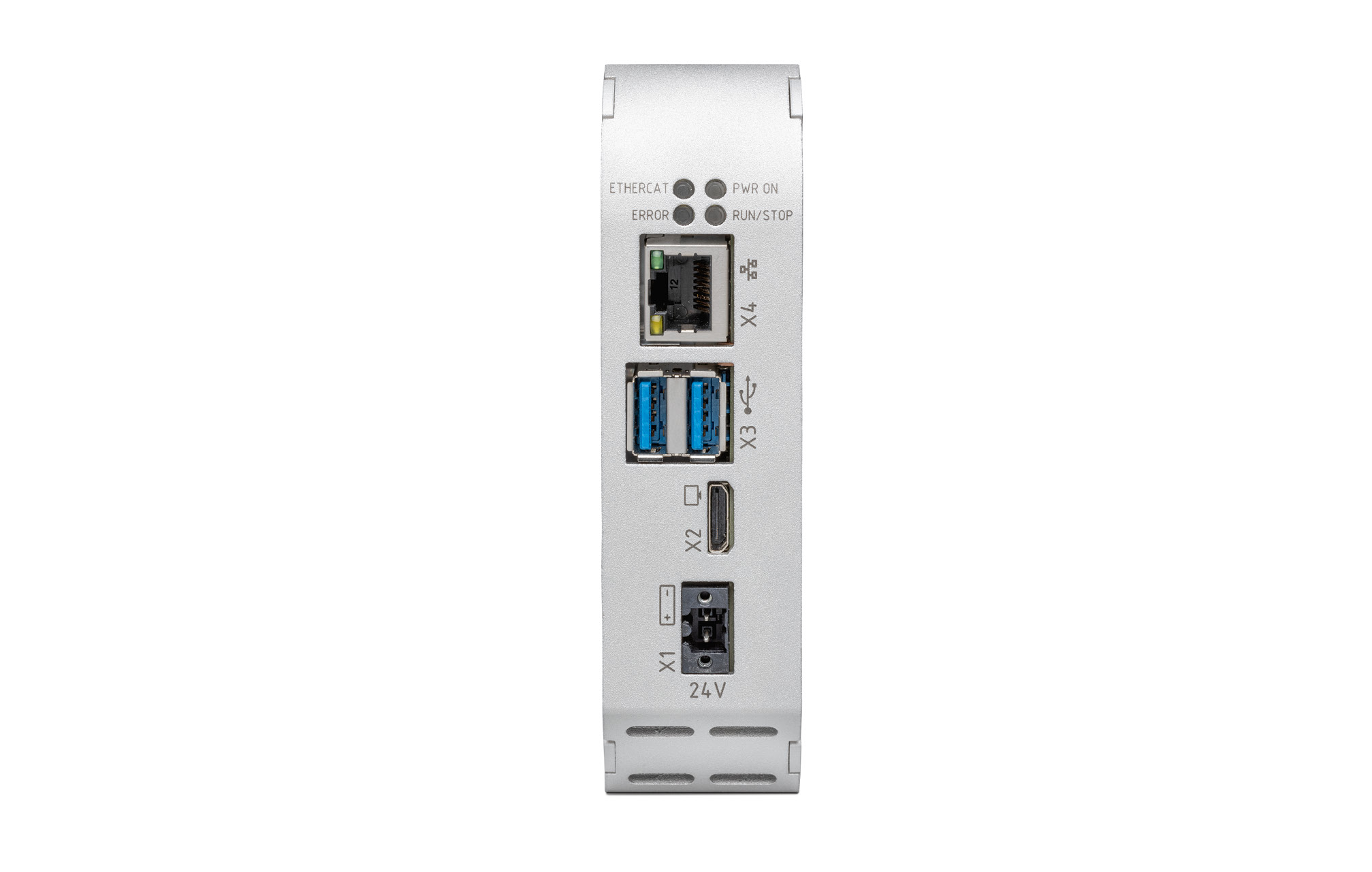
MC-Pi Pro?
Berghof’s MC-Pi Pro impresses with its quad-core CPU and perfectly tuned hardware and software for superior real-time operation. The state-of-the-art Raspberry Pi technology (CM4) and top-notch Berghof engineering ensure top performance in industrial applications.
Even entry-level modules with 2 GB RAM, 8 GB Flash, and 200 kB Retain can be used for a wide range of applications.
Why use FB?
FB is a “reusable component with state” that can be used any number of times with the same logic “made into a component,” and each instance retains its own internal state (memory).
State retention (can have memory)
Timers, counters, latches, and sequence management require a “previous value”; FBs can have their own state in internal variables (functions cannot).
Reusability and consistency
Once made, it can be diverted to any device. Bug fixes and specification changes work for all instances by simply fixing the FB itself -> quality and speed increase.
Multiple placement (instantiation)
Horizontal expansion of the same FB from Motor 1 to Motor 200. Each instance operates independently, avoiding copy-and-paste hell and human error.
Abstraction (Interface)
Complex processing is shown only as “input → output” and the contents are hidden. The upper-level logic can concentrate on “what you want to do,” and the lower-level implementation differences (differences between manufacturers and models) can be absorbed.
Ease of testing
Easy unit testing and simulation, and if I/Os are mocked up, operation can be checked before bringing them to the site.
Maintainability and scalability
Easy to add specifications and expand parameters. Structure does not break even if the project grows.Easy to add specifications and expand parameters. Structure does not break even if the project grows.
How is FB different from FC?
- FUNCTION: Input to output “computation”. Disposable” without internal state.
- FB (FUNCTION BLOCK): An “object” that provides input to output and retains internal state.
Why Use Array?
An array (ARRAY) is a “fixed-length data container in which values of the same type are stored in sequentially numbered “boxes.” They are arranged sequentially in memory and the elements are accessed by index.
Automated horizontal deployment (scale)
When there are many “same type channels” such as sensors/motors/valves, etc., the same logic can be processed at once by array + FOR, avoiding copy-and-paste hell and human error.
Consistency and conservatism
Specification changes only require a single modification to the loop itself, so even if there are many, it is difficult to omit corrections.
Compatibility with I/O and communications
Fieldbus and registers often come in contiguous addresses (WORD arrays) and can be mapped as they are in arrays.
Tabular formatting of recipes/tunings
It is easier to edit each row (channel) from the HMI if thresholds, times, gains, etc. are grouped in an array.
Implementation1
Implementation 1 will explain the steps to actually create a FB by yourself.
Add new FB
Now we will add a Function Block from the OTee Platform.
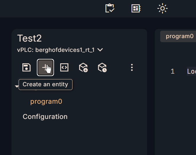
The Add Entity screen will appear.
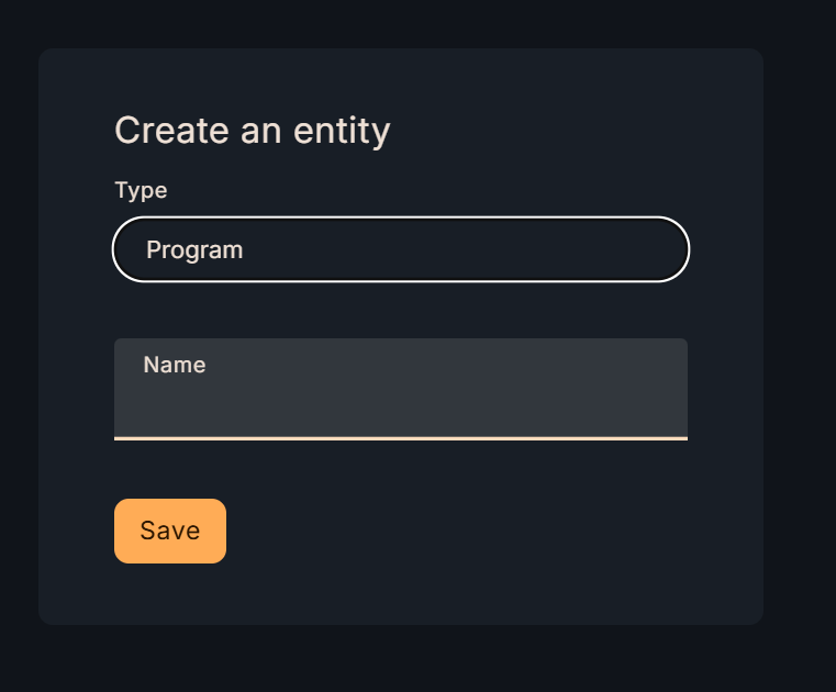
Select Type->Function Block.
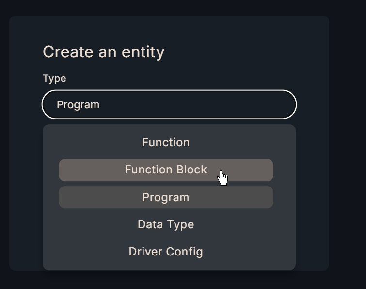
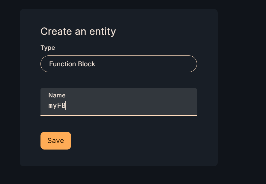
Next, enter the Function Block name in the Name field.
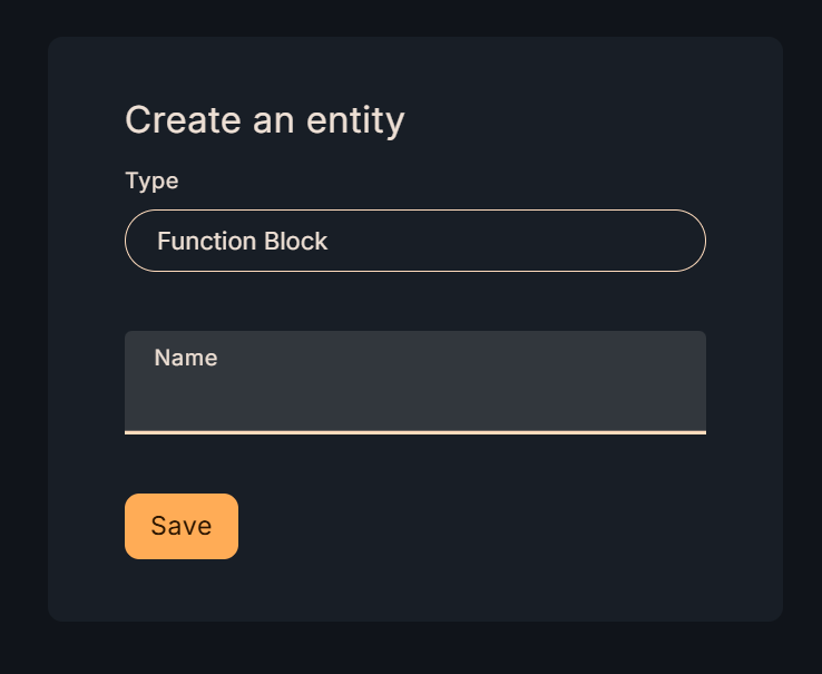
Finally, click the Save button to save the settings.
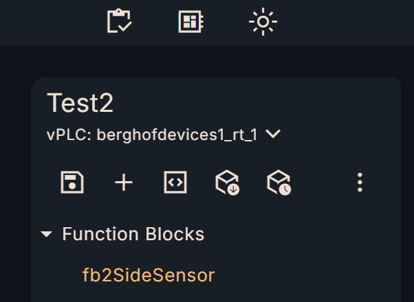
Done!New FB added.
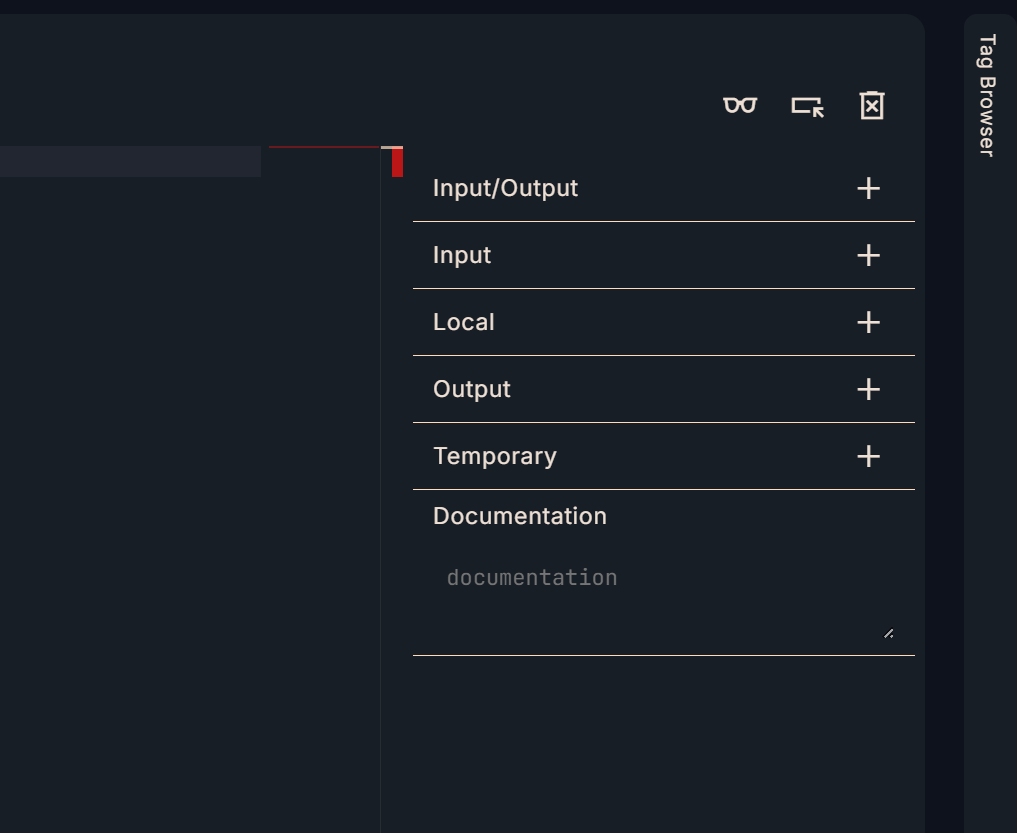
interface
Next, let’s set the input/output parameters in Interface on the right side. In this article, we will use a slightly special parameter called Input/Output.
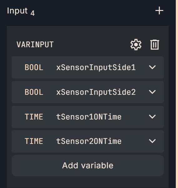
VARINPUT
Here are the input parameters defined in the FB of Implementation 1.
- xSensorInputSide1: Input signal of sensor 1
- xSensorInputSide2: Input signal of sensor 2
- tSensor1ONTime:Sensor 1 signal delay setting, prevents signal oscillation
- tSensor1ONTime: Signal delay setting for sensor 2, prevents signal oscillation
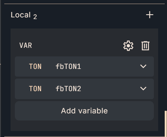
VAR
This is a variable that holds the FB internal memory.
- fbTON1: TON timer for sensor 1 delay
- fbTON1: TON timer for sensor 2 delay
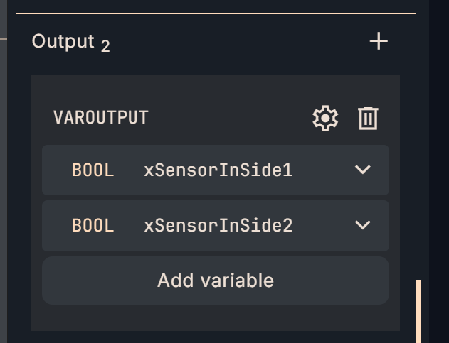
VAROUTPUT
- Here are the output parameters defined in the FB of Implementation1.
- xSensorInSide1: Signal output of sensor 1 (with delay)
- xSensorInSide2: Signal output of sensor 1 (with delay)
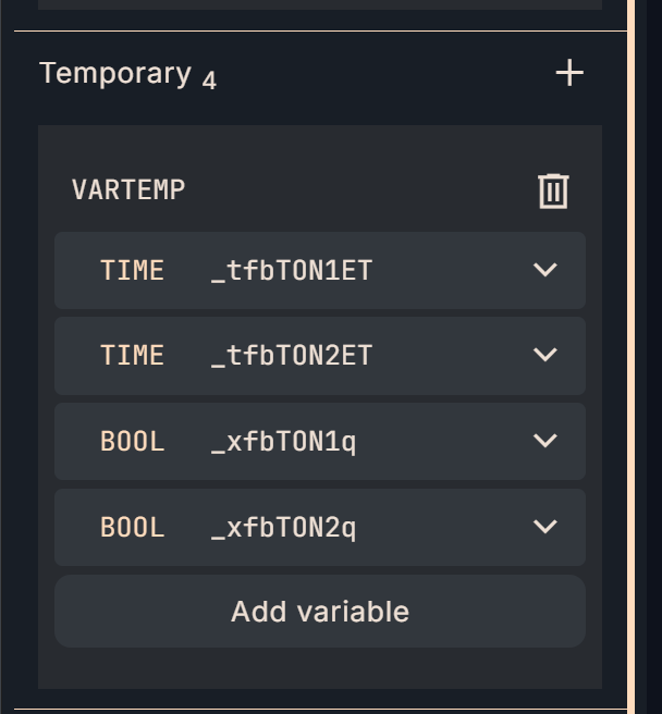
VARTEMP
This is a temporary variable (not retained) inside FB.
- _tfbTON1ET: Delay elapsed time of sensor 1
- _tfbTON2ET: Delayed elapsed time of sensor 2
- _xfbTON1q: Output signal after delay of sensor 1
- _xfbTON2q: Output signal after delay of sensor 2
Program
Here is the FB program for Implementation 1.
(**)
fbTON1(
IN := xSensorInputSide1,
PT := tSensor1ONTime,
Q => _xfbTON1q,
ET => _tfbTON1ET
);
(**)
fbTON2(
IN := xSensorInputSide2,
PT := tSensor2ONTime,
Q => _xfbTON2q,
ET => _tfbTON2ET
);
xSensorInSide1:=_xfbTON1q;
xSensorInSide2:=_xfbTON2q;
MAIN
Next, let’s call the FB we defined earlier in the MAIN program.
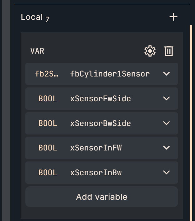
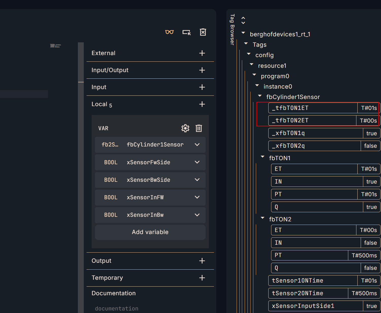
VAR
Define the FB you just added as a data type in Local->VAR->Add variable. This time, define it as “fbCylinder1Sensor”.
Next, call “fbCylinder1Sensor” declared earlier in Editor.
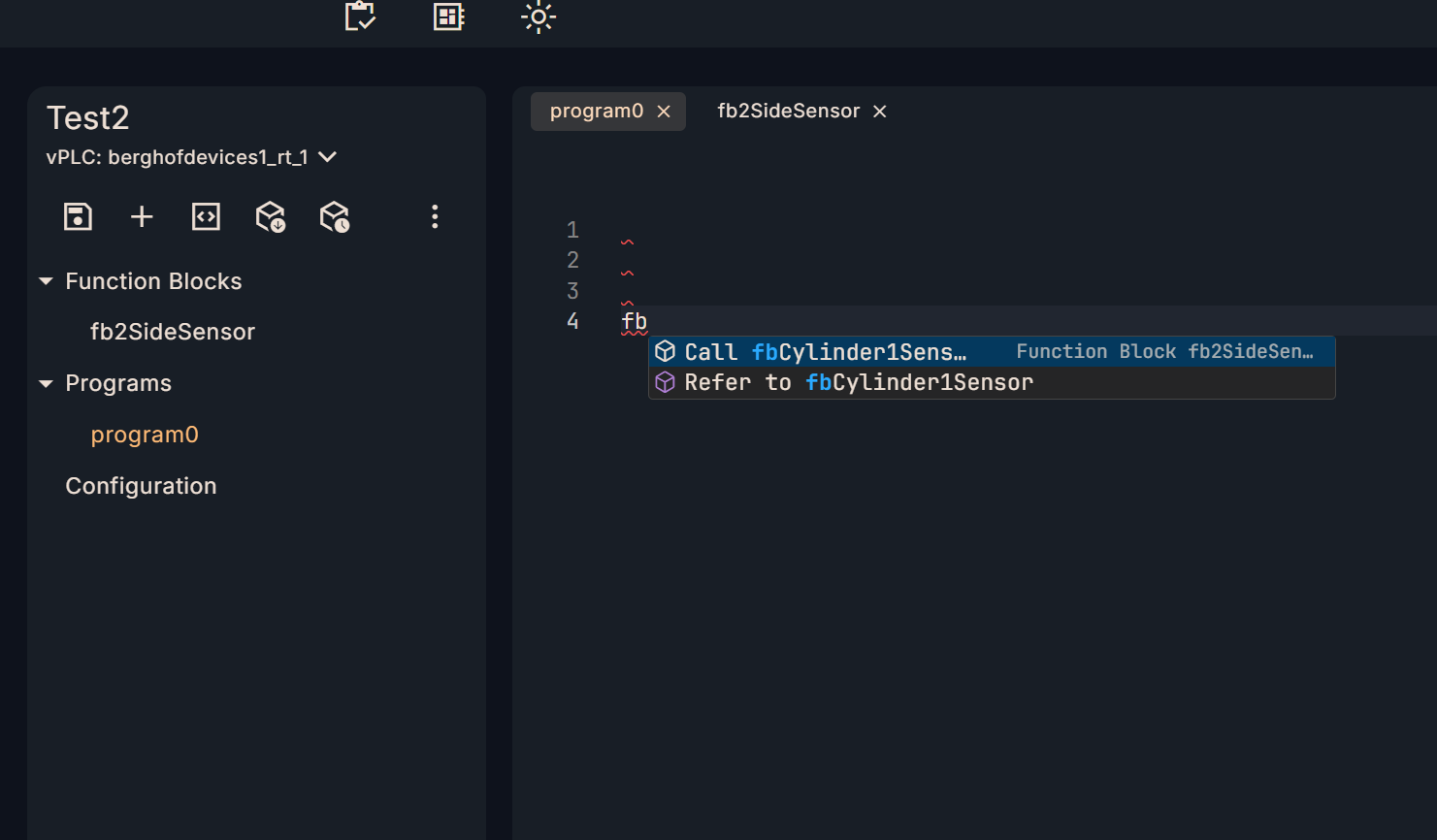
Done!The OTee platform automatically generates all input and output parameters as a Template.
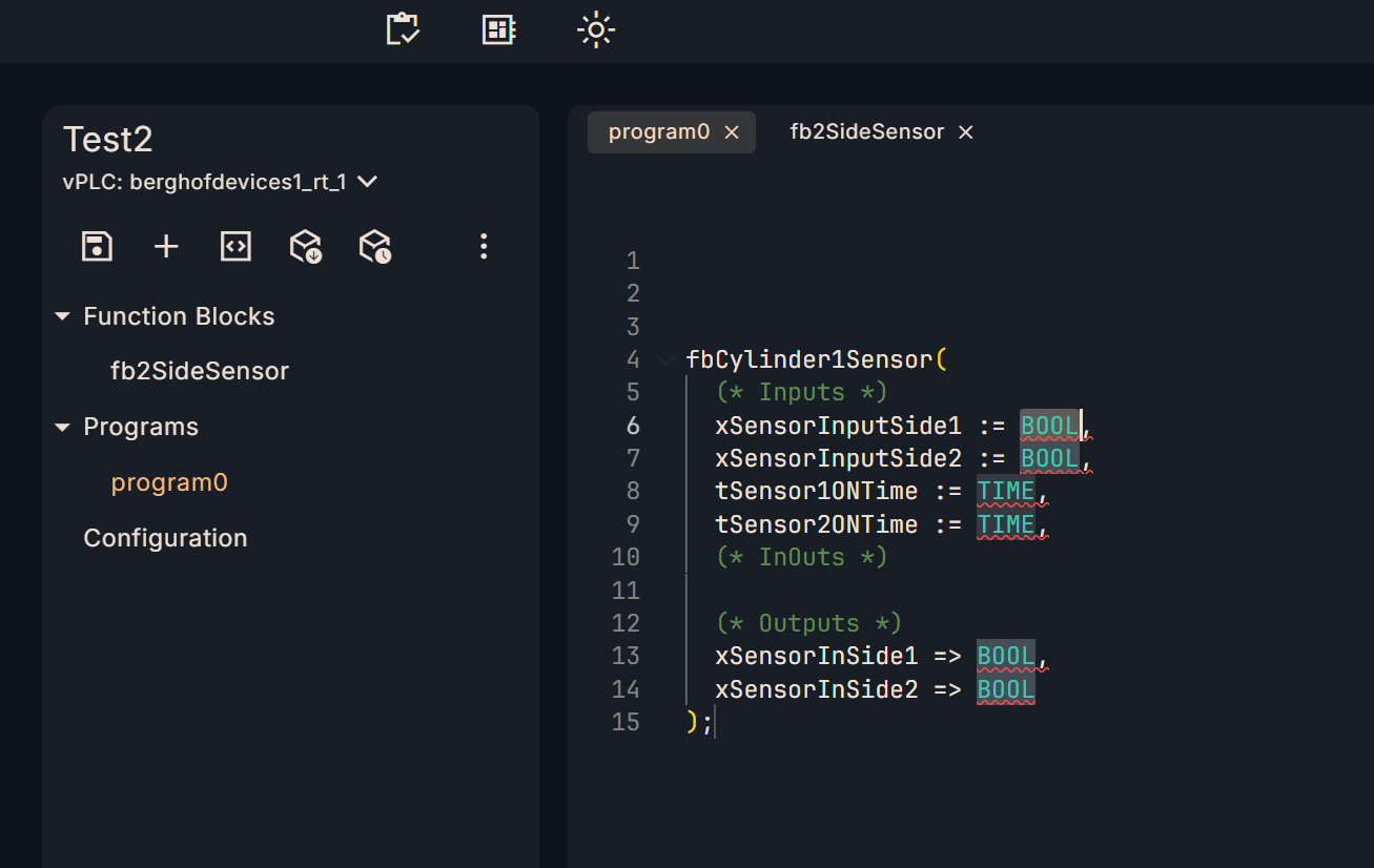
Program
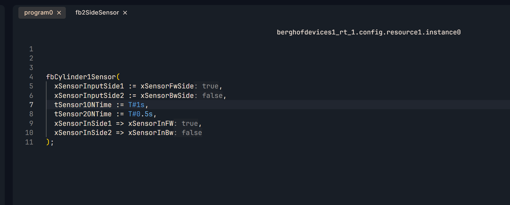
Assign each parameter of “fbCylinder1Sensor” appropriately.
fbCylinder1Sensor(
xSensorInputSide1 := xSensorFwSide,
xSensorInputSide2 := xSensorBwSide,
tSensor1ONTime := T#1s,
tSensor2ONTime := T#0.5s,
xSensorInSide1 => xSensorInFW,
xSensorInSide2 => xSensorInBw
);
result
Done!The FB we created was successfully called from the MAIN program.
The timer inside the FB is also working properly.
Implementation2
Next, create a new FB and call the FB startup created in Implementation 1 -> Extension.
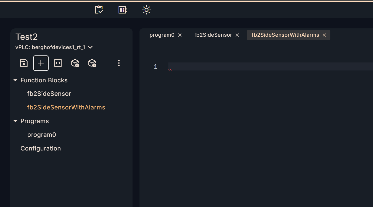
Add new FB
OTee Platform→+ to add a new FB.
Call another FB within FB
Declare the FB created in Implementation 1 above as the new FB.
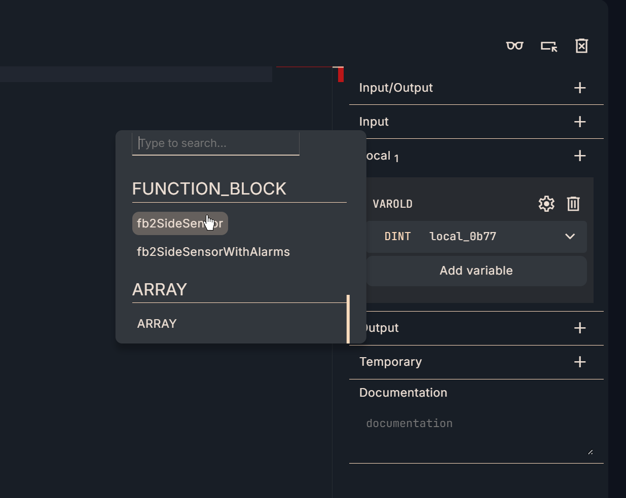
Define array parameters
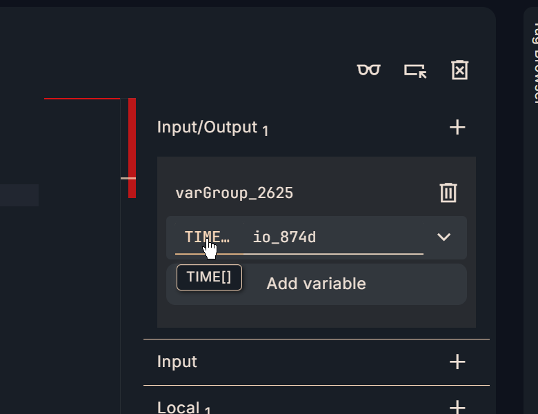
In this Implementation, array parameters are declared in the Input/Output parameters.
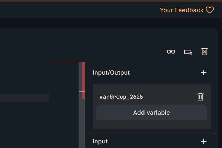
Select ARRAY.
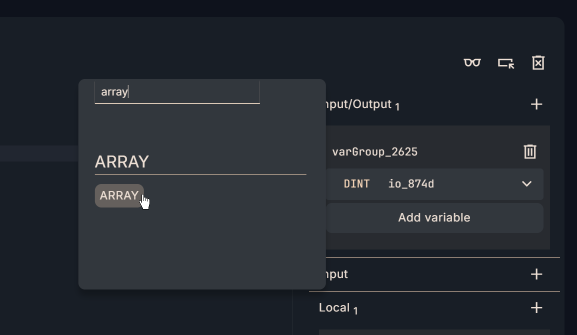
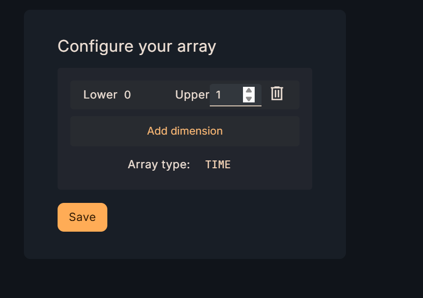
An array setup screen will appear from OTee.
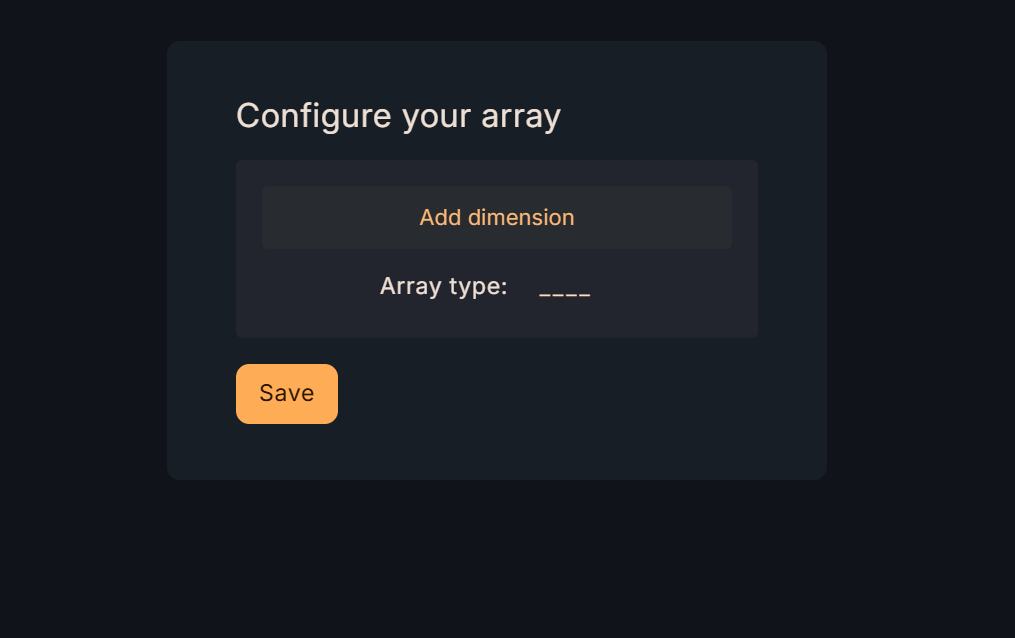
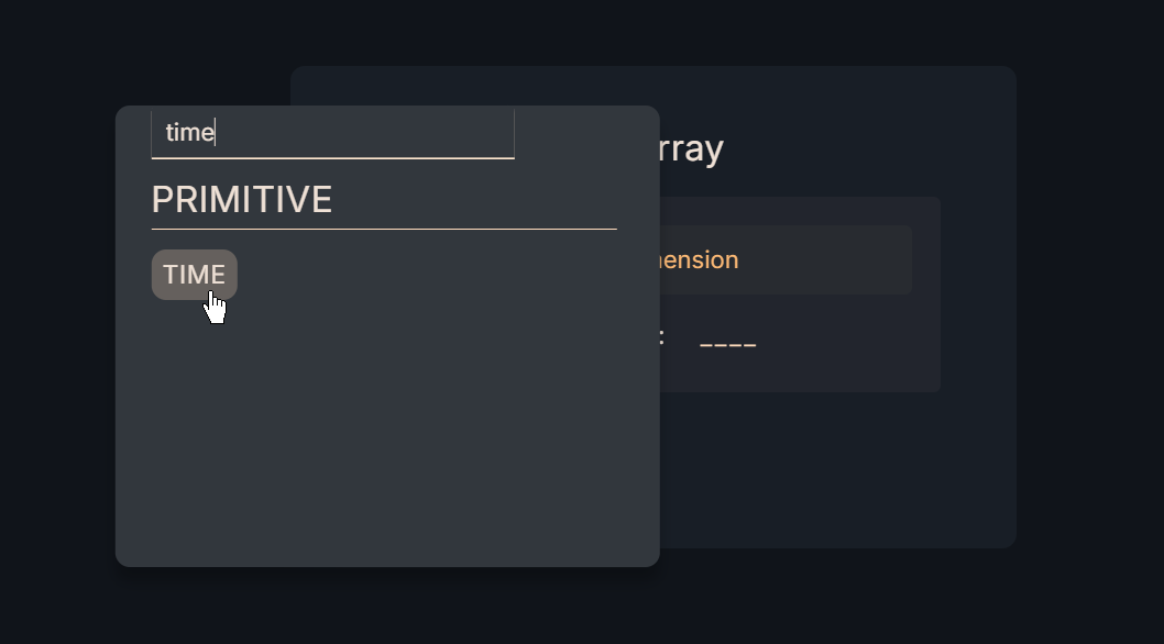
Click Array Type→Set the array data type.
The next step is to define the size of the array with Lower and Upper.
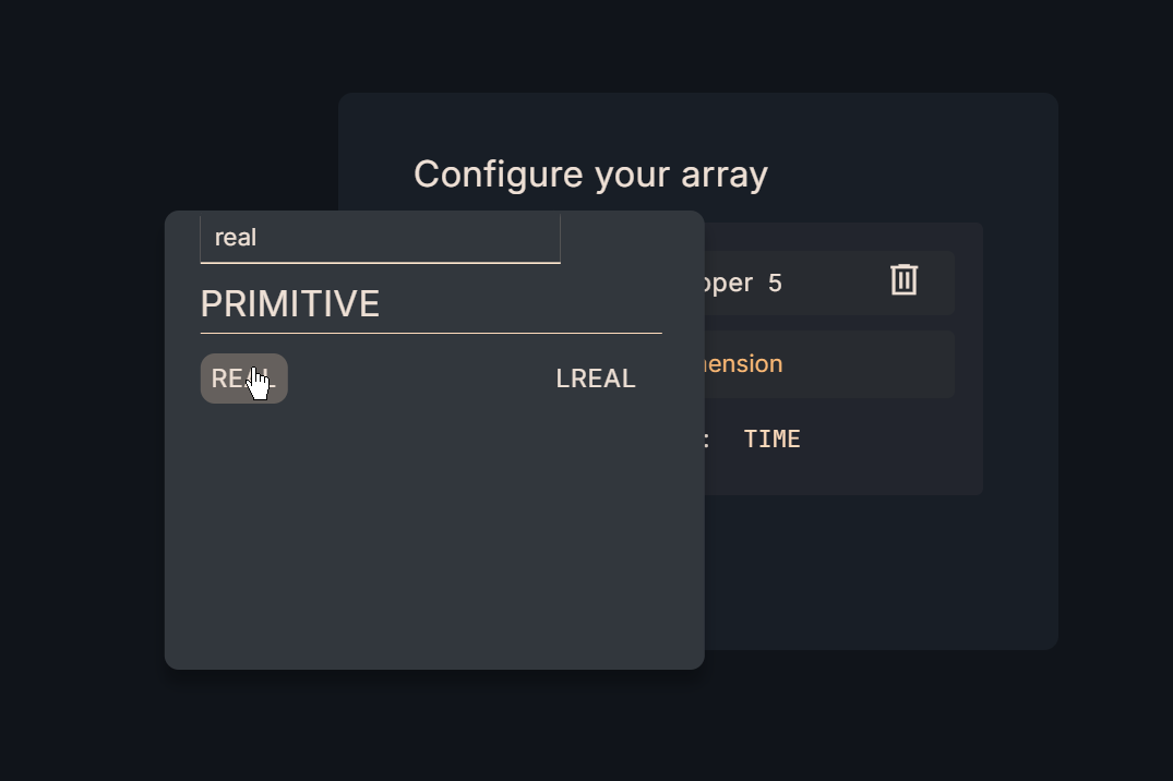
Then, if you want to change the data type of the defined array, right-click on the data type.
Then set the data type to be changed. In this implementation, we will change to a real number type.
Done!The data type of the array variable could be changed to REAL.
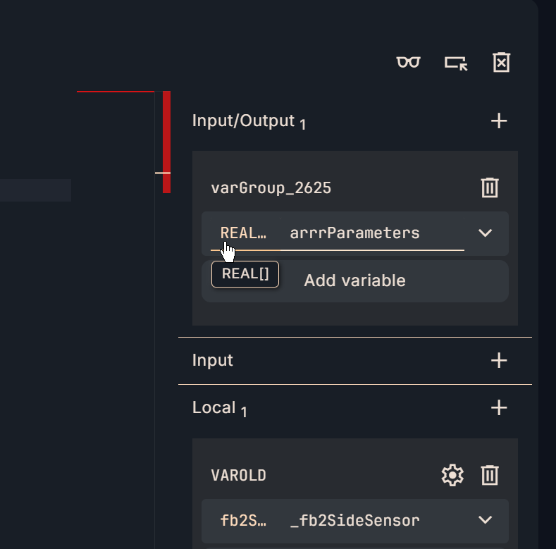
interface
Next, let’s set input/output parameters in Interface on the right side.

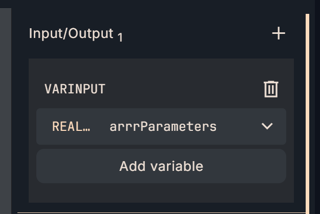
VARINOUT
These are the input/output parameters defined in the FB of Implementation2.
- arrrParameters: Array parameters declared so that FB internal parameters can be set externally.
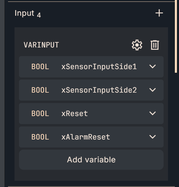
VARINPUT
Here are the input parameters defined in the FB of Implementation2.
- xSensorInputSide1: Input signal of sensor 1
- xSensorInputSide2: Input signal of sensor 2
- xReset:Reset the number of Counters turned on by Sensor1 and Sensor2 to 0
- xAlarmReset: Reset the alarm of FB
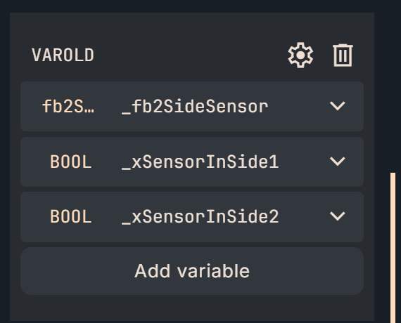
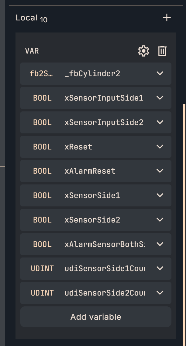
VAR
This is a variable that holds the memory inside the FB.
- _fb2SideSensor:FB defined in Implementation1
- _xSensorInputSide1:Input delay signal of sensor 1 (for FB internal use)
- _xSensorInputSide2: Input delay signal for sensor 2 (for internal use in FB)
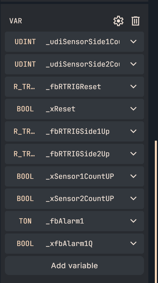
This is another variable that holds the memory inside the FB.
- _udiSensorSide1Counter:Counter of sensor 1 OFF→ON
- _udiSensorSide2Counter: Counter for sensor 1 OFF→ON
- _fbRTRIGReset:Startup detection of Reset signal
- _xReset: Start-up output of reset signal
- _fbRTRIGSide1Up: Start-up detection of sensor 1
- _fbRTRIGSide2Up: Start-up detection of sensor 2
- _xSensor1CountUp: Startup output of sensor 1
- _xSensor2CountUp: Startup output of sensor 2
- _fbAlarm1: Alarm detection timer
- _xfbAlarm1Q: Alarm output
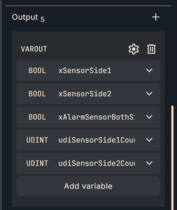
VAROUTPUT
Here are the output parameters defined in the Implementation2 FB.
- xSensorInSide1: Signal output of sensor 1 (delayed, no alarm)
- xSensorInSide2: Signal output of sensor 1 (delayed, no alarm)
- xAlarmSensorBothSideON:Sensor 1 and Sensor 2 simultaneous ON alarm
- udiSensorSide1Counter:Number of sensor 1’s OFF→ON
- udiSensorSide2Counter:Number of sensor 2 turned OFF→ON
Program
Here is the program for Implementation2.
- Clear the two counters to 0 on the rising edge of _xReset (_fbRTRIGReset -> _xReset is TRUE for only one scan).
- Get sensor values with _fb2SideSensor.
- Count up on each rising detection (_fbRTRIGSide1Up/2Up).
- Latch xAlarmSensorBothSideON when both sides ON for a certain period of time (_fbAlarm1 Q).
- Release with xAlarmReset.
- Finally, reflect to output and count for external release.
- *** Translated with www.DeepL.com/Translator (free version) ***
- Here is the program for Implementation2.
- Clear the two counters to 0 on the rising edge of _xReset (_fbRTRIGReset -> _xReset is TRUE for only one scan).
- Get sensor values with _fb2SideSensor.
- Count up on each rising detection (_fbRTRIGSide1Up/2Up).
- Latch xAlarmSensorBothSideON when both sides ON for a certain period of time (_fbAlarm1 Q).
- Release with xAlarmReset.
- Finally, reflect on output and count for external release.
(*Counter Reset*)
_fbRTRIGReset(
CLK := xReset,
Q=>_xReset
);
if _xReset then
_udiSensorSide1Counter:=0;
_udiSensorSide2Counter:=0;
end_if;
(*Sensor Input FB*)
_fb2SideSensor(
xSensorInputSide1 := xSensorInputSide1,
xSensorInputSide2 := xSensorInputSide2,
tSensor1ONTime := REAL_TO_TIME(IN := arrrParameters[0]),
tSensor2ONTime := REAL_TO_TIME(IN := arrrParameters[1]),
xSensorInSide1 => _xSensorInSide1,
xSensorInSide2 => _xSensorInSide2
);
(*Counter UP Operation*)
_fbRTRIGSide1Up(
CLK := _xSensorInSide1,
Q=>_xSensor1CountUP
);
_fbRTRIGSide2Up(
CLK := _xSensorInSide2,
Q=>_xSensor2CountUP
);
if _xSensor1CountUP then
_udiSensorSide1Counter:=_udiSensorSide1Counter+1;
end_if;
if _xSensor2CountUP then
_udiSensorSide2Counter:=_udiSensorSide2Counter+1;
end_if;
(*Alarm Detection*)
_fbAlarm1(
IN := _xSensorInSide1 and xSensorInputSide2,
PT := REAL_TO_TIME(IN := arrrParameters[2]),
Q => _xfbAlarm1Q
);
(*Counter Reset*)
if _xfbAlarm1Q then
xAlarmSensorBothSideON:=True;
end_if;
if xAlarmReset then
xAlarmSensorBothSideON:=False;
end_if;
xSensorSide1:=_xSensorInSide1;
xSensorSide2:=_xSensorInSide2;
udiSensorSide1Counter:=_udiSensorSide1Counter;
udiSensorSide2Counter:=_udiSensorSide2Counter;
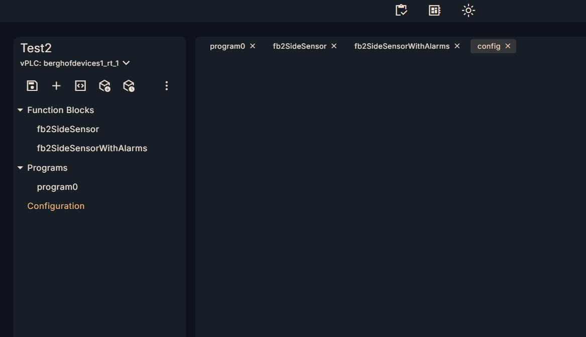
Adding a new Configuration
The last step is to add multiple programs to the project → assign them to new tasks.
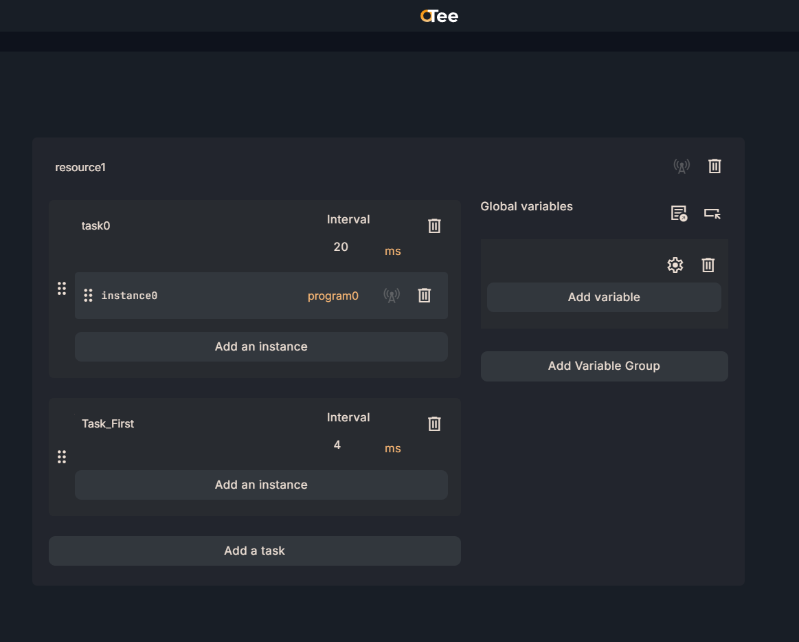
Click on Configuration from the Toolbar on the right.
Add a Task to add a new task.
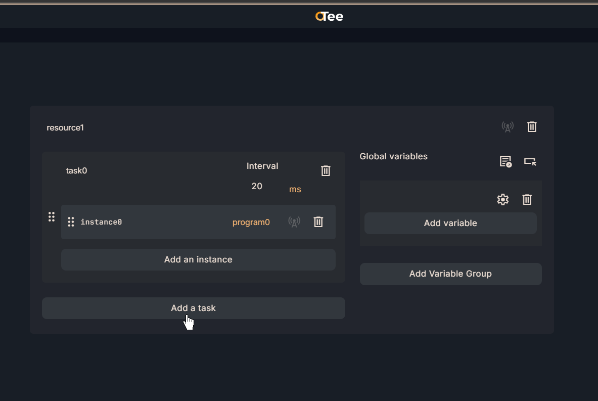
Done!Next, change the Task name.
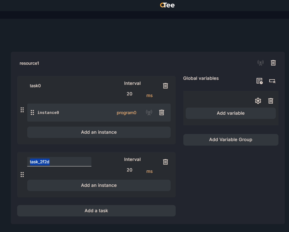
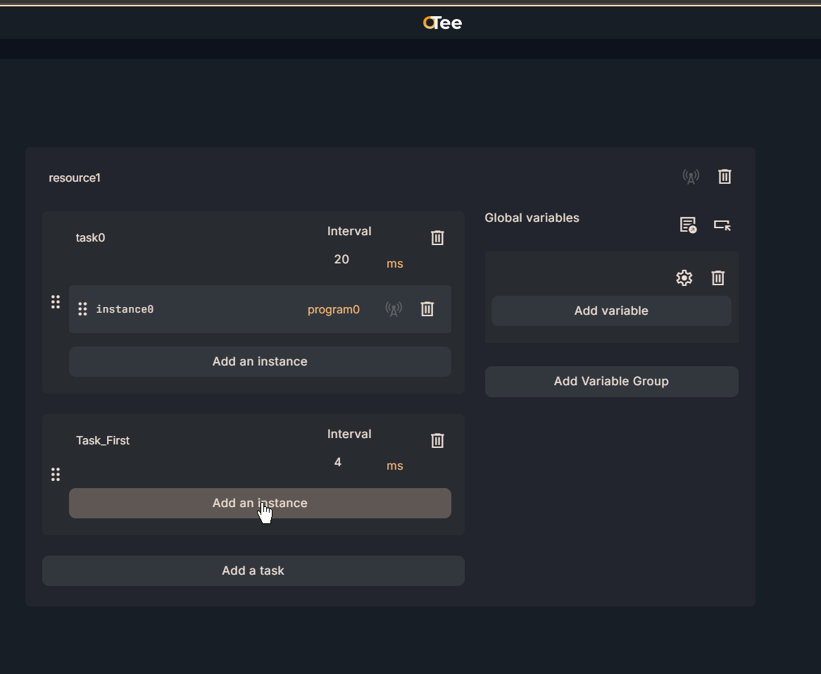
Interval defines the period of the task and is set to 4 ms in this example.
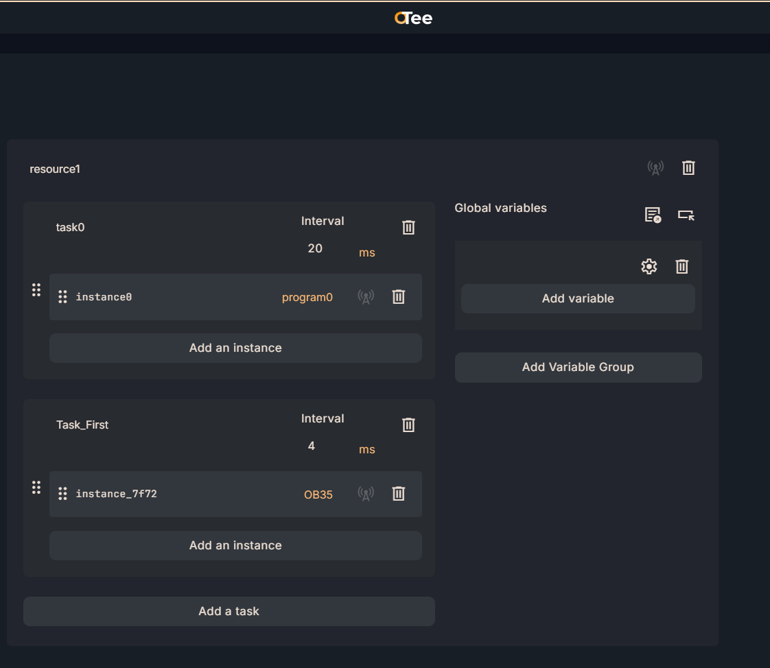
Next, assign the program with Add an instance.
Done!A new Instance has been added.
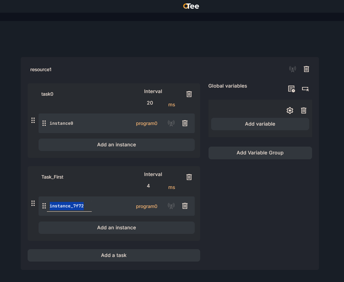
Next, click on the Program column in the figure below.
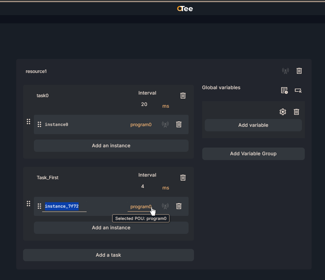
Then set up the program you want to call.
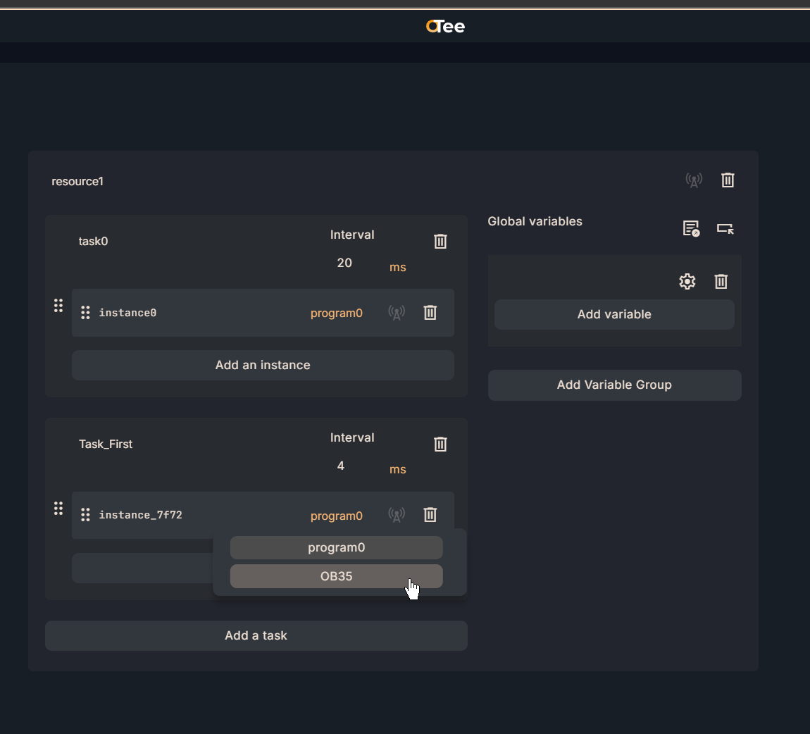
Done!
MAIN Program
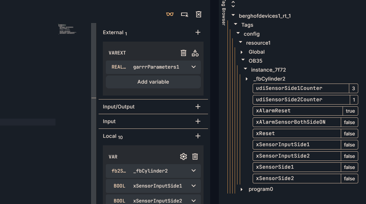
The last program is the MAIN program. Declare the fb2SideSensorAlarms defined earlier as a Local variable.
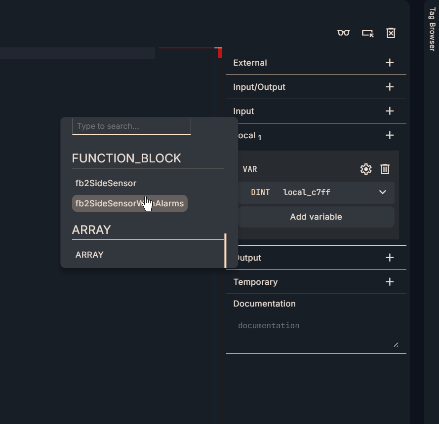
VAR
This is an internal variable defined in Implementation2.
External
Then, in the External column, link to the global variable.
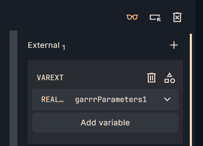
Declare global variables according to your application in Configuration→Global Variables.

Program
This is the MAIN program for this Implementation 2.
(**)
garrrParameters1[0]:=0.1;
garrrParameters1[1]:=0.1;
garrrParameters1[2]:=0.5;
_fbCylinder2(
xSensorInputSide1 := xSensorInputSide1,
xSensorInputSide2 := xSensorInputSide2,
xReset := xReset,
xAlarmReset := xAlarmReset,
arrrParameters := garrrParameters1,
xSensorSide1 => xSensorSide1,
xSensorSide2 => xSensorSide2,
xAlarmSensorBothSideON => xAlarmSensorBothSideON,
udiSensorSide1Counter => udiSensorSide1Counter,
udiSensorSide2Counter => udiSensorSide2Counter
);
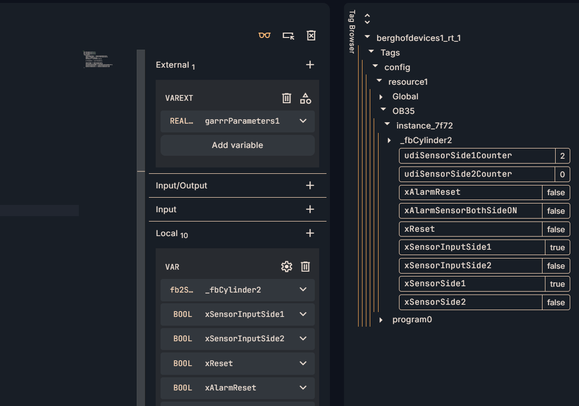
result
Done!The FB we created was successfully called from the MAIN program.
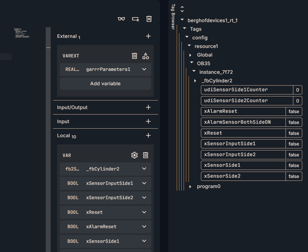
Sensor Counter is added by the sensor input.
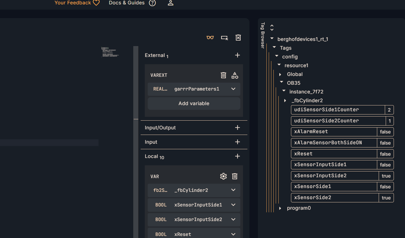
The alarm is then triggered when Sensor Input 1 and Sensor Input 2 are turned on simultaneously.
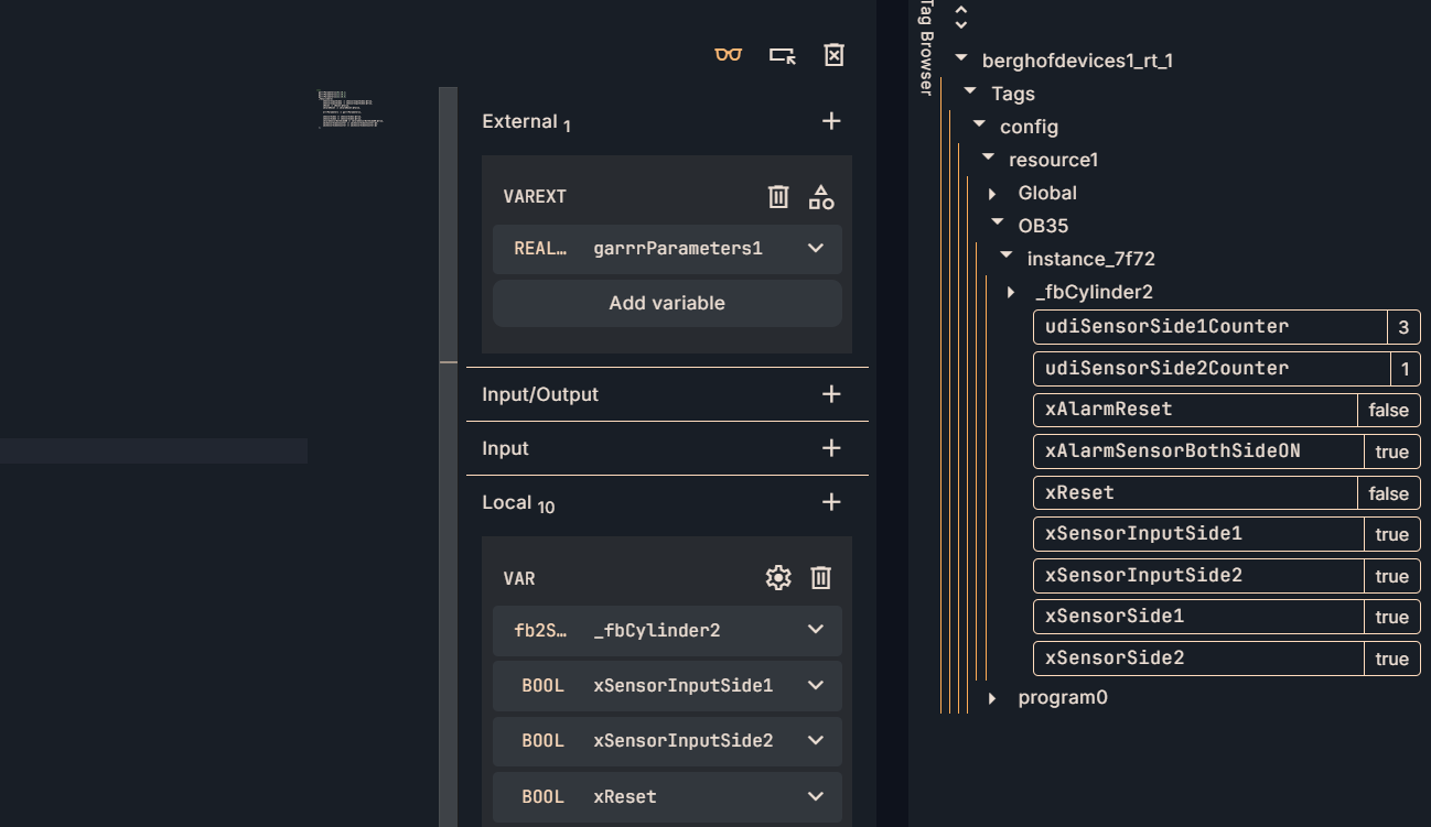
The alarm is also reset when xReset is turned OFF→ON.