Hi, this topic is a basic instruction and wrote some memo in here while i using Mistsubishi FX5U application of RS485 interface control.Why i write this? because in the manual there is not so many details and example about these information;(…
Non-Protocol Communication
Firstly, What is non-protocol communication?
It is a communication method that used to exchange the data between printer,bar code reader..Etc.
For More Information:
Serial Communication by Wiki
system configuration
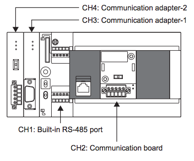
Because the CPU that i am using here is FX5U, only GXWorks3 is available.
*Be honestly, GXWorks3 is not a good item…. ;)!Shut Up!!
Wiring.
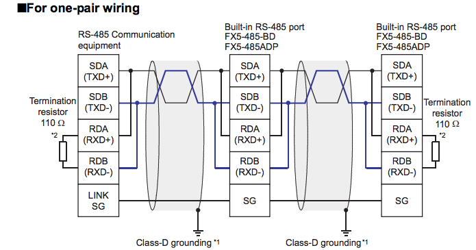
In RS485 there are One-pair wiring and Two pair wiring, and in this application, the devices is only support one-pair wiring.
*the wiring will effect the Termination resistor setting and communication setting inside the GXWorks project, I will explain these stuffs on the below.
Termination resistor
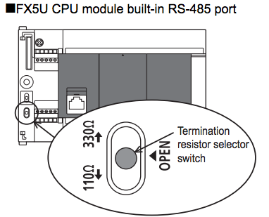
For One-Pair wiring, please push theTermination resistor selector switch to 110 ohm.
For Two-Pair wiring, please push theTermination resistor selector switch to 330 ohm.
Communication Setting in GXWorks3
Navigation Window ->Parameter -> FX5UCPU -> Module Parameter ->485 Serial Port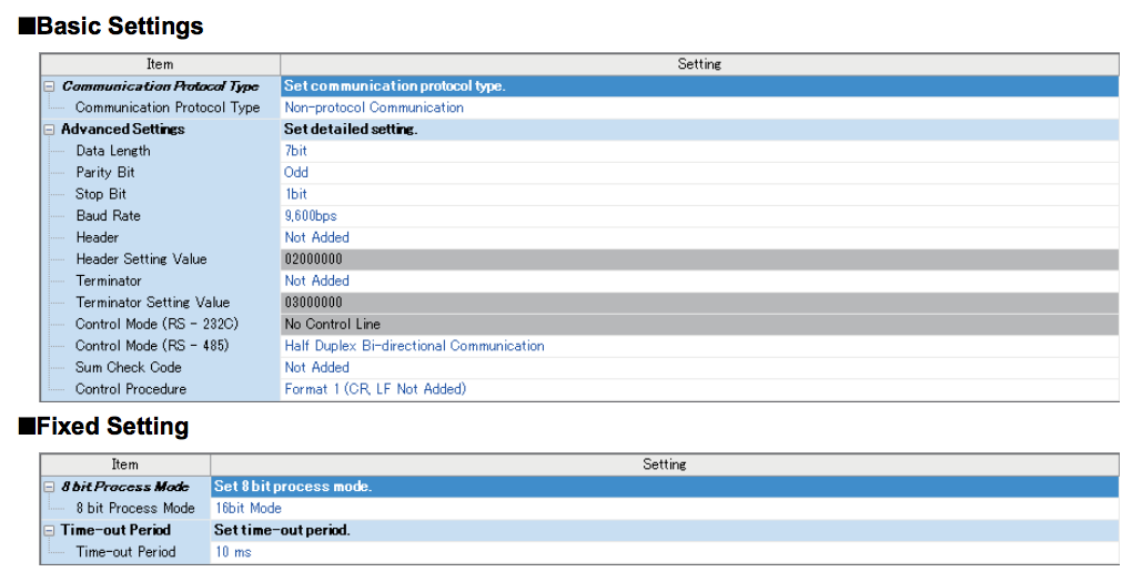
I will not explain so much on what is Data Length,Parity Bit…Something like this, please check inside the Wiki or MR Google ;).
Programming-
OK! Now is the time to explain how to make a PLC program that can use non-protocol communication to exchange the data between other devices.
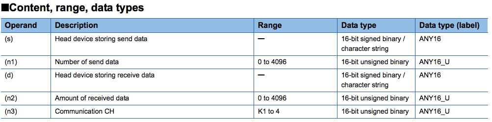
Step1- Check the Instruction
Instruction “RS2” is the main in here.
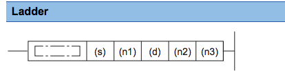
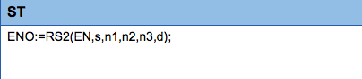
Reference to the Manual:
This instruction sends and receives data in non-protocol communication using the communication board or communication
adapter connected to the CPU module or using the built-in RS-485 port to the CPU module.
I hope that i will have time to write the program in Ladder and ST both 😉 i wish..
Step2:Useful Devices
In the Manual there are so many devices that can get the error code of communications, settings, ABCDEFG.. But in here I will Only show the devices that is the main heart to run the program.
SM8561-
The Flag that using to send the data, you must use a pulse signal to turn it on, and
SM8562:The Flag will auto reset while the sending action is finished.
SM8562-
The Flag that will turn on while all the data is received.It is auto turn on and you must reset it in program.
SD8562-
The System DM that save how many data is received. It is a very useful DM that to make a simple check to make sure all the data that you want is received, then do your own data operation.(move,+-*/,etc..)
Step3:Coding
Now is the time to start programming it!
Here is a basic Example that coding by ST Language with some comment.
[php]
//RS485 non-protocol communication Example
//SM8561 Send Active Flag
//SM8562 Receive Finish Flag
//SD8561 Data Receive Count
//SM8500 Communication ERROR Flag
//While the PLC Sent ‘ID05SET'(ASCII Code) to RS485 Interface devices.
//The Interface will return ‘ID05SETOK’ in the OK Condition.
D400:D:= H35304449;
D402:D:= H544553;
D450:=K7;
D470:=K9;
OUT(SM8500,M0); //Communication Error Flag
If SM8562 then
If SD8561=k9 Then // All Data Received
//Do some data operation With D500;
FMOV(TRUE,D500,K10,D600)//Just move all data to other DM
END_IF;
END_IF;
OUT_T(NOT T2,T2,K2);
SET(T2,SM8561);
RST(SM8562,SM8562);
//Always Exchange Data Between Other Devices.
//DM Start to send from D400
//Send 7 data D400-D404
//Receive 9 data (Byte)
//At Channel 1
//Data Received from devices staring at D500
RS2(TRUE,D400,D450,D470,K1,D500);
[/php]
Thanks and please write the comment if you have any things that would like to discussed;)!
And i will write another one for the RS485-MODBUS communication,CCLink and Ethernet with FX5U.
Bye~~..
Omg, I forgot something..
Here is the link to download the operation manual of FX5U.
Please check it to get more information.
コメント
Hello,
Have you ever used GXWork3 to simulate the ADPWR command for Modbus RTU between 2 FX5U.
Thank you in advance.
Dear,
Sorry for the lately replay and GXWroks3 simulator is not possible to sim the TCP/IP communications.