In this Tutorial I will show you how to Configure the EIP Adapter by using Mitsubishi RJ71EIP91 Modules.

Network Configuration
Here is the configuration in this tutorial. On the Mitsubishi side we have R00CPU with RJ71EIP91, and Connecting to an EIP IO Module Made by Molex(input only)
At the Same time, Rockwell PLC is the exclusive owner in this network.
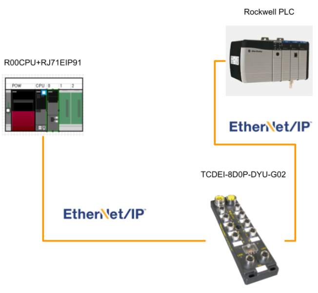
Adapter Side
You can use other Ethernet/IP Adapter devices but not just Molex.
(Codesys/Raspberry/Beckhoff..etc)
Here is a tutorial to configure your codesys runtime as a Ethernet/IP Adapter.
Configuration Tools
A Configuration tool is used to configure the network setting of RJ71EIP91.The tool name is “EtherNet/IP Configuration Tool for RJ71EIP91”
Download
Please access the following link to download the tools:

Please register as a member.

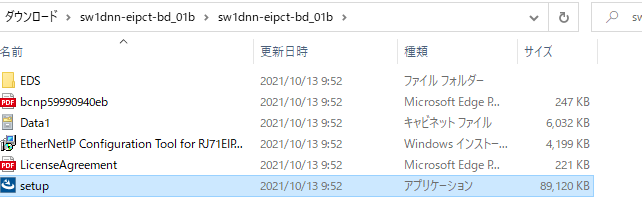
A Zip file is downloaded.

Installation
Now we can install this configuration tool.
Unzip the zip and double click the setup exe.
Your OS will restart.

Next>.

Choose English.

Setup your installation path and Next>.

Install.

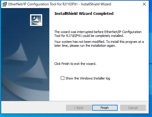
Please wait a minute..

Finished.
Create your project
Now I will show you how to create the project in GXWorks3 step by step.
Hardware Configuration
Project>New to create a new project.

R00CPU is used in my case.

insert the Power supply,Rack in the Module Configuration, and also RJ71EIP91.

compile your project to check for any errors or not.

Download if there is no error in your project.

Let’s go to Diagnostic>System Monitor to check the CPU status first.

Good,No Error.

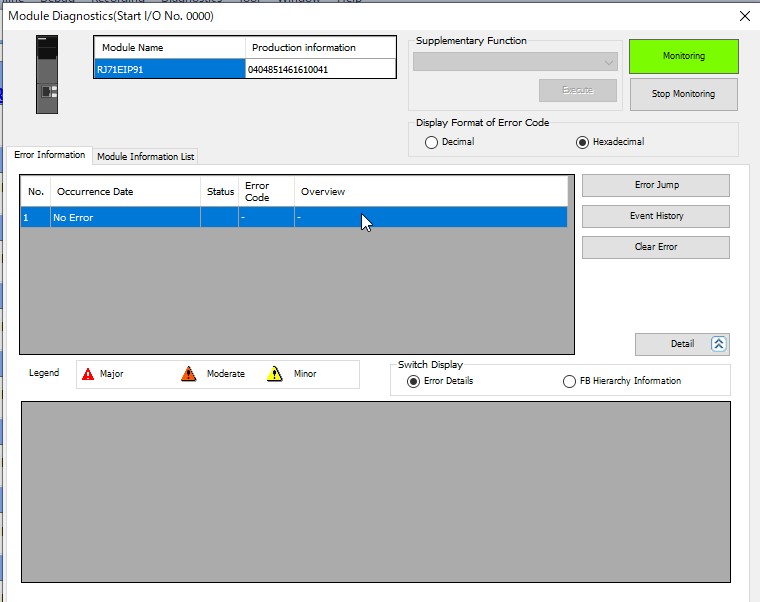
Click the Module RJ71EIP91.
Module RJ71EIP91 is working normally.
Parameters
After the Module is inserted, we need to set the parameters.
Only IP addresses can be configured inside GXWorks3.
Parameter>Module Information>0000:RJ71EIP91.

Click the IP Field.

In this tutorial IP 192.168.1/47/24 is configured.
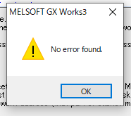
Press the Check button to check any errors.

No error found.Good.
Download the parameter to your CPU.

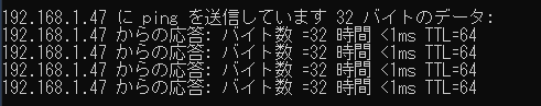
Reset your CPU, and Ping to your EIP Module.
Ping can not succeed if you do not reset the CPU.(Do not ask me why.)
Configuration Tools
Now we can start the EIP Configuration Tools to set up the network.
Go to the installation path of your tool and start EIPCT_Console.

This is the version that I installed on my pc.

A popup of Add New Element is shown.Please enter the IP that you configured before in the Module.

This is the screen of the Configuration Tool.

Add EDS
EDS File is a device description file of the EIP Devices.
Go to Library>Add to add it into your library.

次へ(N).

Press the Browse button to find your EDS File.

Select the EDS File that you need to insert.

次へ(N).

緑のMarkがついたら、インストール成功です!
次へ>をクリックします。

Finished!

Insert Device
This time we will use RJ71EIP91 as an IP Scanner and Adapter need to be configured here.
Device Library>EtherNet/IP Devices>Manufacturer name>Communications Adapter>Choose your module.

Select the device that you will use, and right click>Insert in Configuration.

The following popup is shown.
This is the screen to let you configure the device name, connection parameters,etc..
Go to the Connection Tab and press Add.

Choose Input Only.

Then delete the Exclusive Owner, Choose Exclusive Owner> Remove.

Finished.

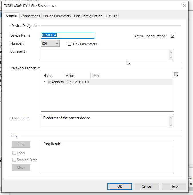
Next Step is to configure the IP address of your Adapter.

At this time,the IP is 192.168.1.101.

Configuration Download
Finally we need to download the configuration to the module.
File>Go Online.

The status is changed to Online.

File>Download.

Pop Up is shwn.
Check the .apa Checkbox and download it.

Done!

You can also use the ping button to test the connection.

Module IO Setup
It is not a must step, but I always configure the IO data as Structure Data Type.
Let’s Check the IO of RJ71EIP91.
Right Click the Module>Open System Parameter.

Select the I/O Assignment Setting> Start XY from 0000, 32 points are used.

Structured Data Types−Input
Go to Label>Global Label>Structured Data Types>AddNew Data.

Enter your Structured Data Types.

Define these variables.

Structured Data Types−Output
Go to Label>Global Label>Structured Data Types>AddNew Data.
Please reference the Manual to create the output variables.

Define in Global Label
Define these 2 devices in the Global Label.

Register the Library
There are so many methods to access the buffer memory,FROM/TO is the most common way but I do not like it.Reference to the Manual, Function Block for Class1 communication is provided by Mitsubishi and it will be used in this tutorial.
Go to Project>Library Operation>Register to Library>Add.

Insert the Module Label
Module Label>Choose 0000:RJ71EIP91>Add Module Label.

A Global Label for that device is added.

Insert the Module FB
Adding the Function Block is the same way.
Go to Module FB>Select the Drop list from Display Target>Choose RJ71EIP91.

Choose both FB of Write and Read , Right Click to Add to your Project.

FB is also inserted in your Project.

Compile the Project and make sure no errors exist.

Implementation
After we finish all the configuration of your Modules, now we can start to make the program.
Input Mapping
This is the Ethernet/IP Input Modules from Molex, and Let’s check the mapping of this device first.
Referenced by the Manual, 8Bytes of input is received from it.We only need the input signal, so Offset 0x02 is our target.

M+RJ71EIP91_Class1GetInputData
This is the function block that I used here and it provided a class Communication to read the input data.The Communication will start while i_bEN=True..


Input Parameters
| i_bEN | Bit | True=Start to Communicate |
| i_stModule | Structure | The Module Label |
| i_uConnectionNo | Word | The Connection Number |
Output Parameters
| o_bENO | Bit | True=Block is running |
| o_bOK | Bit | True=No Error |
| o_bErr | Bit | True=Error |
| o_uErrId | WORD | Error ID |
| o_uStatusId | WORD | StatusID |
| o_uInputData | WORD | your Input Data’s Device offset |
Error Code

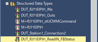
DUT_RJ71EIP91_ReadIN_FBStatus
Now we can define the Structure Data type for the Function Block status.

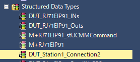
DUT_Station_Connection2
And then the Structure data type of Adapter.

MAIN
Local Label
Add the Local Label for the instance of Function Block and Devices.


Insert FC
I will create a Function to map the data, the output is counted from Z0, starting at D0.


| Z0:=zBase+1; FC_GetStation1PortData.bP1A:=D0Z0.0; FC_GetStation1PortData.bP1B:=D0Z0.1; FC_GetStation1PortData.bP2A:=D0Z0.2; FC_GetStation1PortData.bP2B:=D0Z0.3; FC_GetStation1PortData.bP3A:=D0Z0.4; FC_GetStation1PortData.bP3B:=D0Z0.5; FC_GetStation1PortData.bP4A:=D0Z0.6; FC_GetStation1PortData.bP4B:=D0Z0.7; FC_GetStation1PortData.bP5A:=D0Z0.8; FC_GetStation1PortData.bP5B:=D0Z0.9; FC_GetStation1PortData.bP6A:=D0Z0.A; FC_GetStation1PortData.bP6B:=D0Z0.B; FC_GetStation1PortData.bP7A:=D0Z0.C; FC_GetStation1PortData.bP7B:=D0Z0.D; FC_GetStation1PortData.bP8A:=D0Z0.E; FC_GetStation1PortData.bP8B:=D0Z0.F; ; |
Program
| Y10:=True; IF EIPModule1_IN.b00_ModuleReady AND EIPModule1_IN.b1F_CommReady AND NOT bStop2Comm THEN bStart2Comm:=TRUE; ELSE bStart2Comm:=FALSE; END_IF; fb_RJ71EIP91_GetInputData( i_bEN:=bStart2Comm ,i_stModule:=EIP91_1 ,i_uConnectionNo:=2 ,o_bENO=>st_fb_RJ71EIP91_GetInputData.o_bENO ,o_bOK=>st_fb_RJ71EIP91_GetInputData.o_bOK ,o_bErr=>st_fb_RJ71EIP91_GetInputData.o_bErr ,o_uErrid=>st_fb_RJ71EIP91_GetInputData.o_uErrid ,o_uStatusId=>st_fb_RJ71EIP91_GetInputData.o_uStatusId ,o_uInputData=>D10 ); ; fb_R_Trig1(CLK:=st_fb_RJ71EIP91_GetInputData.o_bErr); IF fb_R_Trig1.Q THEN bStop2Comm:=TRUE; END_IF; IF bReset THEN bStop2Comm:=FALSE; END_IF; Station1_PortData:= FC_GetStation1PortData(10); |
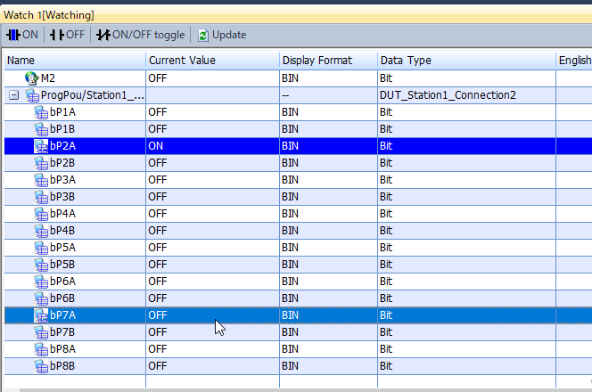
Result
The Function block is executed without Error.

And the data from Adapter is Transferred to the device.