This is the third episode of the Tutorial series on DELTA Motion Control’s RM200 Lite – CPU20L. This time, we will explain simple User Program creation, IO output, etc.
Let’s get started!

Using Command Tools
Select Command
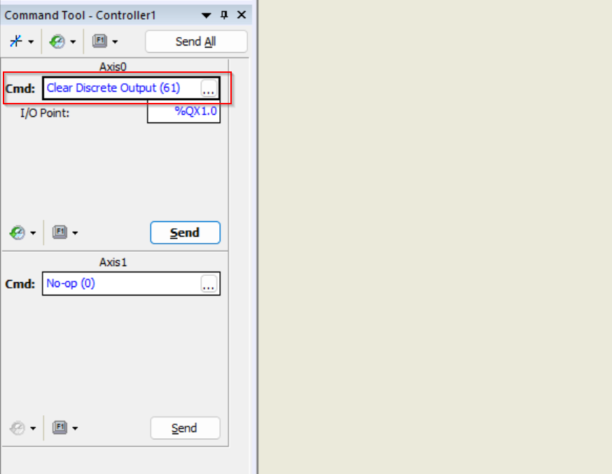
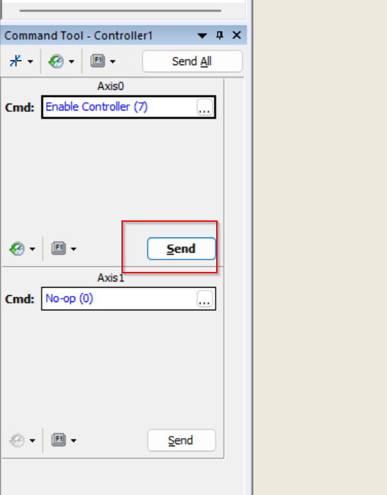
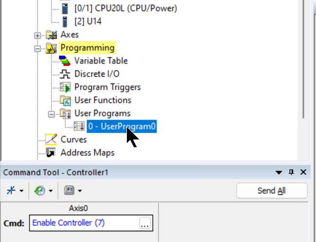
To the left of RMCTools is the Command Tool, which allows you to issue commands directly to each axis.Axis0 is the CPU itself, click on the … button next to Cmd.
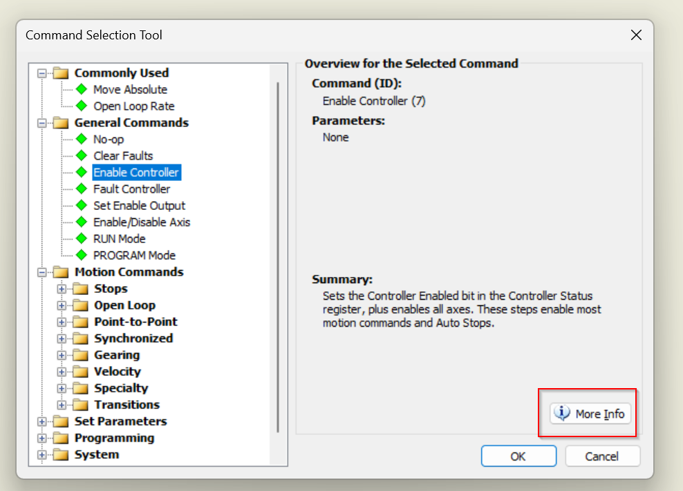
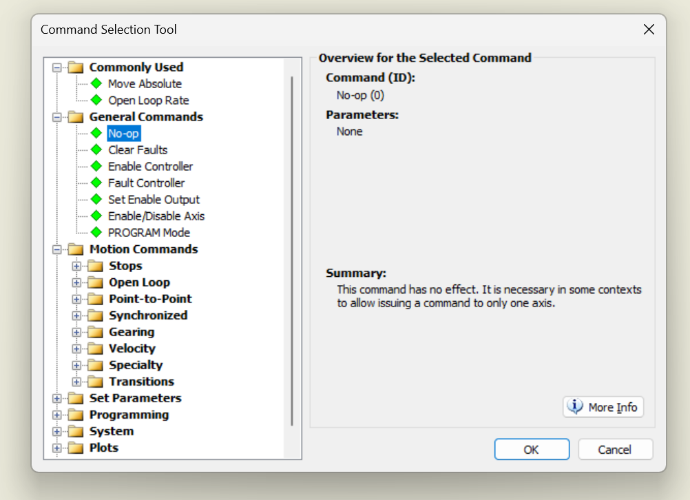
The Command selection screen is now displayed.
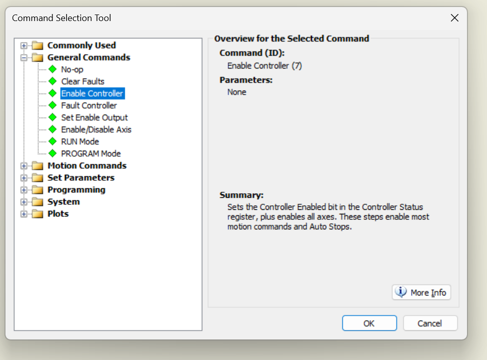
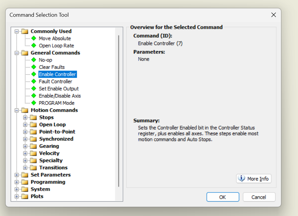
Select the command you wish to execute on the appropriate axis and press >Ok to proceed. In this example, select Enable Controller and press >Ok.
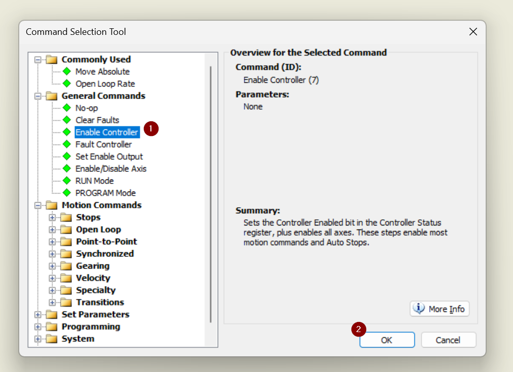
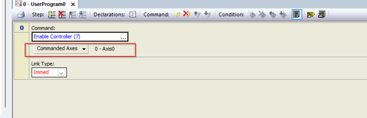
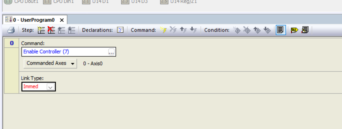
The operation is as shown in the figure below.
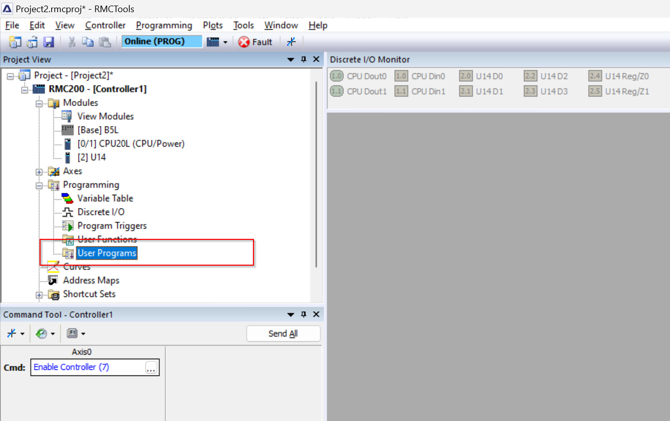
Now that the Cmd is set to “Enable Controller(7)”, let’s issue a command to Axis0 using the Send button.
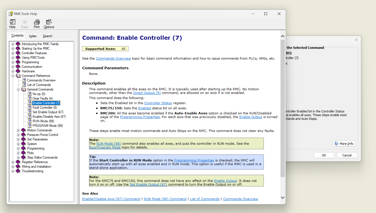
More Info
If you have any questions about the command you want to execute, click on More Info.
Each command has a detailed description.
Directly Input
You can select a command directly without having to select the command from the … button every other time.
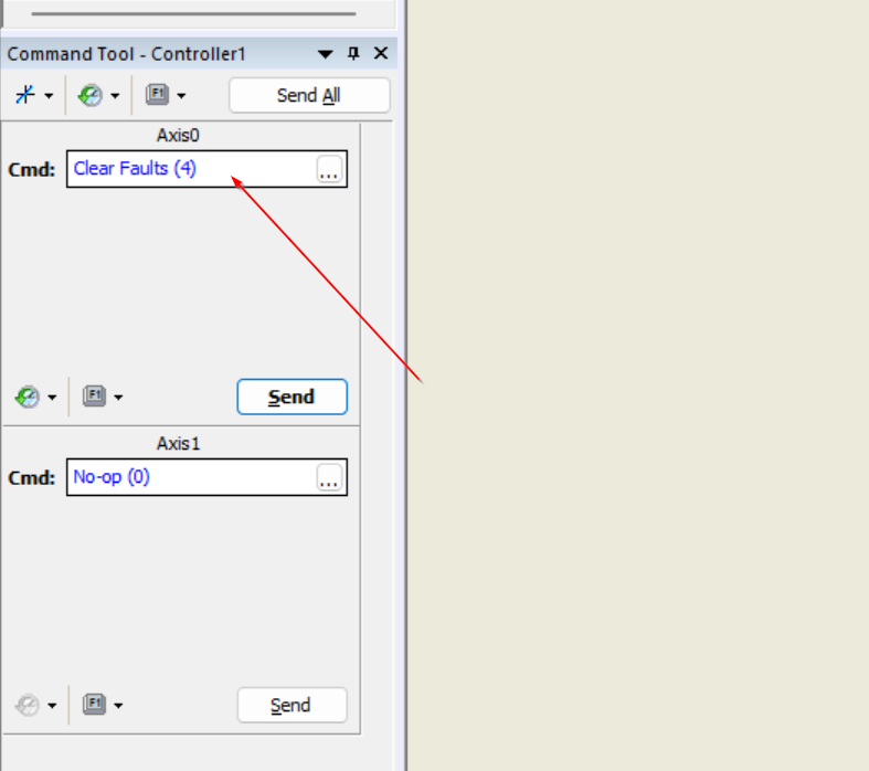
The operation is as shown in the figure below.
User Program
In the third part of the Tutorial, we will discuss the creation of User Programs, a folder in the Programming folder called User Programs, which can be used to execute complex command sequences on the RMC without interfacing with PLCs or other controllers. User programs can execute complex command sequences on the RMC without interfacing with the PLC or other controllers.
This allows the RMC to respond to events within the control loop time independent of the PLC Scan. It also reduces PLC programming required.
The number of User Programs is limited only by the memory capacity of the RMC.
Note that the RMC CPU is only in Run Mode for User Program execution.
Add New Program
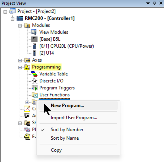
To add a new User Program, click Program>User Programs>right click>New Program.
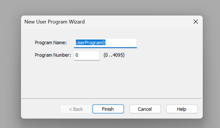
Enter Program Name and Program Number.
Done!User Program has been added.
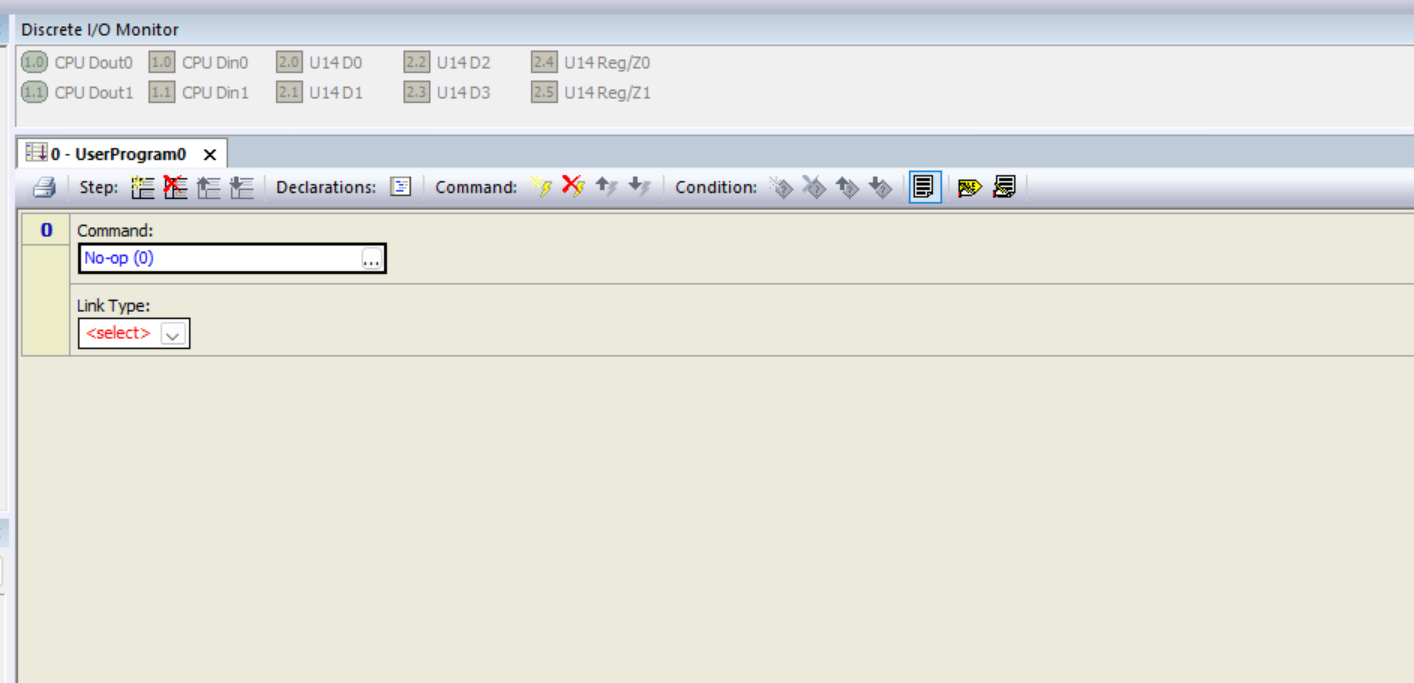
Double-clicking on User program will bring up the program Editor. A user program consists of several steps, each of which can execute several commands for one or more axes. The series of steps are linked in a sequence, and each step takes one loop time to execute.
Loop Time?
The RMC is a Process that reads inputs, computes a control algorithm, and updates outputs at specific intervals. This interval is also called Controller loop time, as the controller repeatedly Loops the code.
RMC always runs with a loop time setting, and when all calculations for one loop are completed, it waits until the next loop time before performing the calculation again.
Program1
Step0
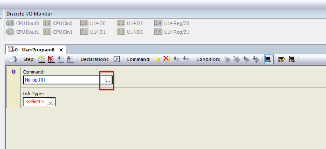
First click on the … button to modify the Step0 ExecutionCommand.
The Command selection screen appears.
In Step 1, we want to enable the Controller, so select General Commands>Enable Controller>Ok.
Done!Now Step0 is to execute Enable Controller(7), and after specifying Command、 you will see an item called Command Axes.Each command in a step can be issued for one or more axes simultaneously, and is a configuration item that defines the axis to which the command is issued. In the example below, it is to issue the Enable Controller (7) command to Axes0.
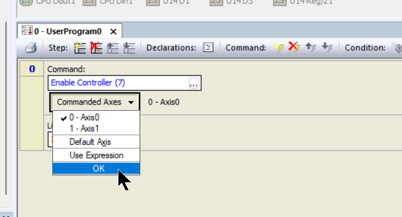
If you want to add Command Axes, click directly on Command Axes and the drop-list will appear.
Done!
Step1
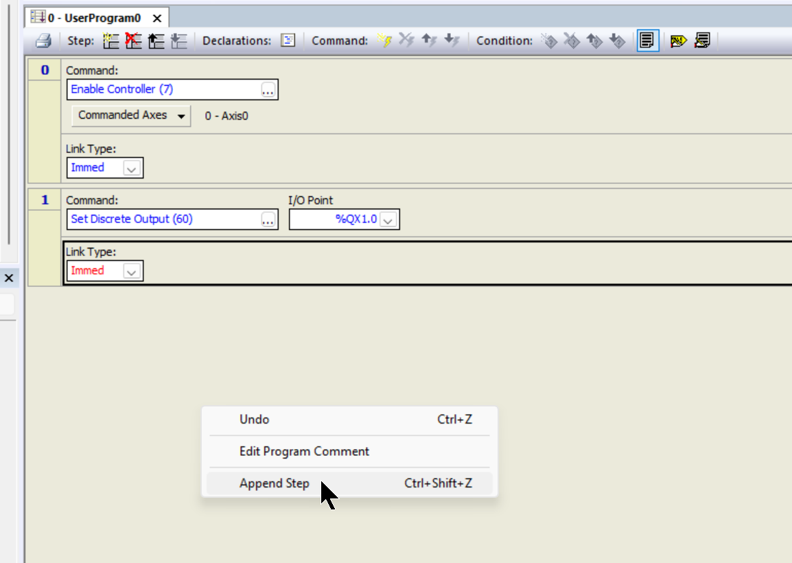
To add a new step, right-click on an empty space in the Program Editor>Append Step.
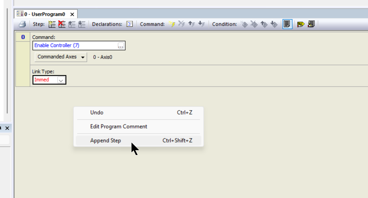
Done!New steps have been added.
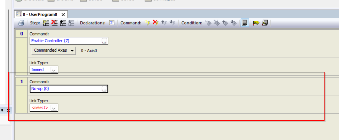
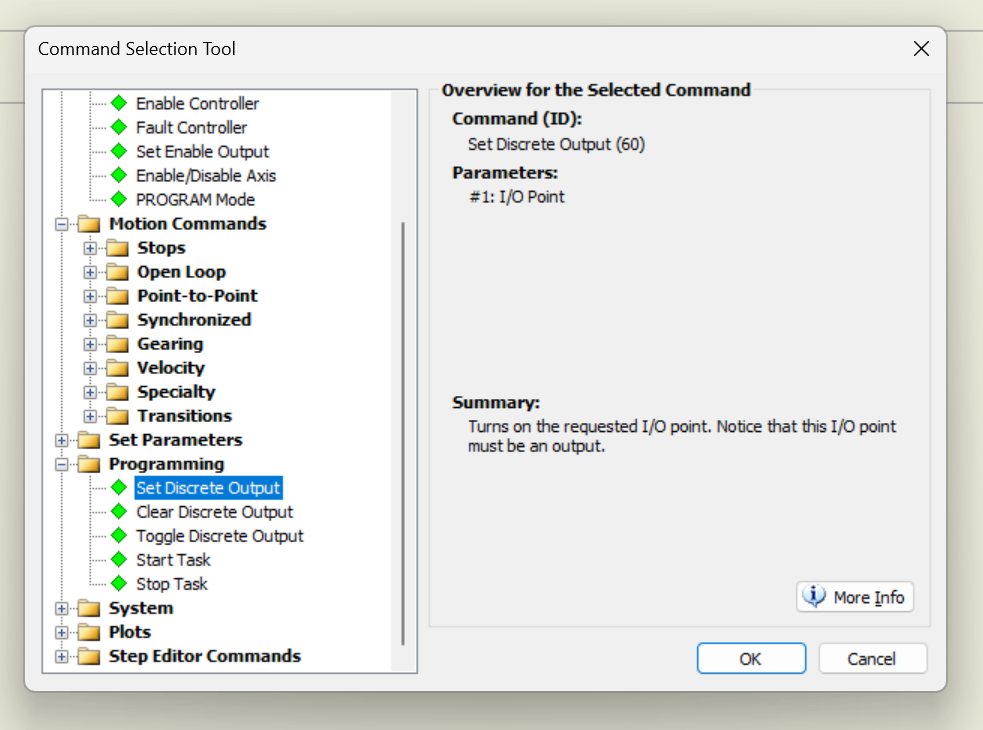
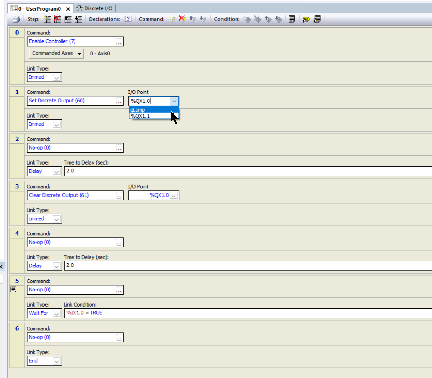
In Step 1, we want to output Discrete Output %QX1.0 True, so select Programming>Set Discrete Output>Ok.
Done!
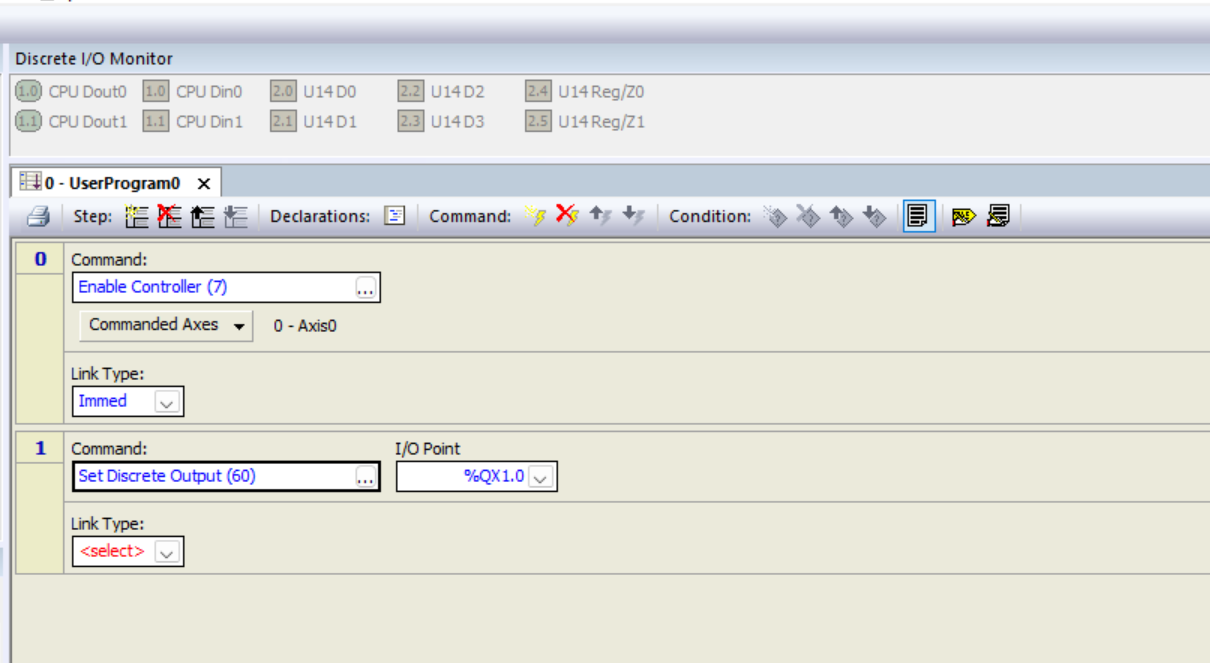
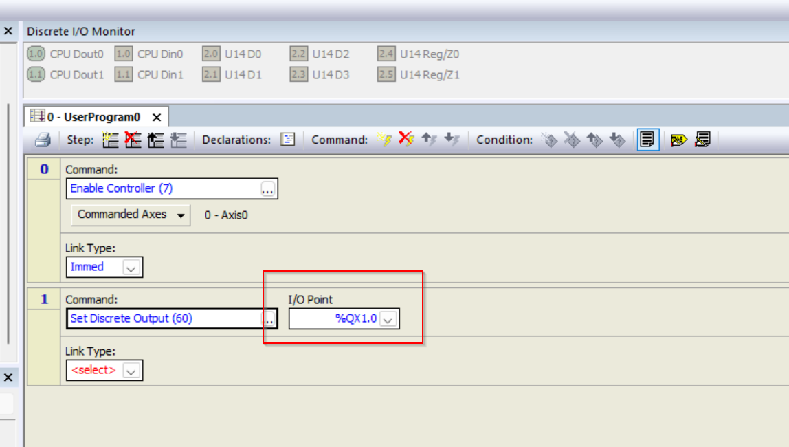
I/O Point allows you to set the output number you want to control for the current Step.
The last step is to set the Link Type, which allows the RMC to specify the conditions under which it will jump to the next step in the user program to begin.During user program execution, the RMC checks the Link Type of the current step at each loop time and jumps to the specified step if the Link Type evaluates to true. The step to jump to is also Ok a valid step number or step label.
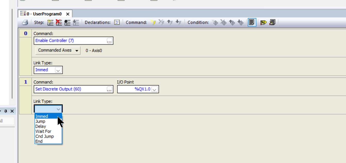
This time, set it to Immed, and Immed will immediately jump to the next step. Now let’s add a new Step by right-clicking on an empty space in the Program Editor and clicking on “Append Step”.
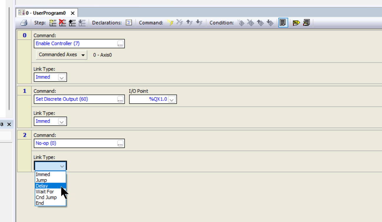
Step2
Now set Link Type to “Delay.” Delay” is an action that waits for the number of seconds specified in the Link Condition Box and then jumps to the step specified in the Jump To Box.
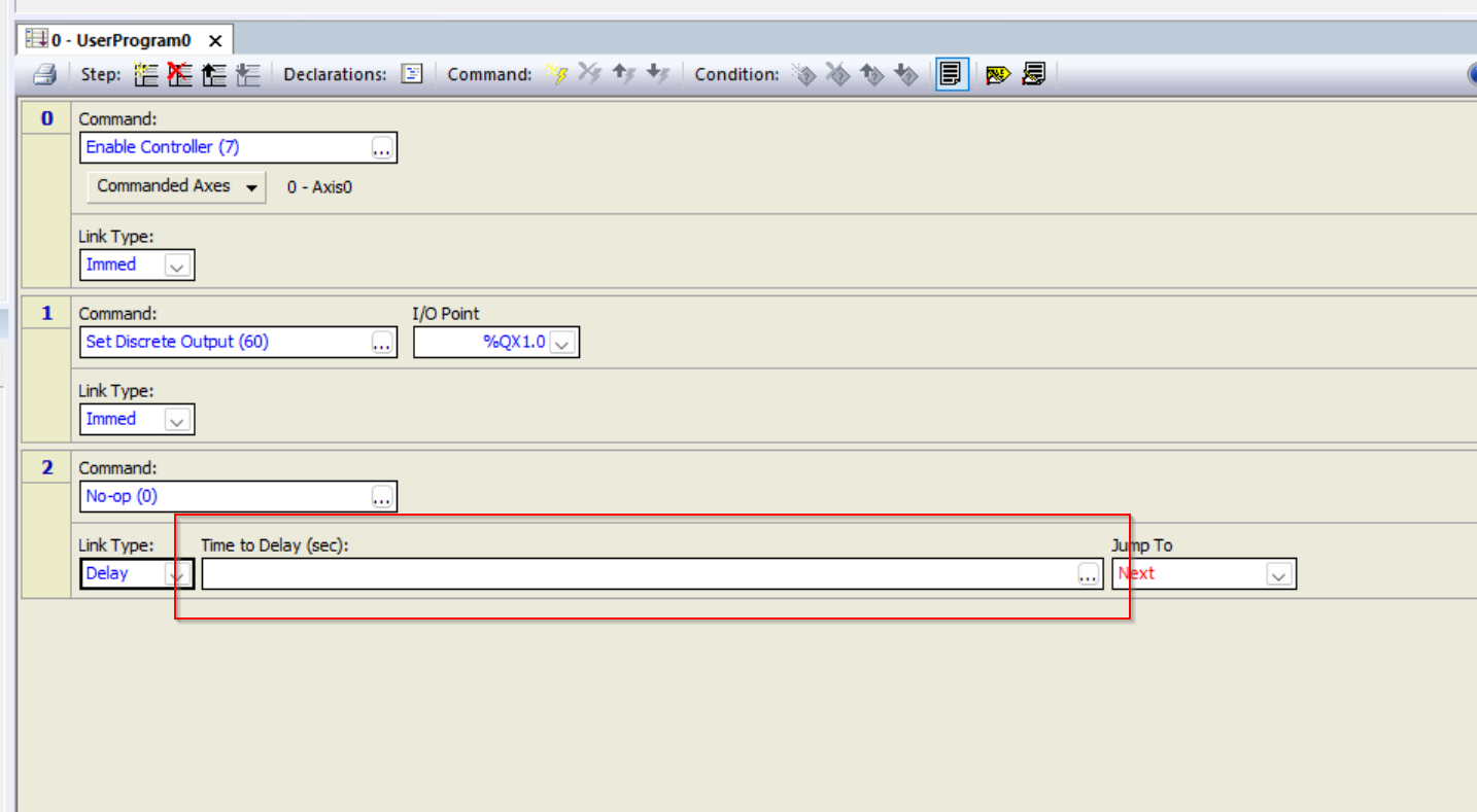
After selecting Delay, an item called Time to Delay (sec) will appear, and the Delay display can be set from this Field.
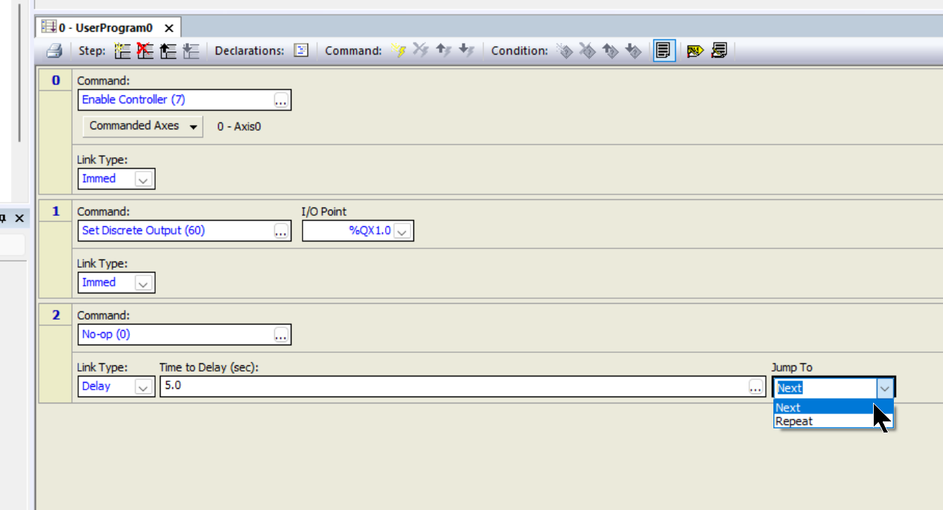
This time, set the delay to 5 seconds, and decide what to do after the 5-second delay from the Jump To Drop-List.
If “Next” is set, it will move to the next Step.
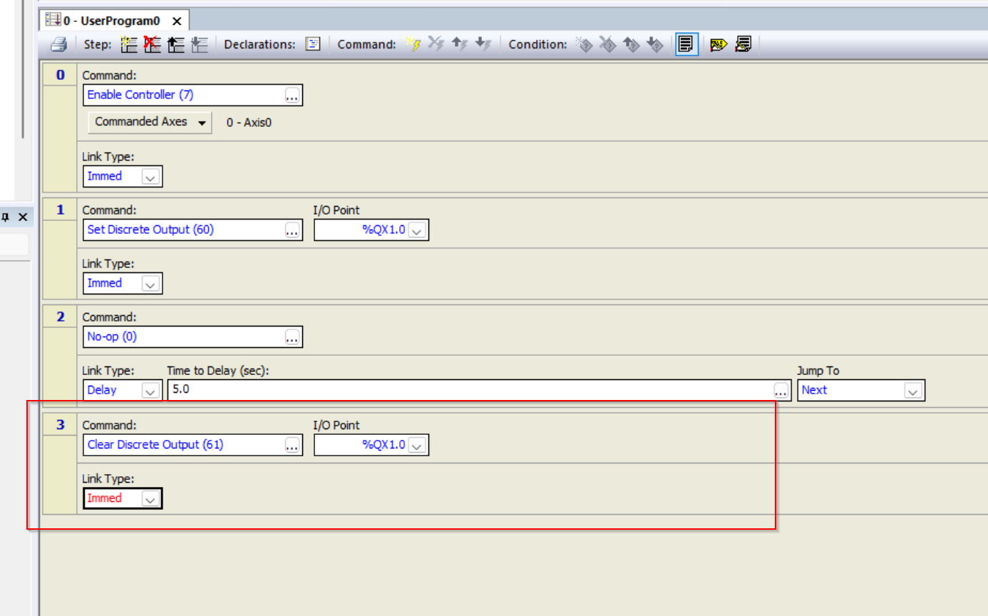
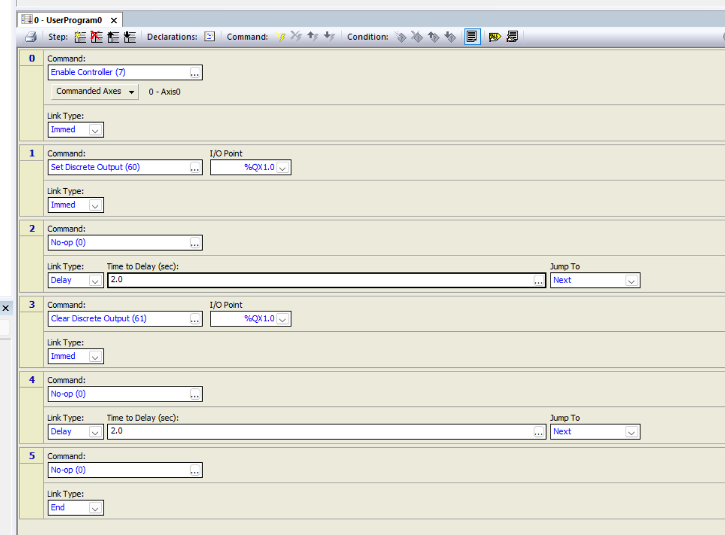
Step3
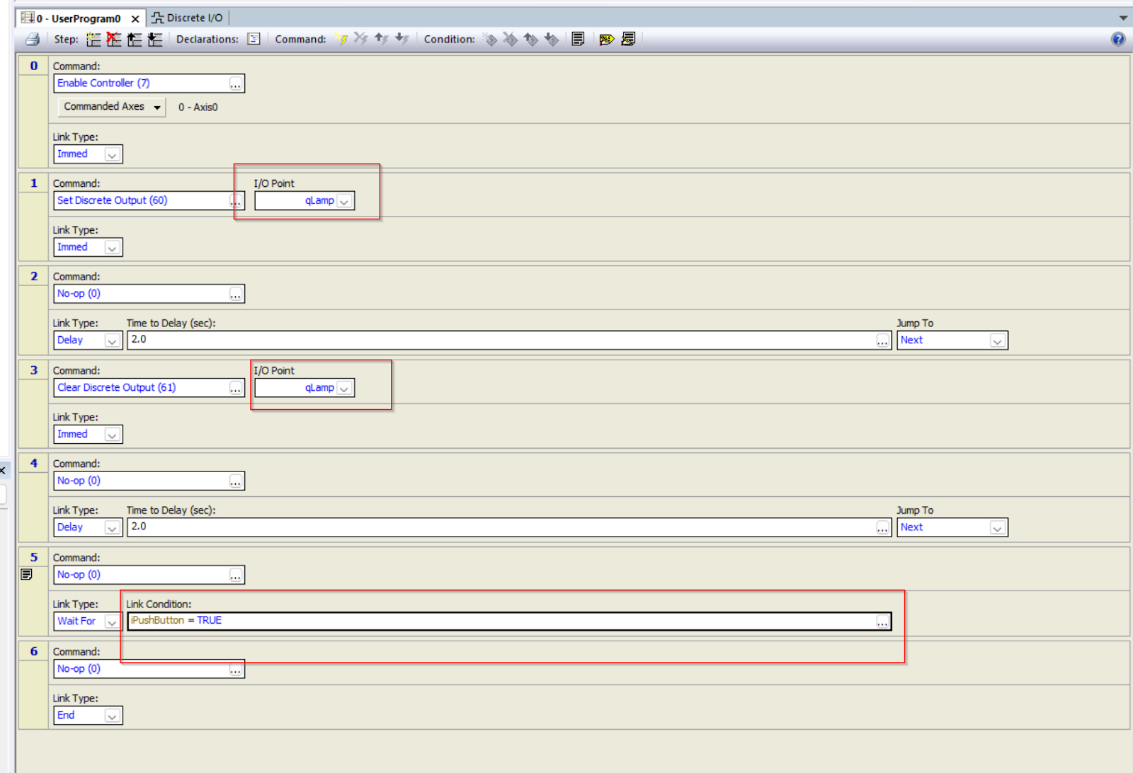
Step 3 adds the command “Clear Discrete Output(61)”.
This command changes the output to false, and the Drop-List of the I/O Point can be set to the IO number to be changed to false.
Step4
Step 4 is a Time Delay as in Step 2.
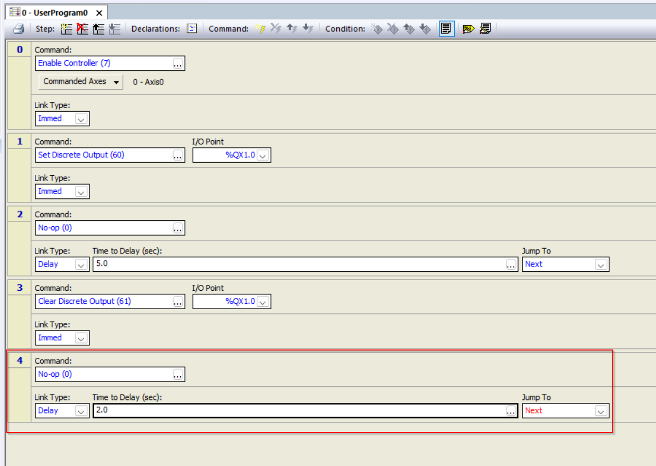
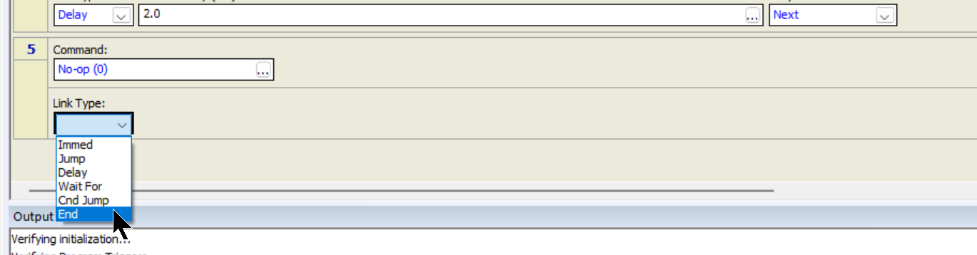
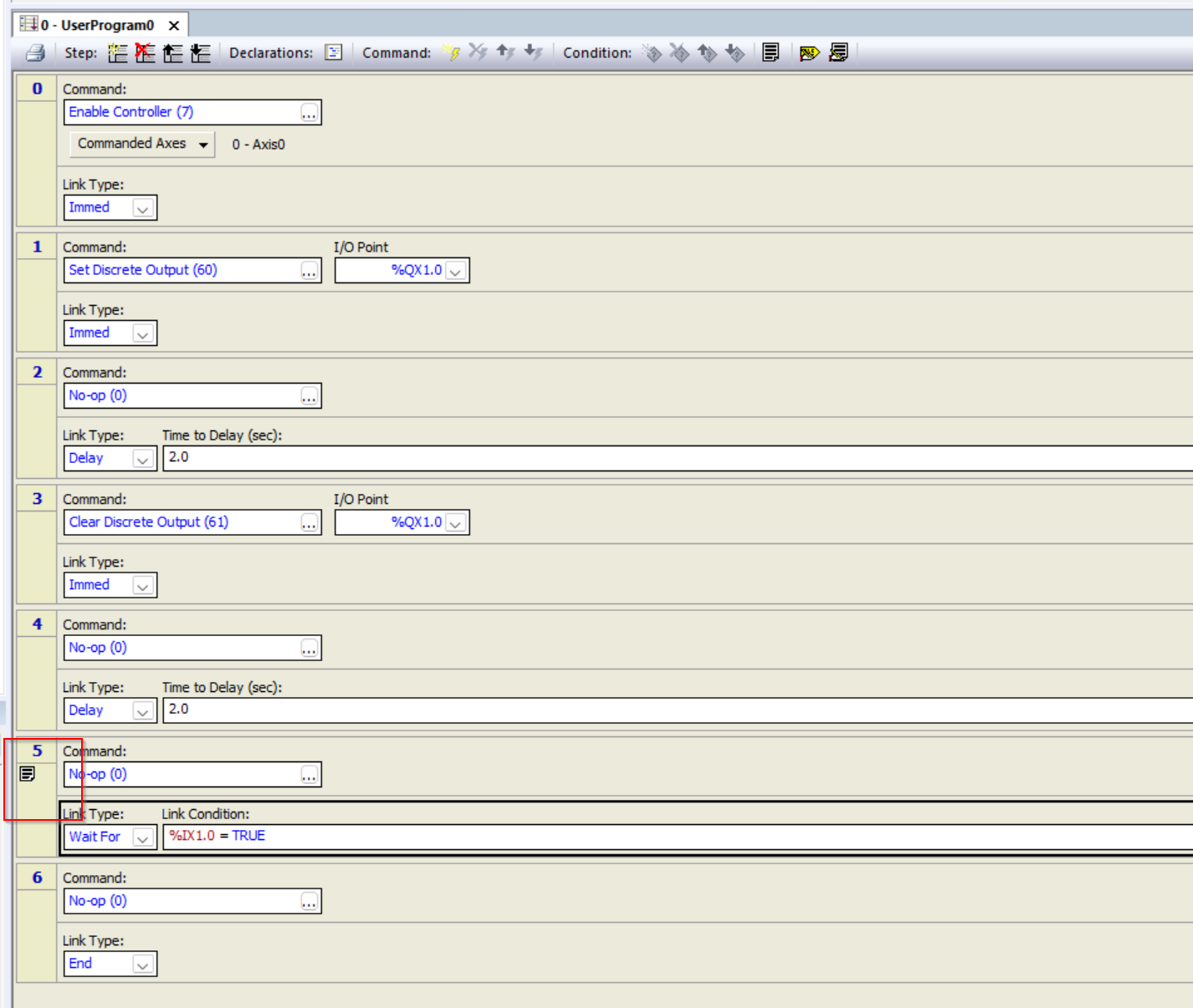
Step5 End
Finally, Step 5 sets the “End” Link Type, and the program ends when the flow transitions to this step.
Finally
This is the UserProgram0.
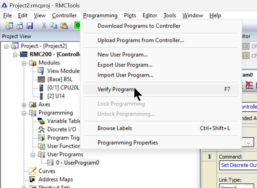
Verify Program
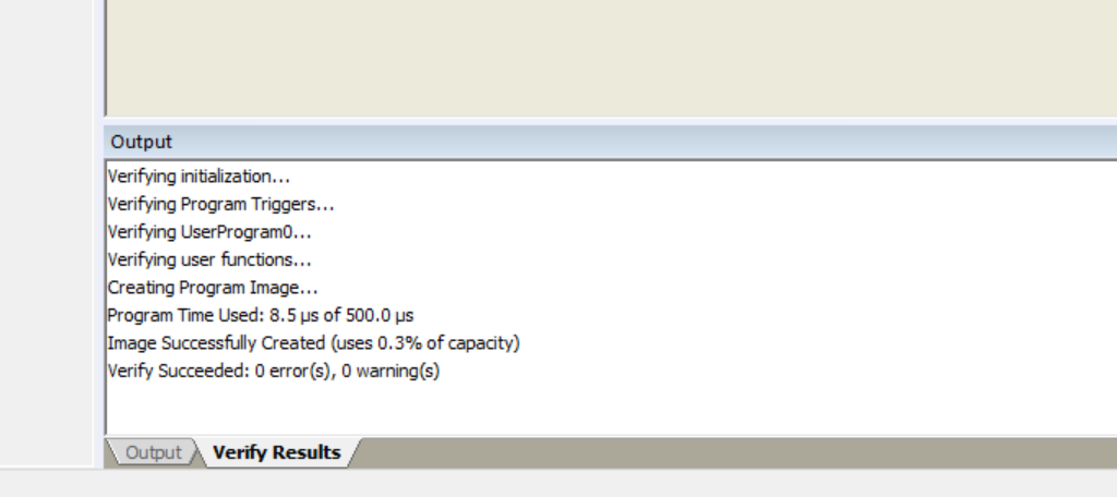
Compile the User Program under Programming>Verify Program.
You can check the compiled results from the Verify Results screen.
Download
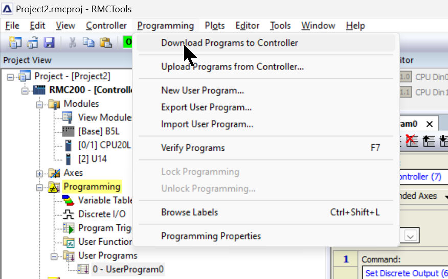
Download the project to the CPU by going to Programming>Download Programs to Controller.
Run Program
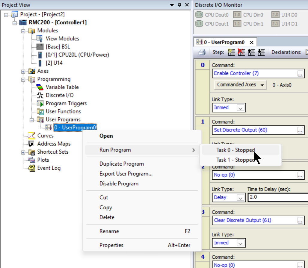
Finally, right-click on the program you want to run>Run Program>Task 0 -Stopped to run the program.
Result
Done!Output is now On/Off.
Program2 Add Wait for
次のプログラムは入力待ちするような制御を追加します。
Add Wait For Step
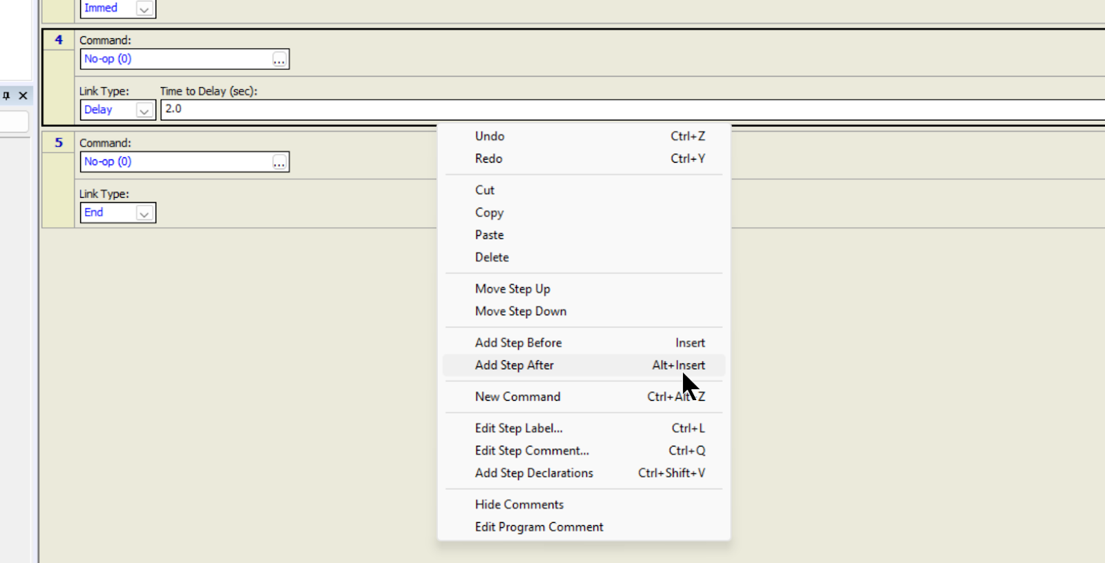
Select Step 4 > right click > Add Step After.
Link Type
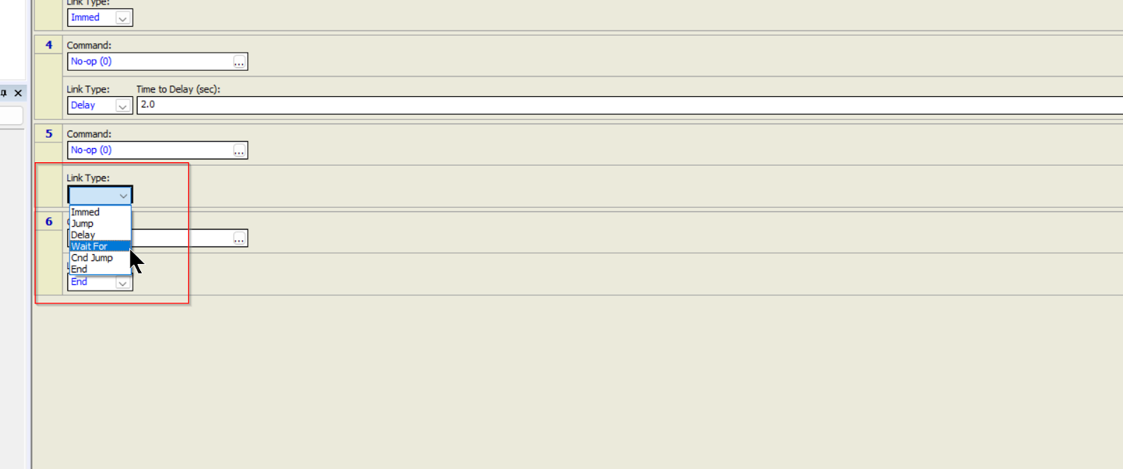
A new Step is added, and “Wait for” is set from the Drop-List of Link Type.
Link Condition
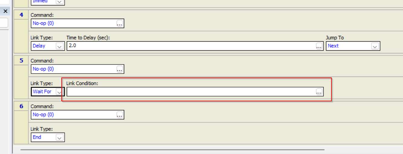
The Link Type of “Wait For” has a Link Condition field.
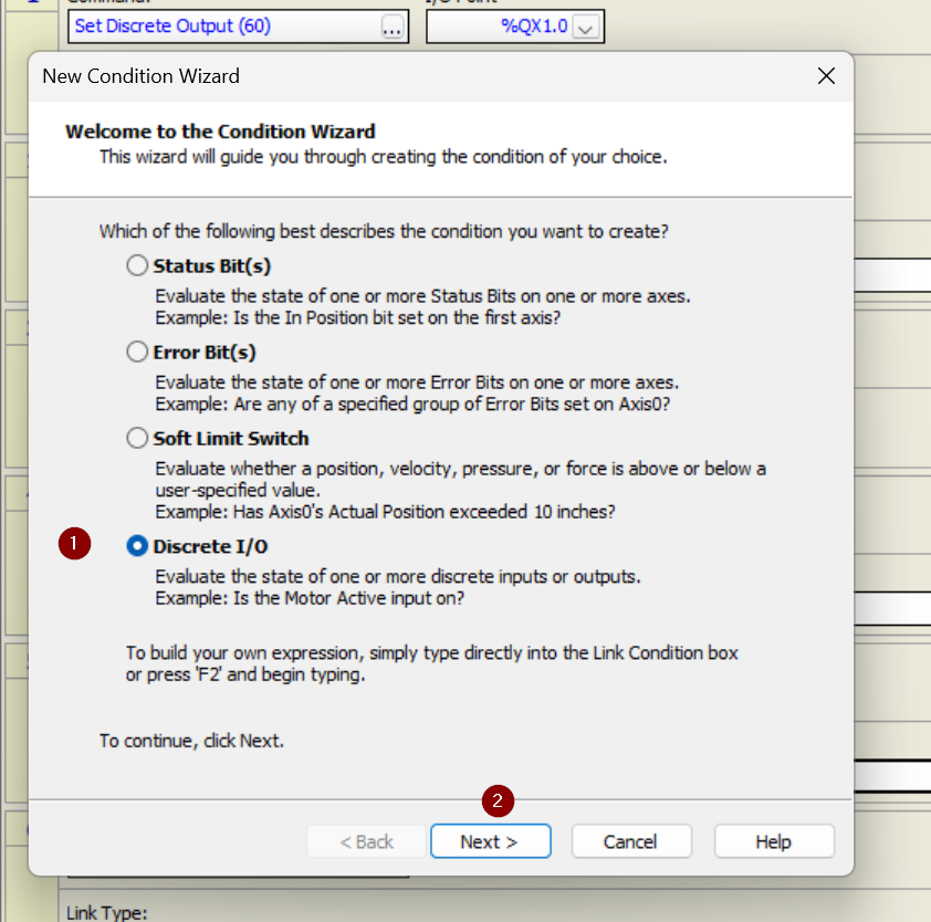
Condition Wizardg appears and allows you to set the conditions for Wait For.
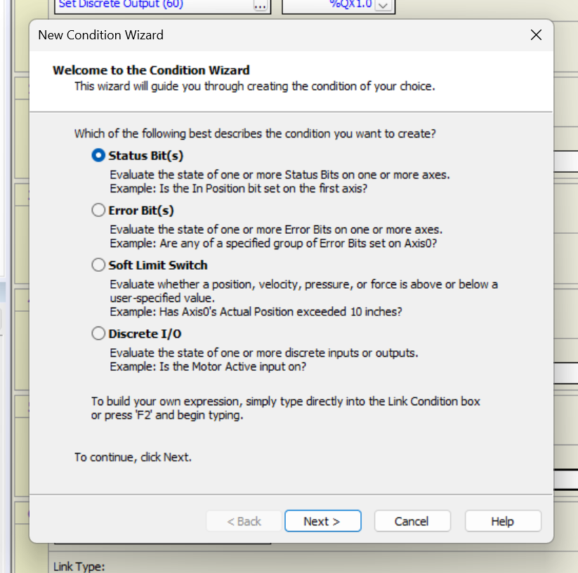
This time, since we are waiting for a digital input signal, select Discrete I/O and press >Next.
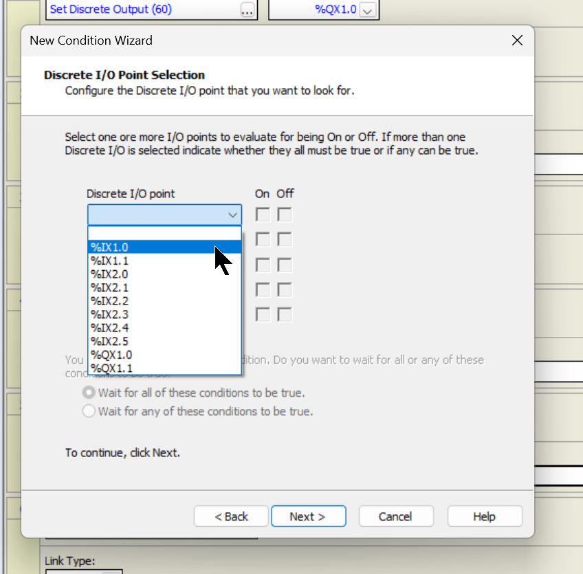
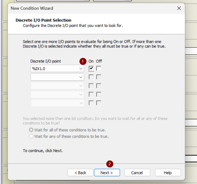
The screen changes to the Discrete I/O selection screen.
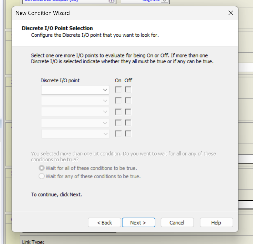
You can select the signal to Wait from the Drop-List. In this case, %IX1.0 is set.
The next step is to set the corresponding signal to either On/Off or wait.
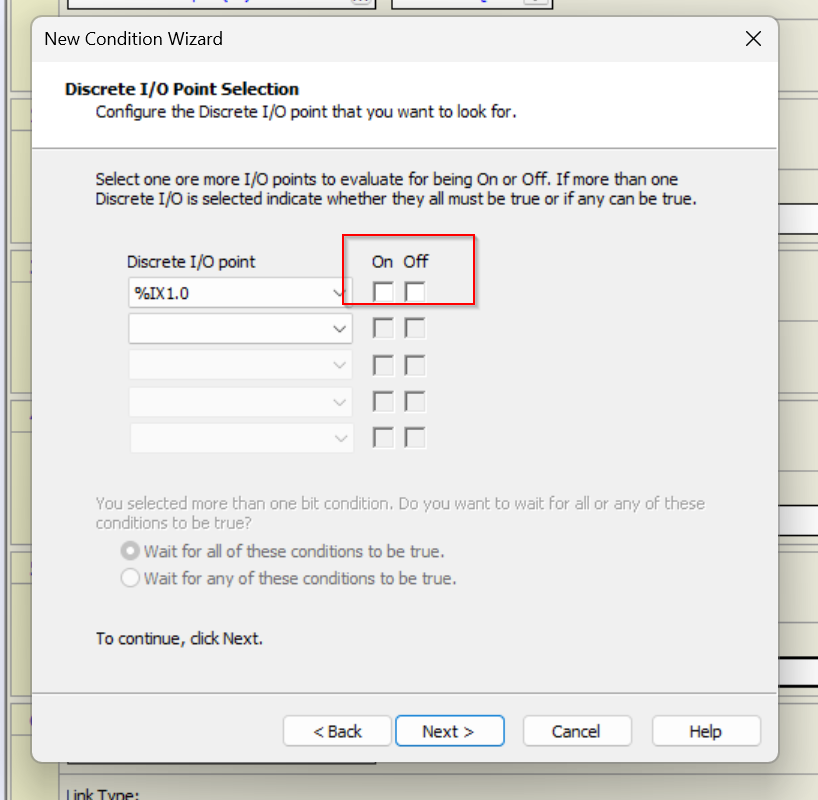
This time, set the %IX1.0 to wait for ON.
Check that the relevant conditions are correct and complete with Finish.
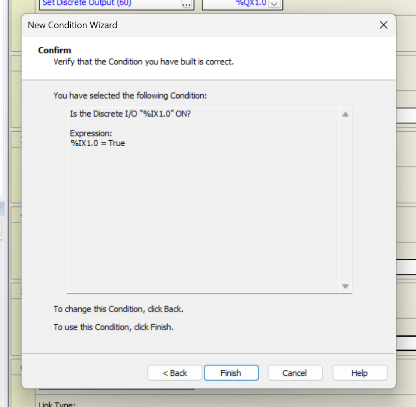
Done!Link Condition is configured.
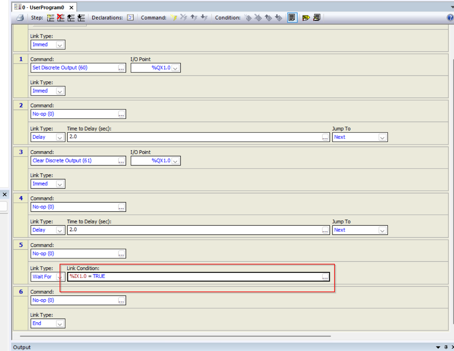
Result
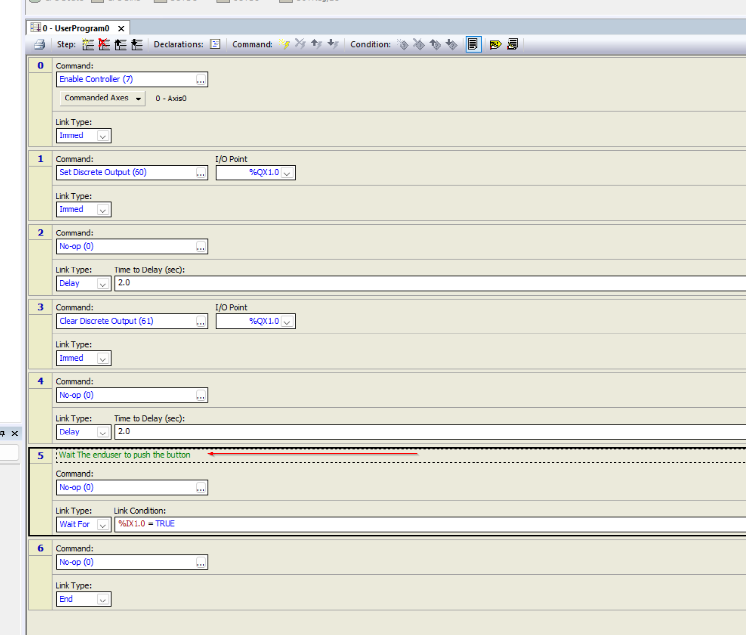
The program now requires Step 5 to set the digital input %IX1.0 to True to proceed.
Add Comment
Adding a comment improves the readability of the program; RMC Tools also has a comment function.
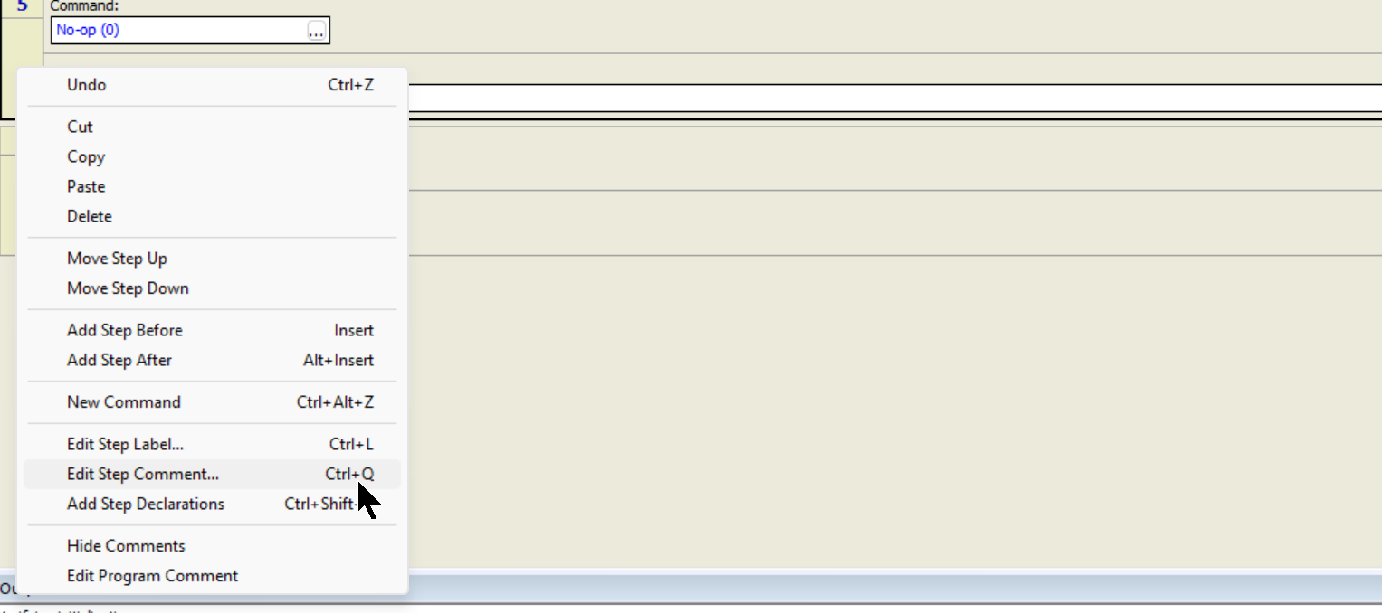
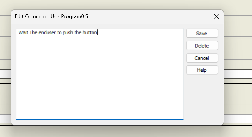
Set Comment to match the behavior of Step.
Done!Comment is added in Step5.
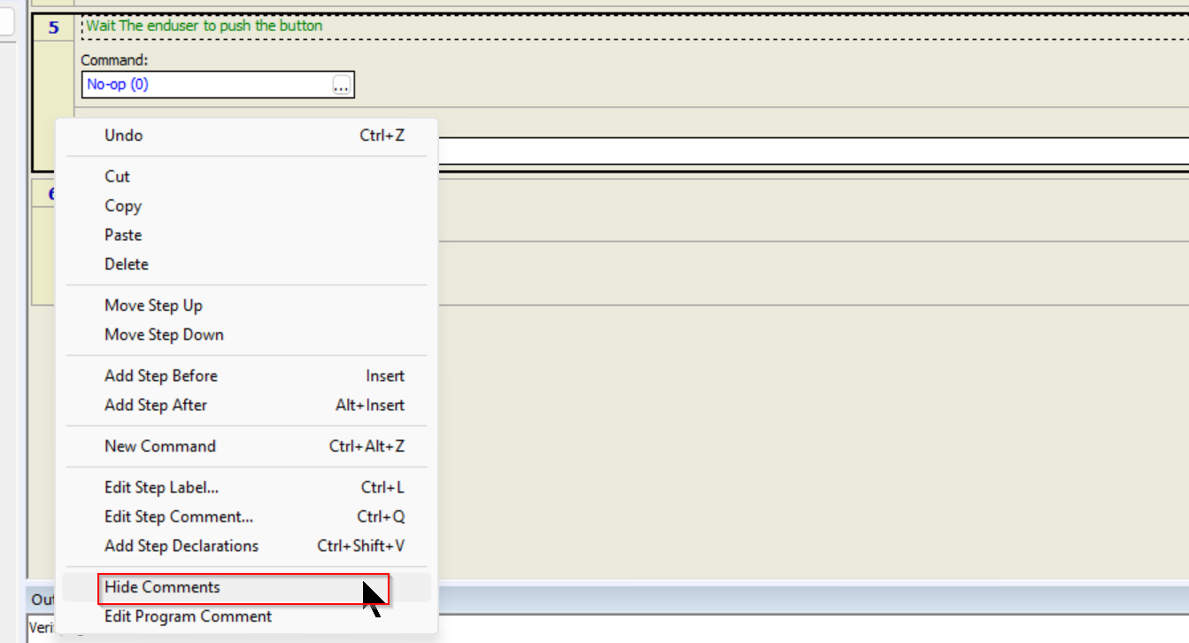
Of course, you can temporarily hide the added Comments by selecting Step > right click > Hide Comments.
Done!
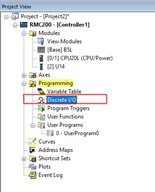
Tag Name IO
To improve program readability, we will now assign “variable names” to the digital inputs and outputs.Click Programming>Discrete I/O.
The Discrete I/O setup screen appears.
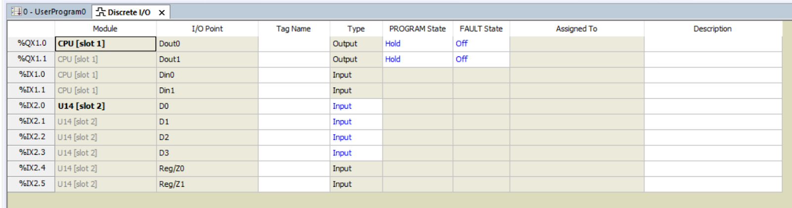
The variable name for each digital input/output can be set in the Tag Name field.
Finally, set the Tag Name according to the application.
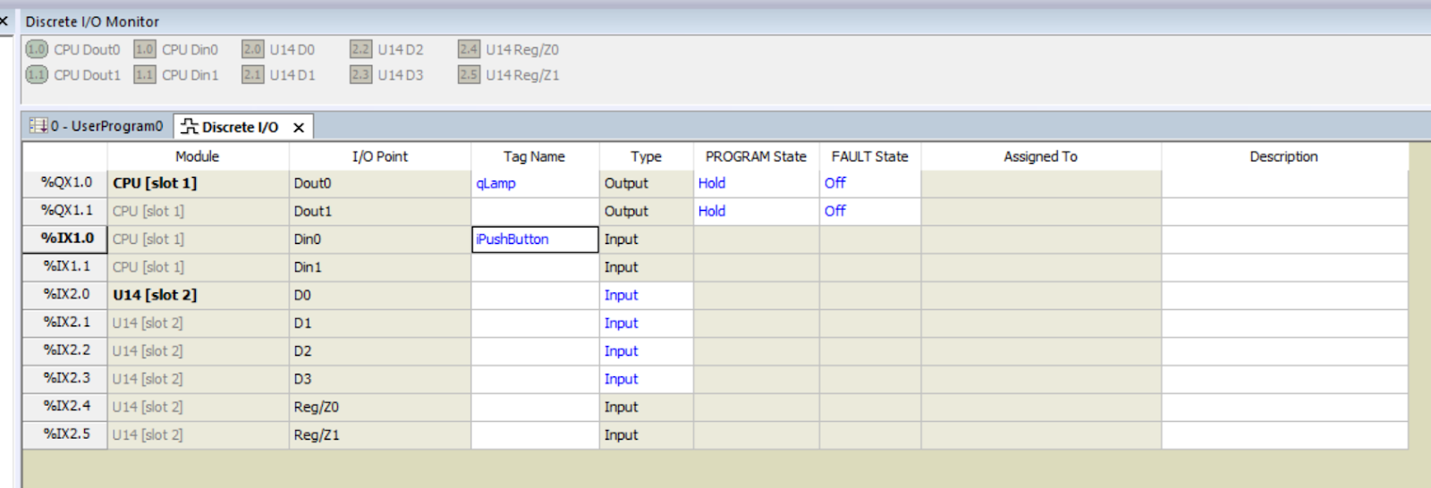
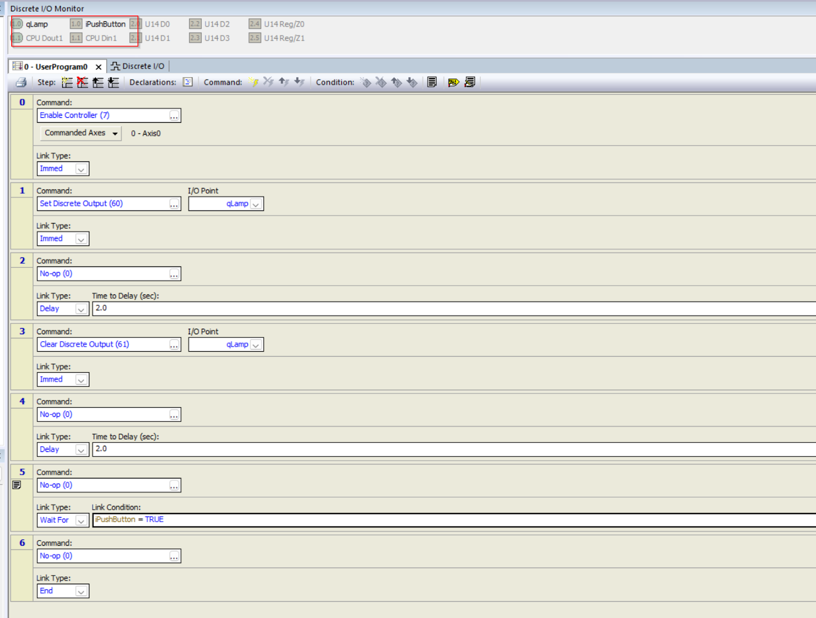
The absolute address that was originally %QX1.0 at the I/O Point in the previous program has been changed to a Tag Name!
Tag Name increases program readability. No more “What is %IX0.0? is no longer a question.
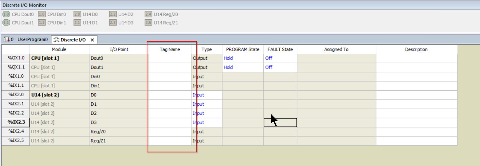
The Discrete I/O monitoring screen above the Program screen now also displays Tag Name instead of absolute address.
IO State
Delta Motion’s Controller can turn each output ON or OFF depending on the CPU status.
PROGRAM State
Hold
If PROGRAM State is set to Hold from the Discrete I/O Settings screen mentioned earlier, the outputs will keep to their last state when the CPU switches to PROGRAM Mode.
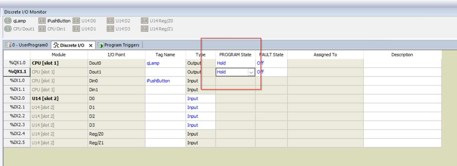
As shown in the figure below, even if the CPU changes to PROGRAM Mode, Dout0 and Dout1 will also keep to the last ON/OFF.
On/Off
Of course, not only Hold, but it is also possible to force the corresponding output to ON or OFF when in PROGRAM state.
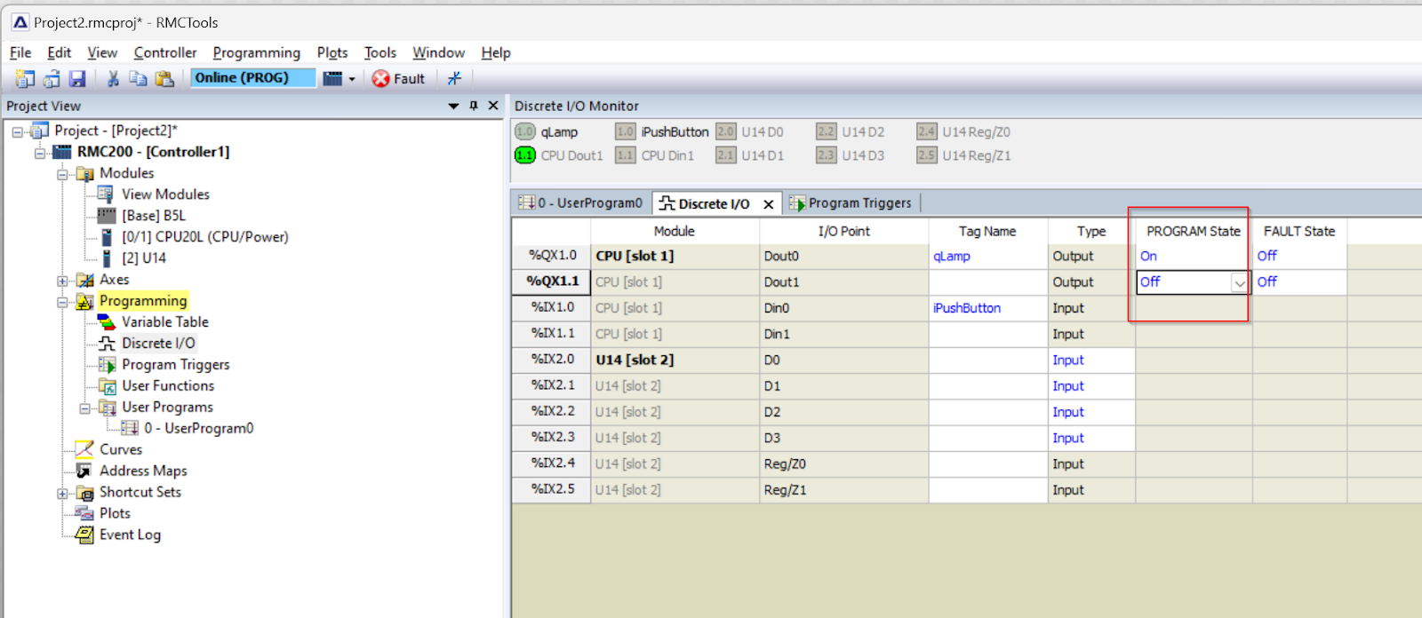
As shown in the figure below, Dout0 turns ON when Program Mode is selected and Dout1 turns OFF when Program Mode is selected.
FAULT State
The RMC CPU can also force outputs to turn ON/OFF when a fault occurs.
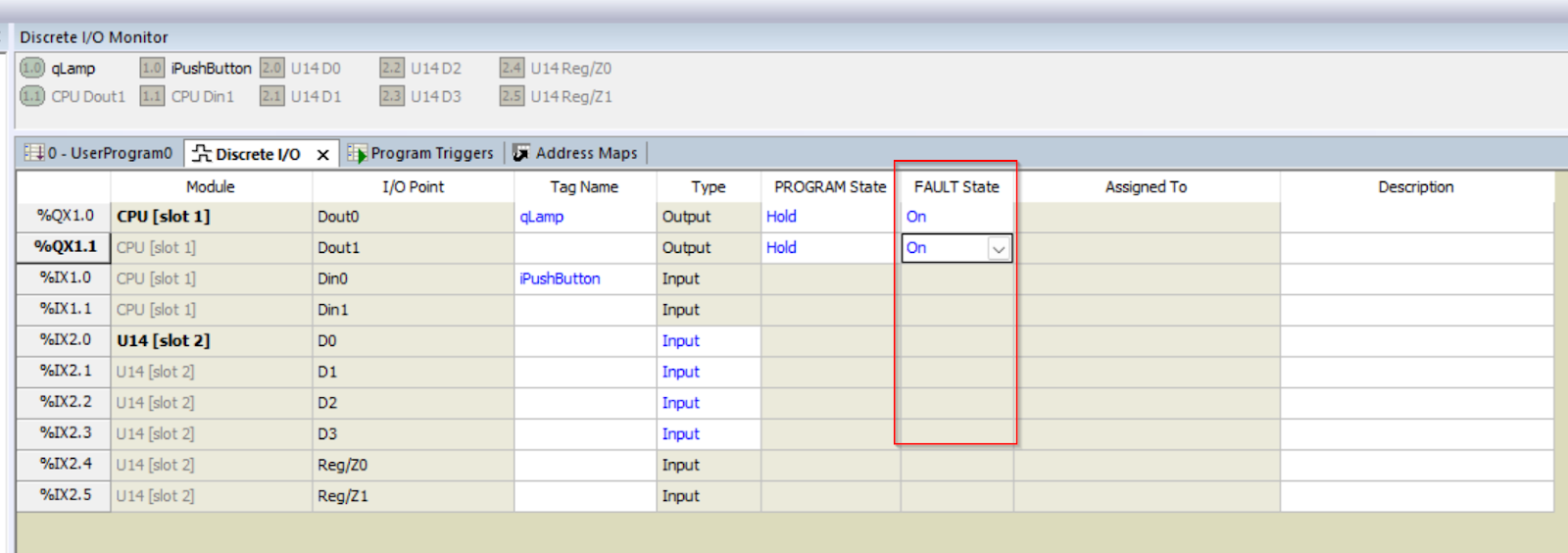
As shown in the figure below, Dout0 and Dout1 are now turned off when they are turned on when in Fault Mode.