This is the second episode of the Tutorial series on DELTA Motion Control’s RM200 Lite – CPU20L. This time we will introduce CPU connection from Ethernet, CPU mode explanation, Discrete Inputs and Outputs.
Let’s get started!
Connect with Ethernet
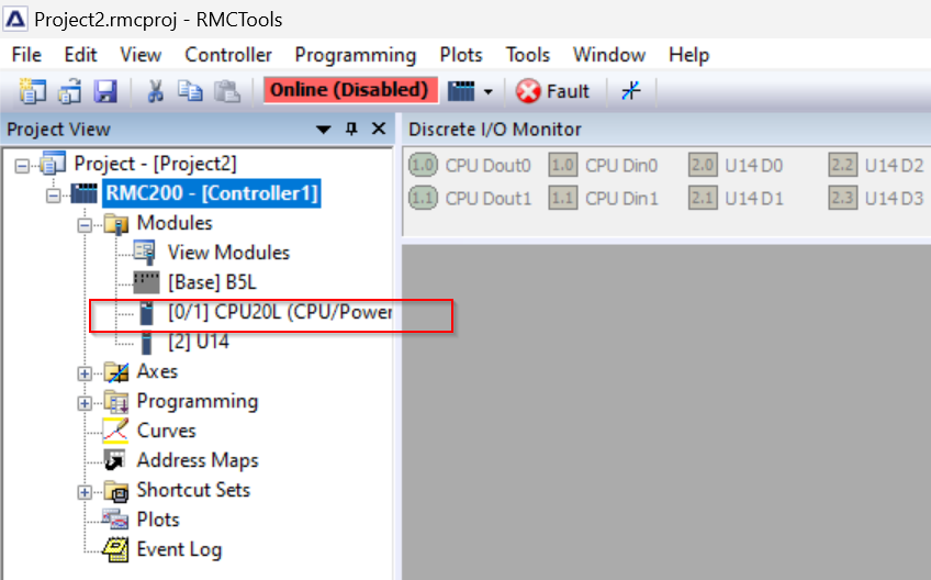
Previously, we connected to the RMC200 via USB, but this time we will access the RM200 via Ethernet: click on RMC200>Modules>[0/1]CPU20L.
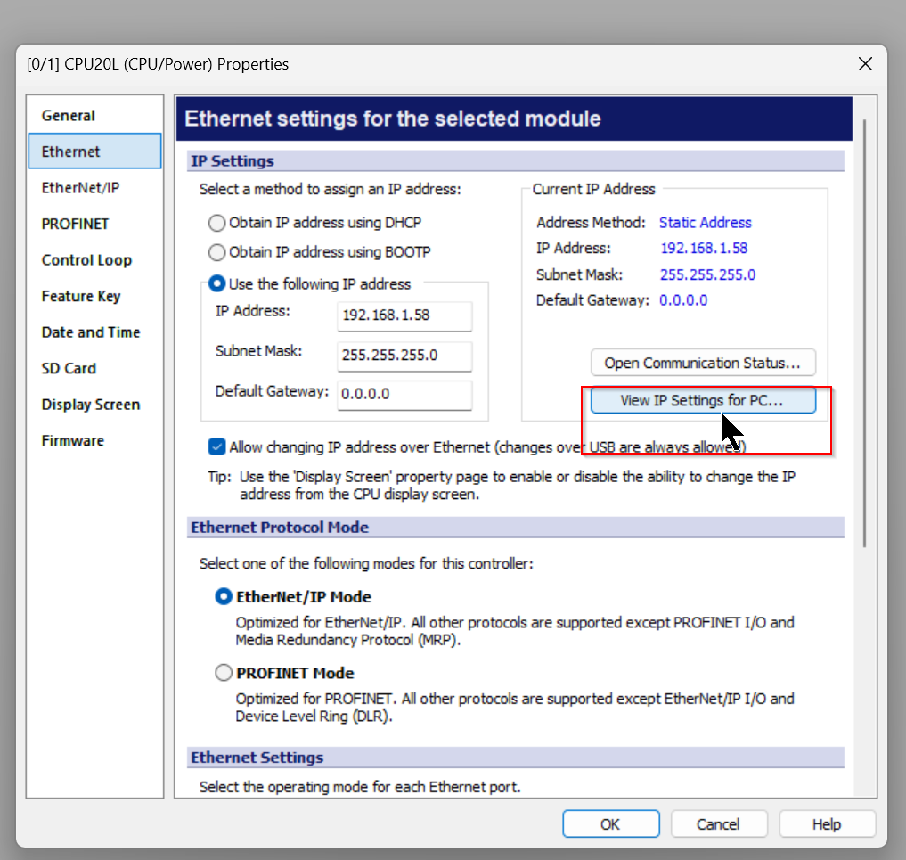
Open the Ethernet Tab.
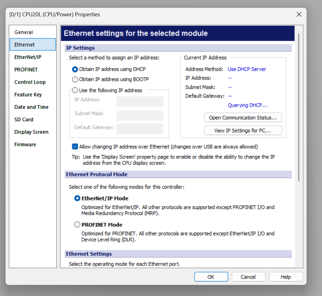
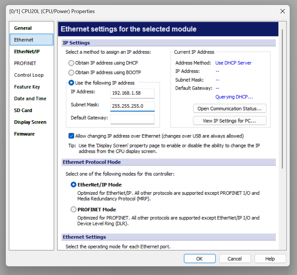
Default is to set the IP address from the DHCP server, but you can set a fixed IP address by selecting “Use the following IP Address”.
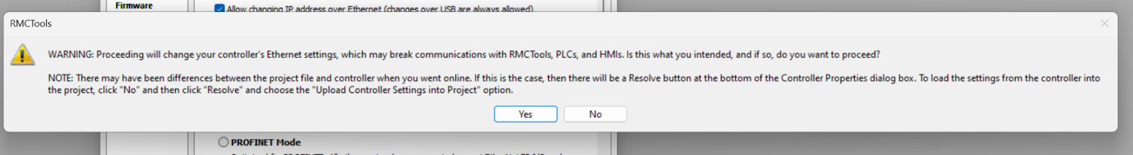
Confirm the setting with Yes.
View IP Setting
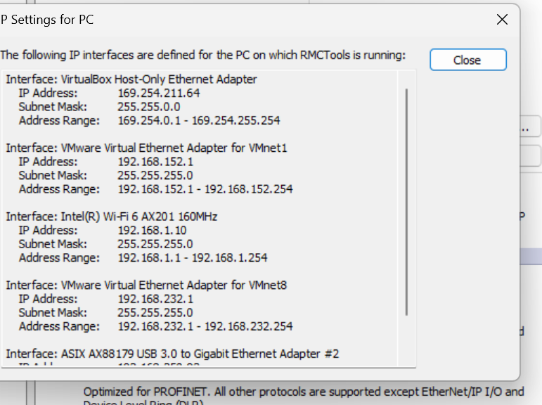
The Current IP Address field displays the current IP address of the RMC200, and by clicking View IP setting from PC, you can also check the IP settings of the PC.
Done!
Download Configuration
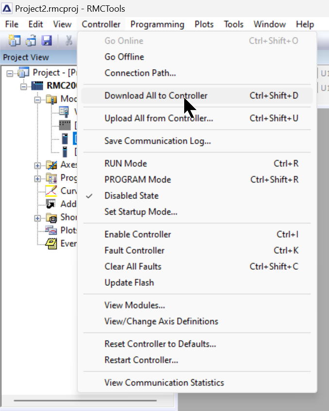
After completing IP settings, etc., download the project to RMC200 by clicking Controller>Download All to Controller.
Connection Path
Next, to access RMC200 via Etherent, click Controller>Connection Path.
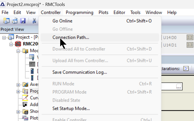
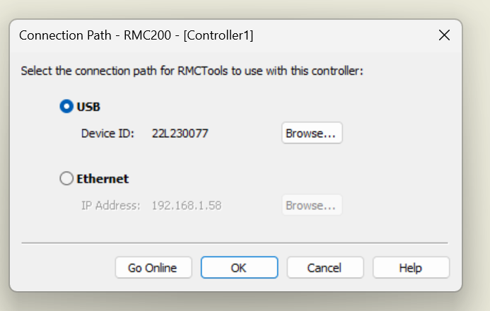
Connection Path can be set for USB or Etherent.
Choose Ethernet>Click Go Online.
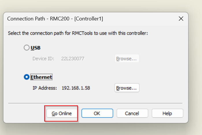
Done!
View From LED Display
You can also check the IP address on the LED Display on the RMC200.
Press the Main Menu>ENTER button.
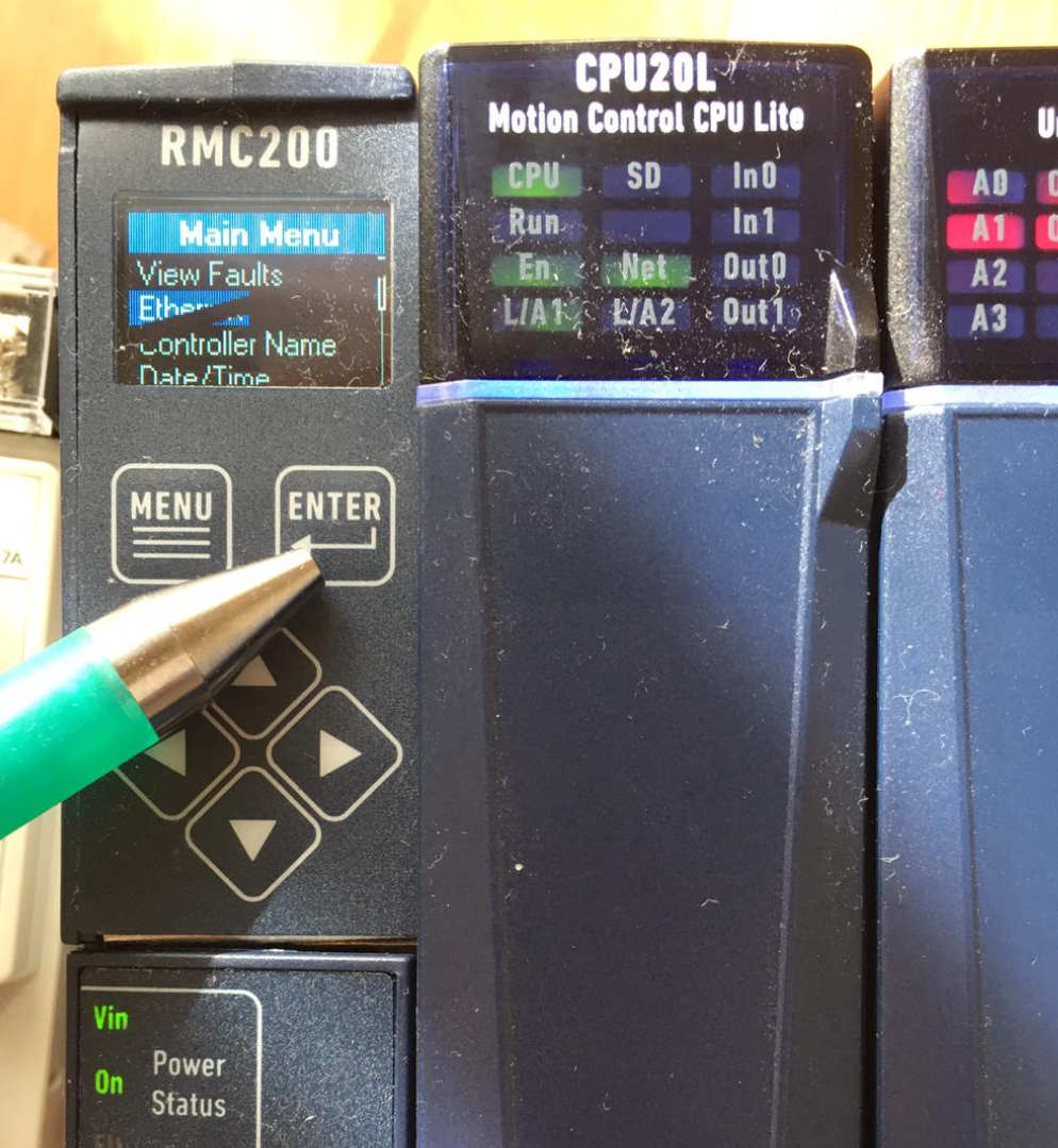
It will change to the Ethernet screen and click ENTER one more time.
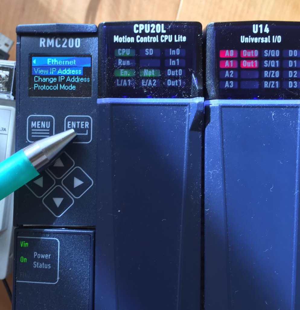
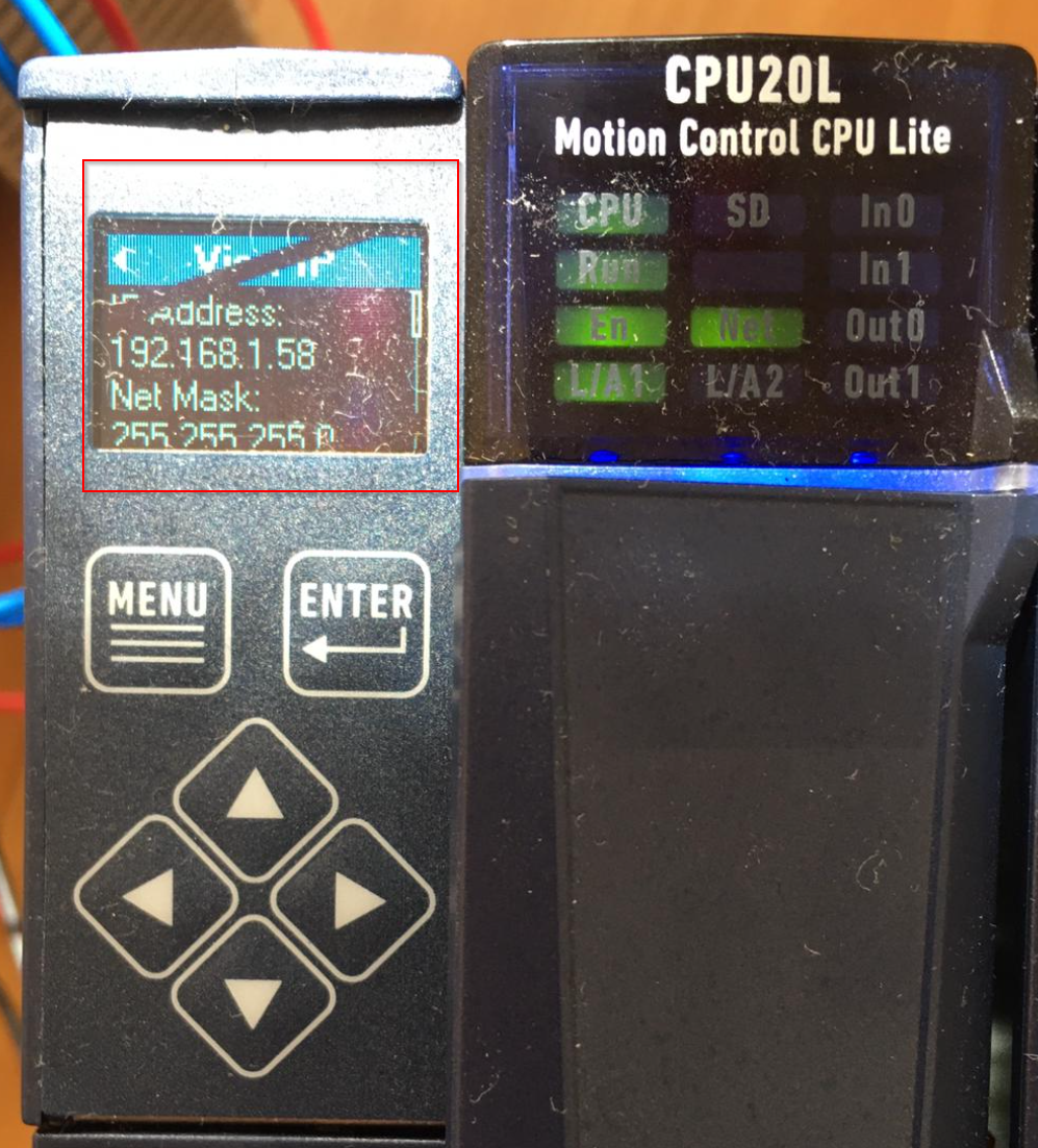
Done!You can currently see the IP address and other settings of RMC200.
Mode
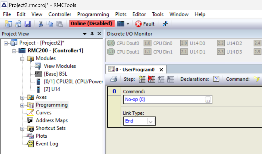
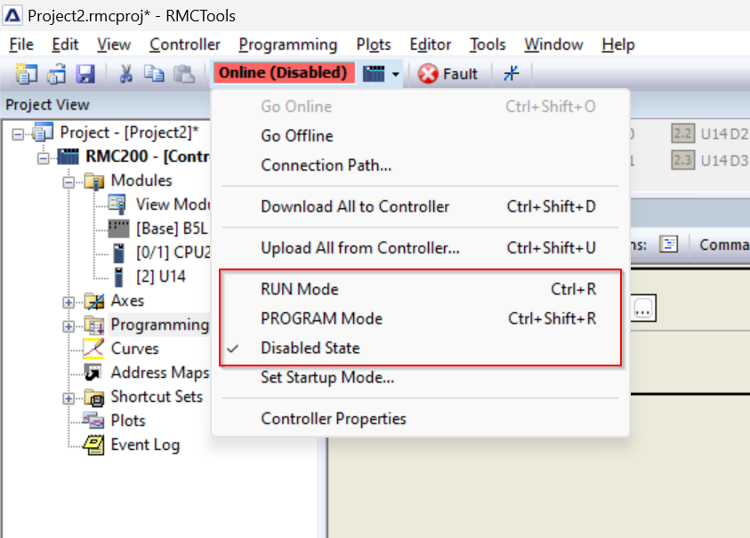
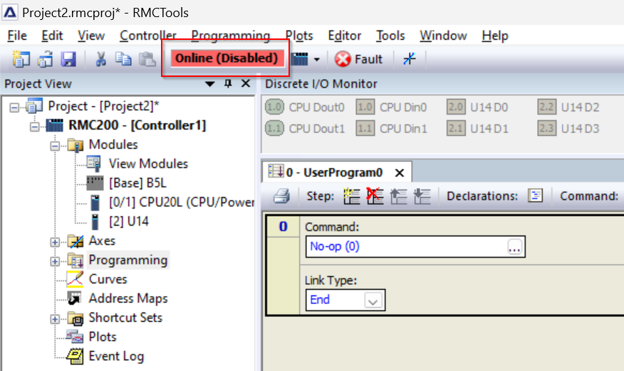
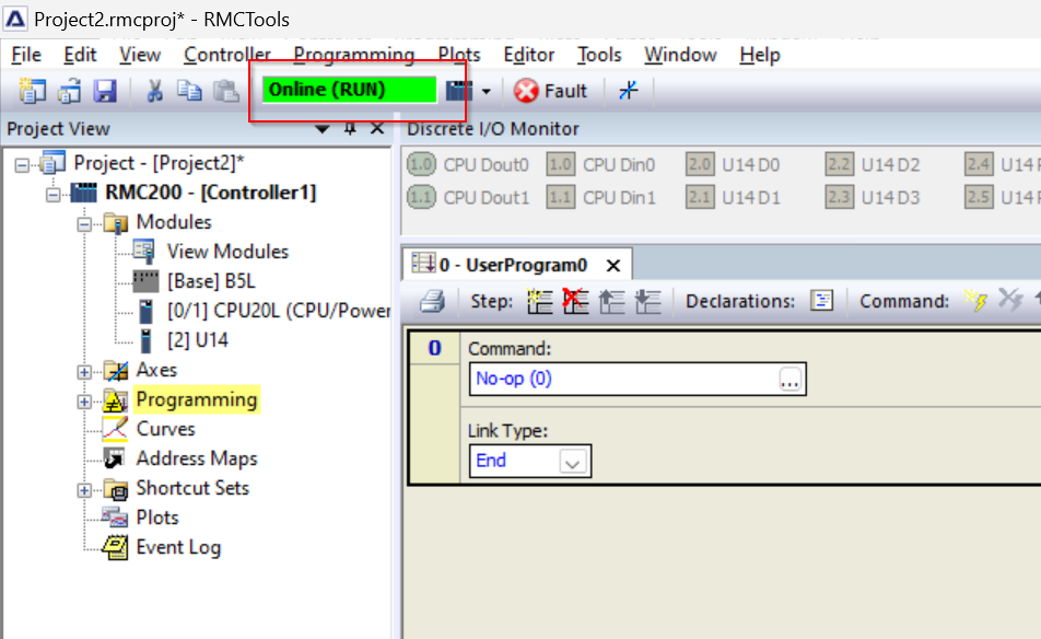
In RMCTools, there is a black text with a red background that says “Online(Disabled)”. This is actually the current mode of RMC200.

Clicking “Online(Disabled)” switches directly to each mode from Menu.
RUN and PROGRAM modes specify whether user programs and program triggers can be executed; RUN or PROGRAM mode does not necessarily affect axis motion.
For example, motion commands can be issued regardless of whether the RMC is in RUN or PROGRAM mode.
The MC200 also has a disabled mode that does not accept motion commands and disables all axes.These modes will now be briefly introduced.
Disabled mode
Disabled Mode is a special mode found only in RMC200.
- All axes are disabled and will not accept motion commands.
- Program triggering is stopped.
- User program cannot be executed.
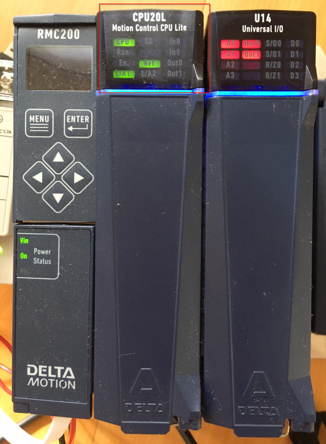
- Run and En LEDs on the CPU body turn off.
- All axes stop at Direct Output Halt.
- Controller Enabled Bit turns OFF.
- Output to be turned on or off when entering PROGRAM mode
Note that once in the disabled mode, the operation is stopped by a direct output stop. In the disabled mode, the axis does not move.
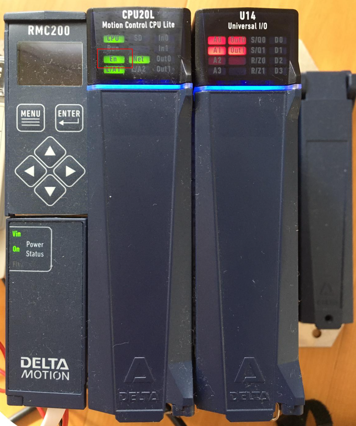
The figure below shows the LED status when RMC200 is in Disabled Mode.
PROGRAM mode
Next is PROGRAM mode, on the RMC200, which is now in PROGRAM mode,
- Program trigger is stopped.
- User program cannot be executed.
- RUN LED is off.
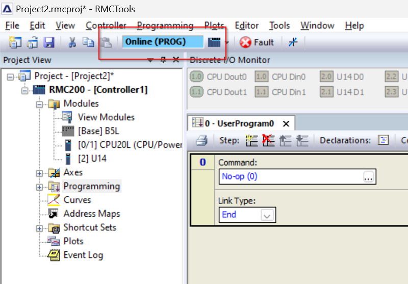
The figure below shows the LED status when RMC200 is in PROGRAM Mode.
RUN mode
The last one is RUN Mode. in RMC200 which is in RUN mode,
- Program triggers are initiated (depending on settings)
- User program can be executed.
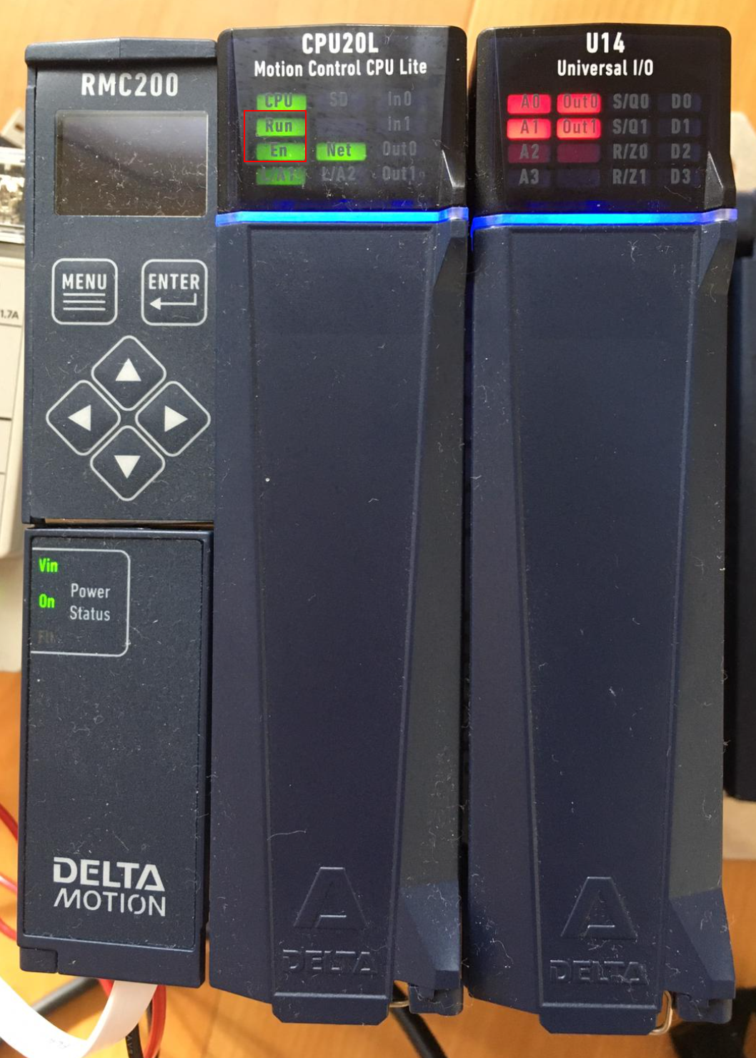
The figure below shows the LED status when RMC200 is in RUN Mode.
Common Commands
The following are a number of commands that are regularly used in RMC200.
Fault Controller
This command can stop all motion of the controller and the RMC switches to Disabled Mode. This will stop all tasks and program triggers and disable all axes. If you want to resend the command, you must put the RMC in Run or Program Mode.
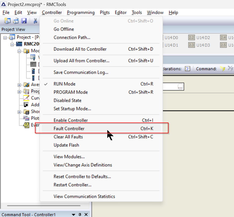
The operation is as shown in the figure below.
Enable Controller (7)
This command will be enabled for all axes of the RMC and is normally used after the RMC is started.
The mode of the RMC will be PROGRAM Mode.
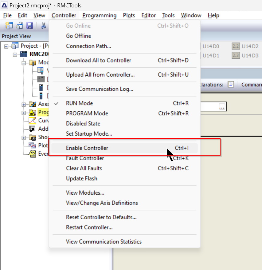
The operation is as shown in the figure below.
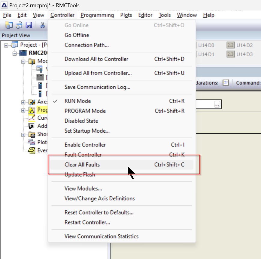
Clear Faults (4)
This command can clear all held error bits. It is then useful to clear faults to see which conditions have been resolved.
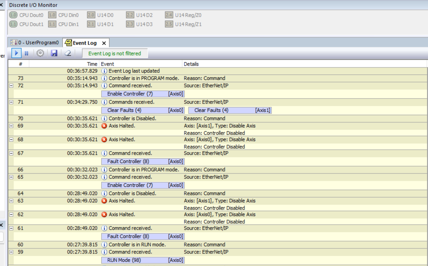
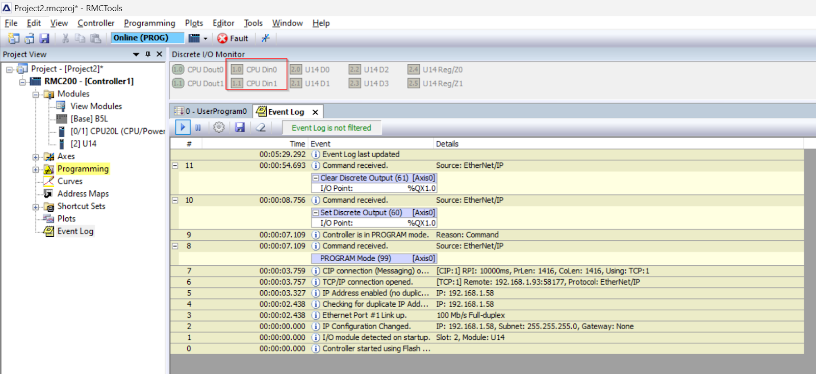
Event Log
RMC200 stores events that occur inside the CPU as history, and past events can be viewed from the Event Log.
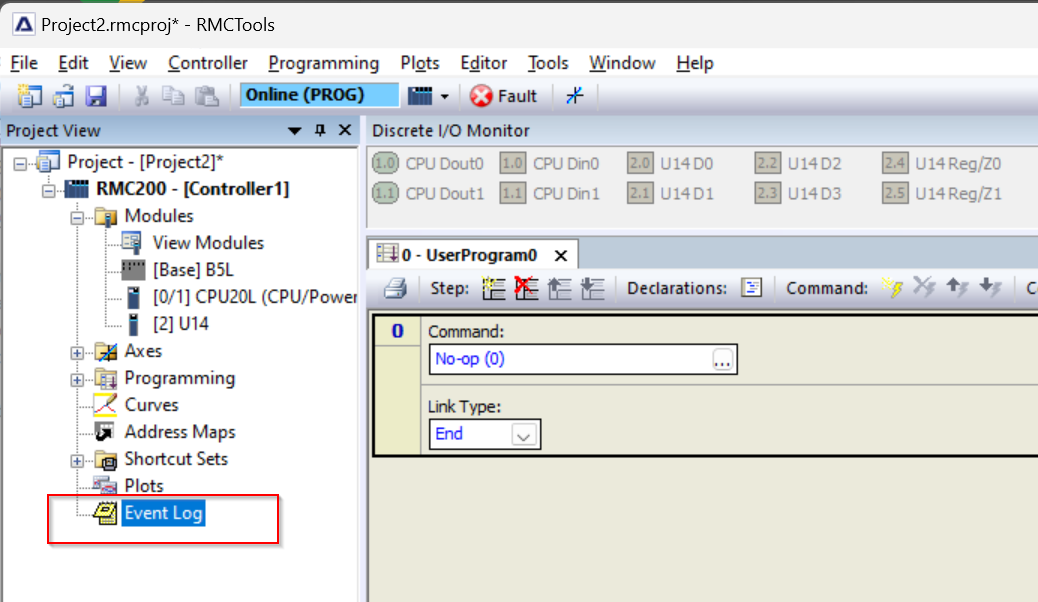
The figure below shows the result.
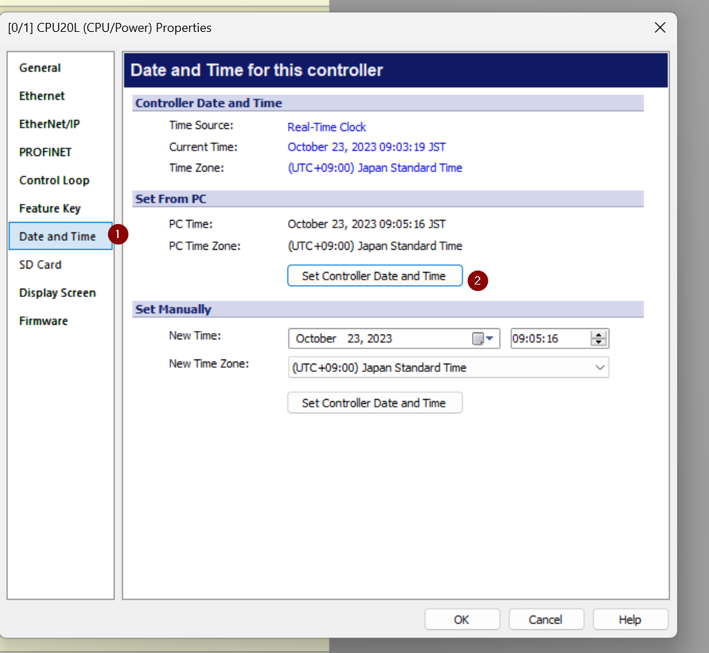
Time Setting
If the Event Log time does not match the actual time, it will be difficult to track errors, etc. Change the CPU time.
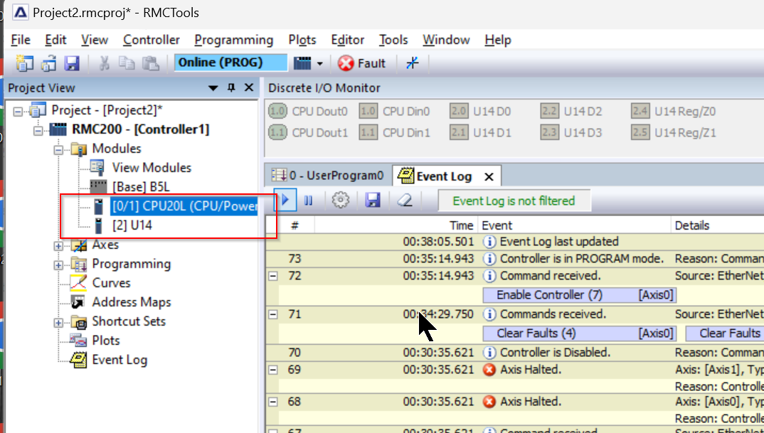
Click on Data and Time>Set Controller Data and Time.
Discrete Inputs
The last section monitors the inputs and outputs on the RMC200 CPU20L main unit.The Discrete input of the CPU20L supports signal levels from 12 to 24 VDC and consumes a maximum of 3 mA. Each input is individually isolated.
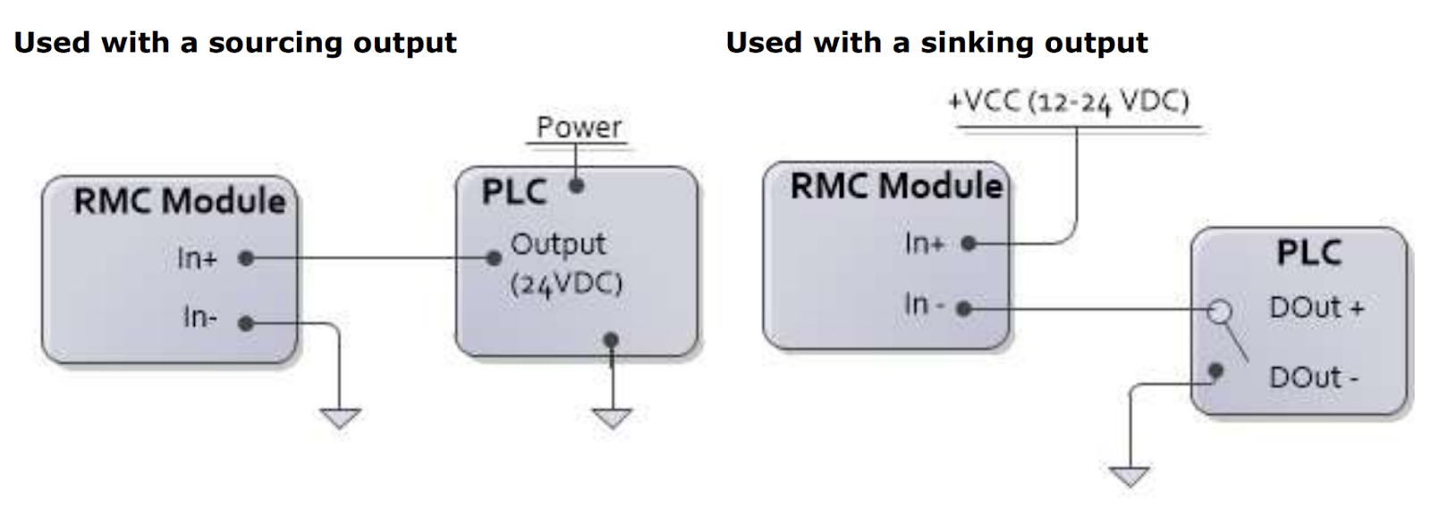
CPUDin0 and CPUDin1 are available on the Discrete I/O Monitor screen, and their ON/OFF status can be checked directly.
You can check the operation from this video.
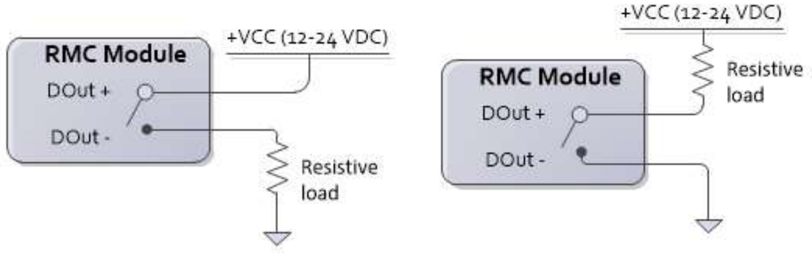
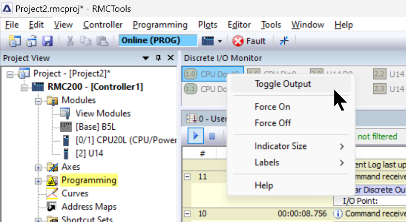
Discrete Outputs
The CPU20L’s Discrete Output is solid state relays, high impedance in the off state and low impedance in the on state (8 Ω maximum, 5 Ω typical). The output can be wired in high-side or low-side configuration, with a maximum current of 75 mA and a maximum voltage of 30 V.
Right-click on CPU Dout0 to toggle output or force output.
You can check the operation from this video.