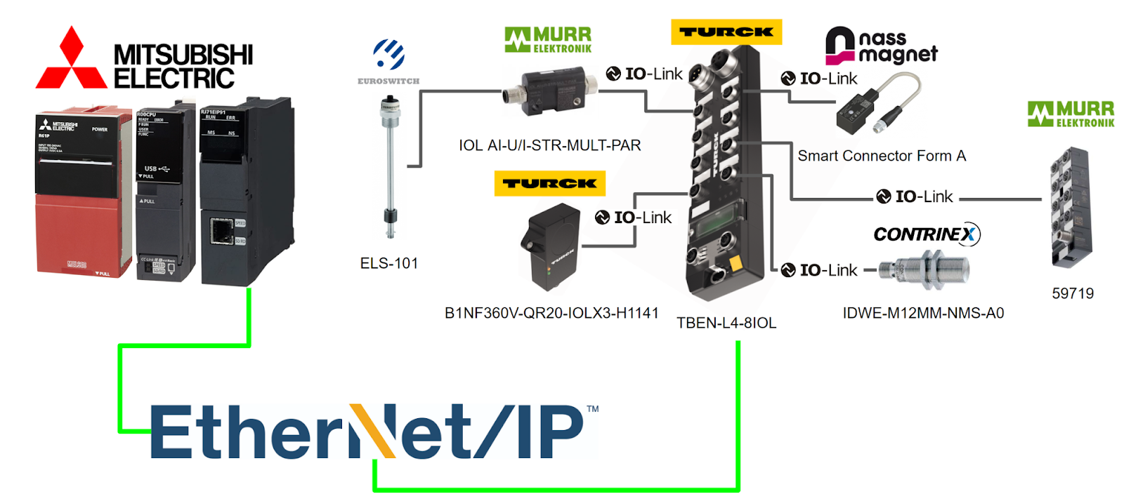
In this article, Mitsubishi IQ-R R00CPU and RJ71EIP91 Ethernet/IP module are used to connect to TURCK’s IO-Link Master via Ethernet/IP.
IO-Link devices will be from Murrelekronik, TURCK, Nass magnet and Contrinex.
Let’s get started!
Reference Video
Reference Link
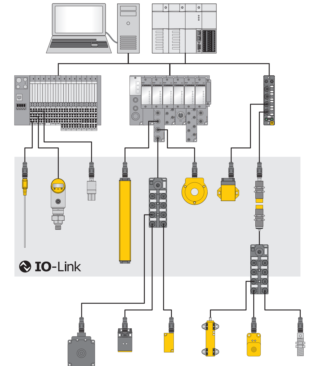
System architecture
IO-Link communication requires at least one IO-Link master and one IO-Link device (e.g., sensor or actuator), which are interconnected with an unshielded 3-wire or 5-wire standard cable.
Settings related to IO-Link can be made using the configuration tool or at the fieldbus level.
The IO-Link master establishes the connection between the IO-Link device and the host control system. Note that an IO-Link master can have multiple IO-Link ports, but only one IO-Link device can be connected to each port.
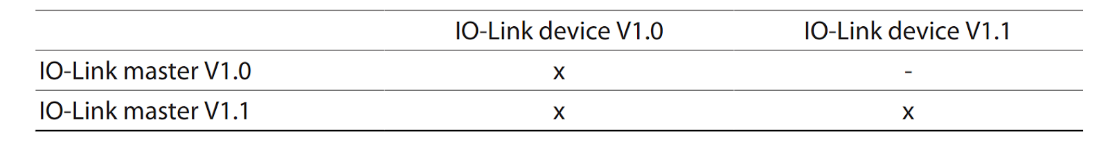
Combining IO-Link devices with different specifications
Only devices of specification V1.0 can be operated by an IO-Link master of specification V1.0.
Conversely, devices of specification V1.0 and V1.1 can be operated by an IO-Link master of specification V1.1.
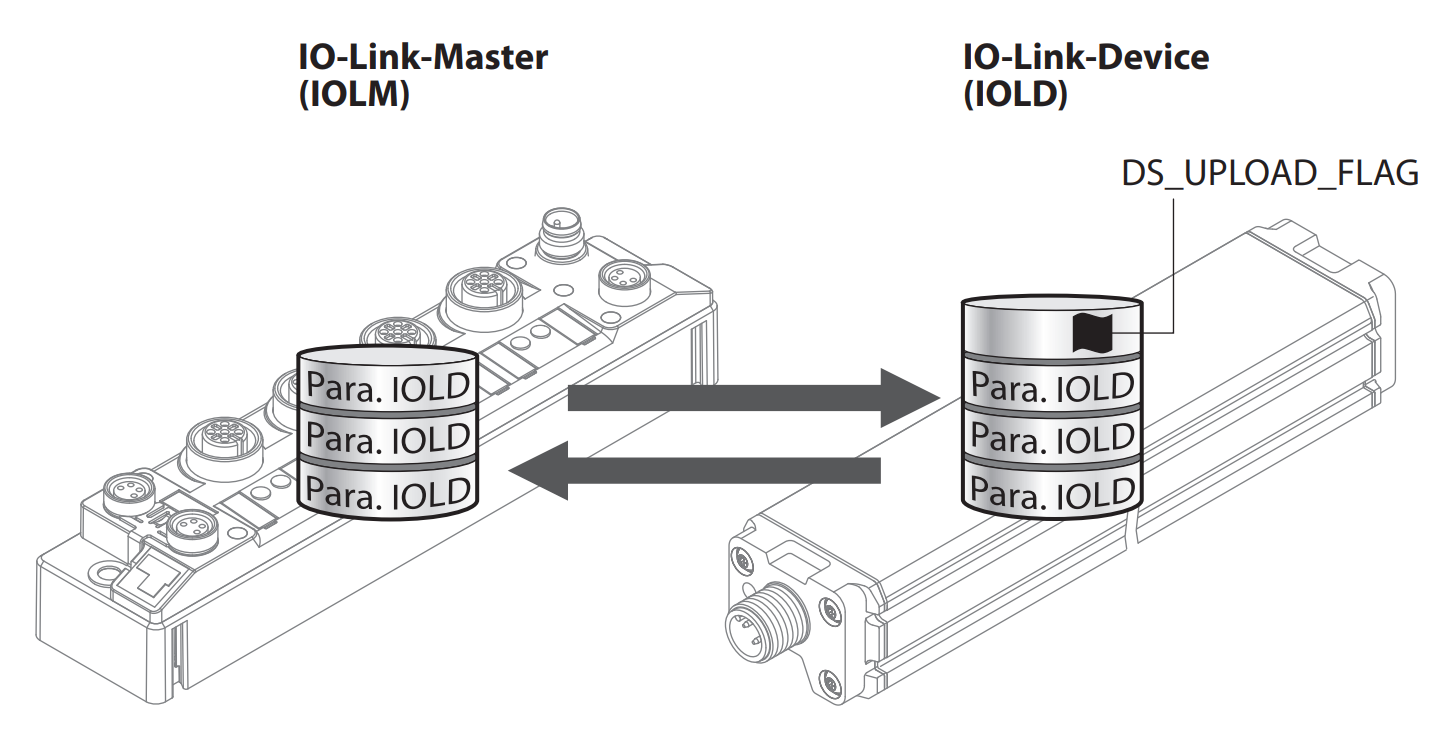
Data storage mode
Data storage mode provides the convenience of replacing IO-Link devices without the need for reconfiguration.
The IO-Link master or IO-Link device can save the device parameters set in the previous configuration, and the parameter data memory of the IO-Link master and IO-Link device are synchronized.
If data save mode is enabled, when a device is replaced, the master writes the stored device parameters to the new device. The application can be restarted without having to perform a new configuration.
Note that the data storage mode is only available for devices compliant with IO-Link specification V1.1.
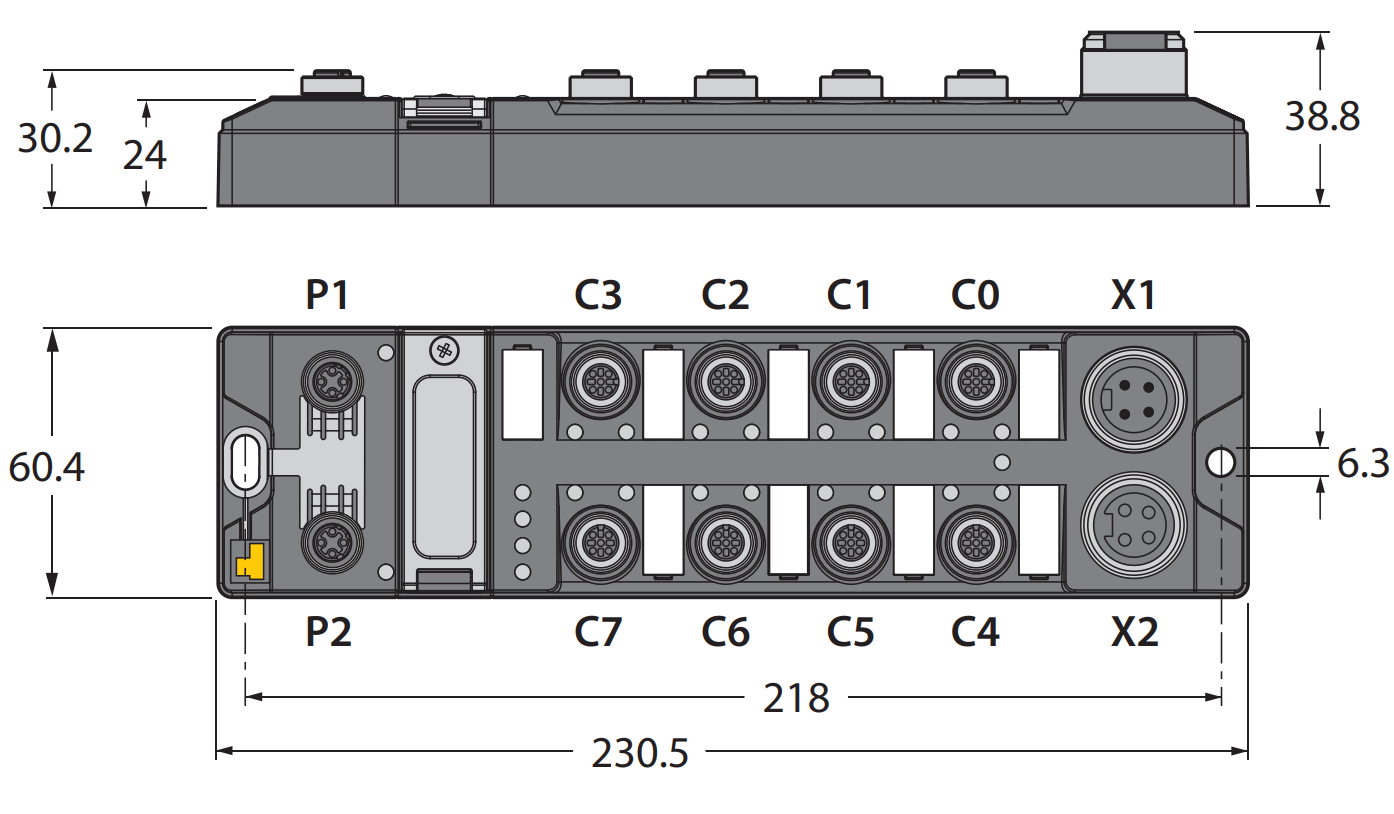
TBEN-L4-8IOL4
Designed with a fully sealed housing with TBEN-L4-8IOL4 protection class IP65/IP67/IP69K.
- TBEN-L…-8IOL
- Eight IO-Link ports are provided for connecting IO-Link devices.
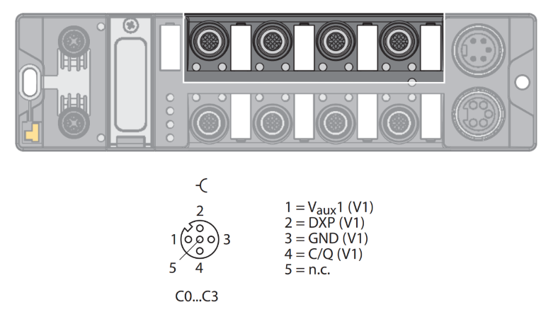
- The IO-Link ports of connectors C0 to C3 are class A ports.
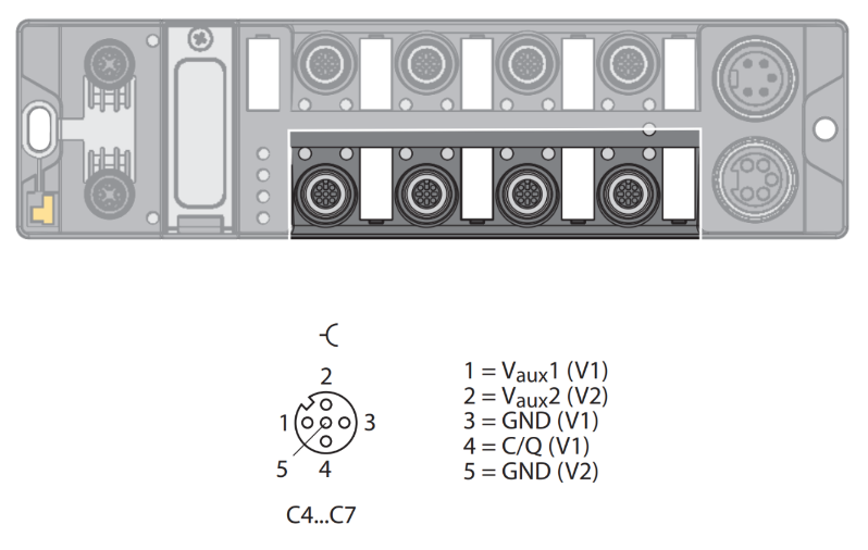
- The IO-Link ports on connectors C4 to C7 are class B ports.
In addition to the eight IO-Link channels, four universal digital DXP channels (PNP) are available; the four IO-Link channels are independently parameterizable and can operate in IO-Link mode or SIO mode (DI).
TURCK’s multi-protocol devices can operate on PROFINET, EtherNet/IP, and Modbus TCP with automatic protocol detection.
Operating principle
IO-Link Master TBEN-L… -8IOL enables IO-Link sensors and actuators to be connected to higher-level control systems. The device features fieldbus-independent I/O electronics with an Ethernet interface and IO-Link master functionality (Class A and Class B ports).
Via the Ethernet interface, the IO-Link master is connected to the Ethernet network as an EtherNet/IP device, Modbus TCP slave, or PROFINET device.
While the device is operating, process data is exchanged between Ethernet and IO-Link.
Multiprotocol technology
TBEN-L4-8IOL4 can be used with the following three Ethernet protocols
- Modbus TCP
- EtherNet/IP
- PROFINET
The Ethernet protocol required for the device can be auto-detected or determined manually.
Automatic protocol detection
A multi-protocol device can operate on all EtherNet/IP devices, Modbus TCP slaves, or PROFINET devices without user intervention. After the device-o-protocol is detected, access to the device from other protocols is read-only.
Manual Protocol Selection
Users can also define protocols manually. In this case, the device is locked to the selected protocol. For other protocols, devices can only be accessed on a read-only basis.
Simple IO-Link Device Integration (SIDI)
TURCK’s Simple IO-Link Device Integration (SIDI) simplifies the handling of IO-Link devices in PROFINET engineering systems, with devices already integrated into the master GSDML file.
The user can select a device from the software that builds the Profinet IO Controller (e.g., Siemens’ TIA) and integrate it into the project using the drop-down field as if the device were a sub-module of a modular I/O system.
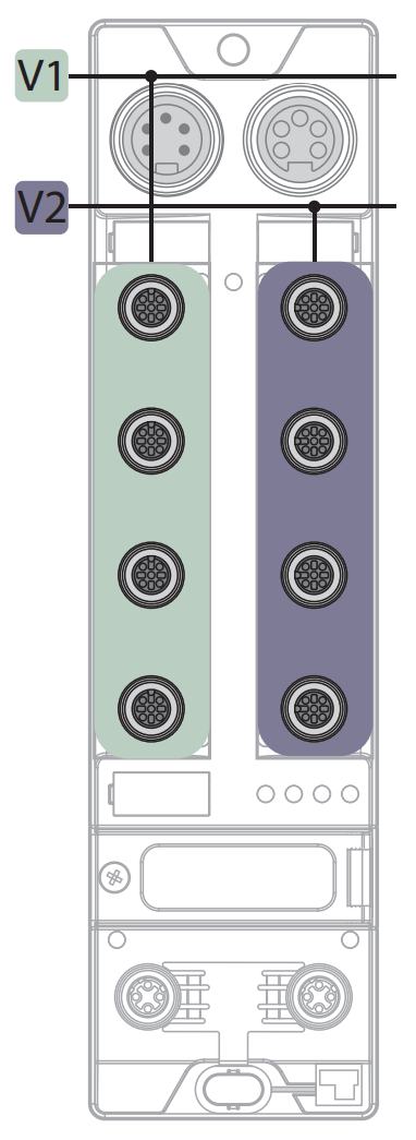
Supply concept
The TBEN-L4-8IOL4 is supplied via two independent voltages V1 and V2.
- V1 = supply of module and each slot
- V2 = supply for module and each connector (individually removable)
I/O channels are divided into different potential groups, “removable I/O” (supplied through V2) and “non-removable” I/O (supplied through V1), allowing for safe shutdown of a piece of equipment via an emergency stop circuit.
Class A
Class B
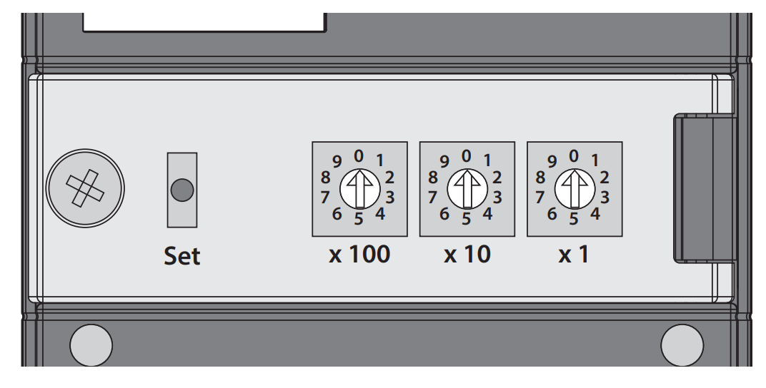
Setting the IP address
The IP address of the TBEN-L4-8IOL4 can be configured via the three 1 rotary coding switches or the Web server Turck Service Tool.
Ethernet/IP
This is the Ethernet/IP specification for TBEN-L4-8IOL4.
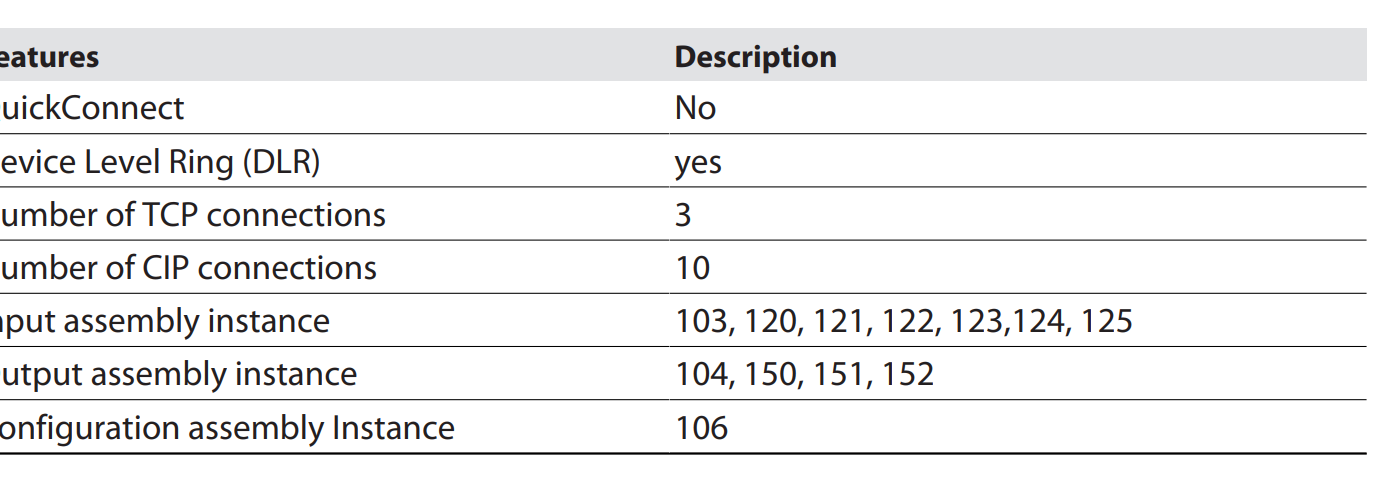
Input/Output Assembly
Here is the Assembly list for TBEN-L4-8IOL4 Ethernet/IP.
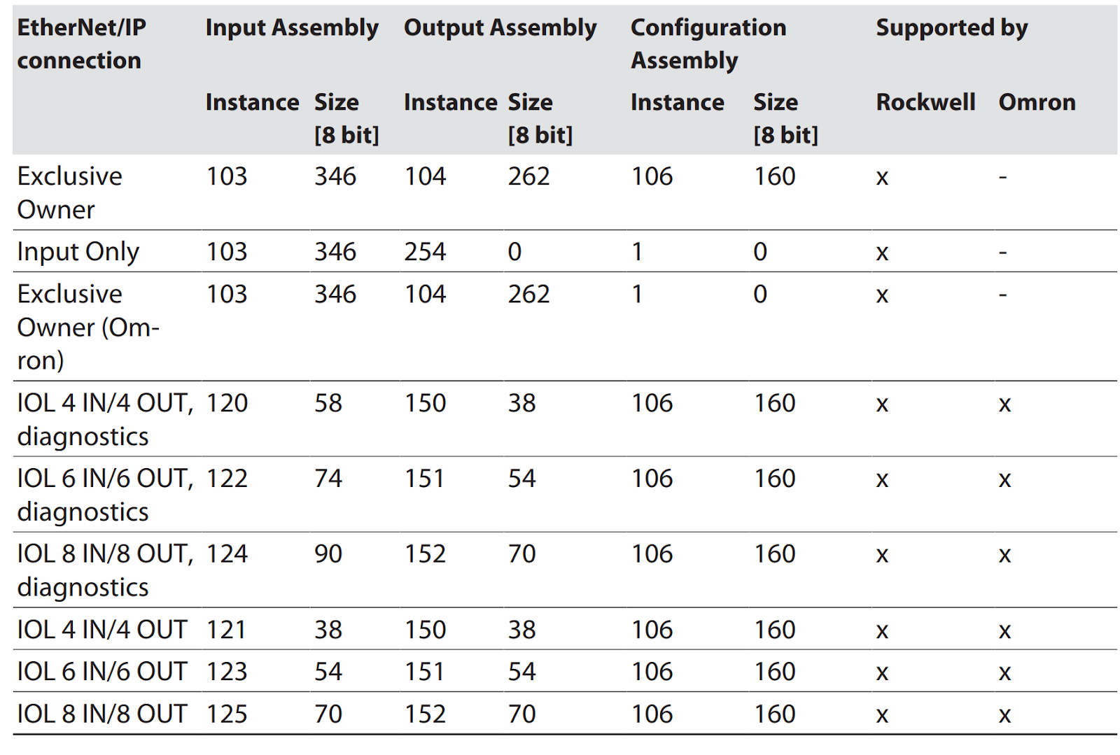
103
This is the Input Assembly for TBEN-L4-8IOL4 Ethernet/IP, Instane 103.
104
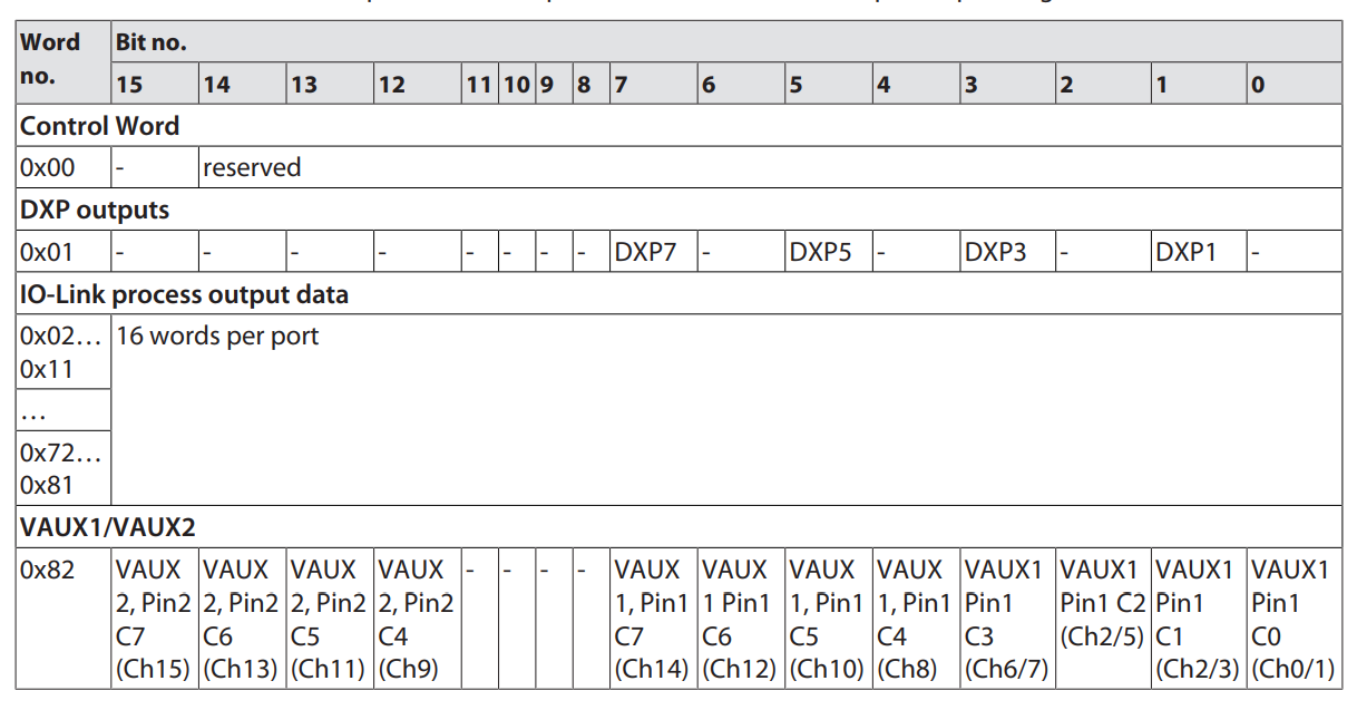
This is the Output Assembly for TBEN-L4-8IOL4 Ethernet/IP, Instane 104.
Implementation
Turck Side
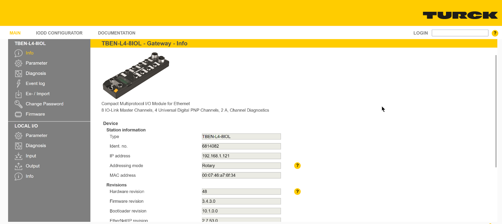
Start from the TURCK side first: enter the IP address of TURC from Chorme or Firefox.
こちらはTURCKのWeb serverになります。
password
The Default Password for the TURCK device is password.

Decide whether you want to change the Default Password depending on your actual usage.

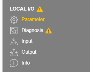
Error
If the TURCK module encounters an error, LOCAL>Diagnosis! with a yellow mark.
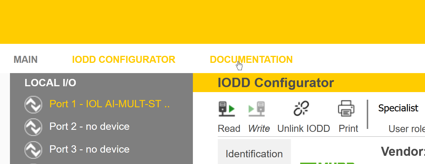
Port Configuration
Next, click LOCAL I/O>Parameter to configure each port of the TURCK IO-Link Master.
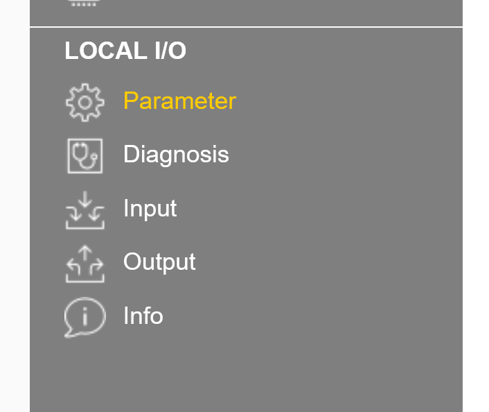
The settings screen for each port will be displayed.
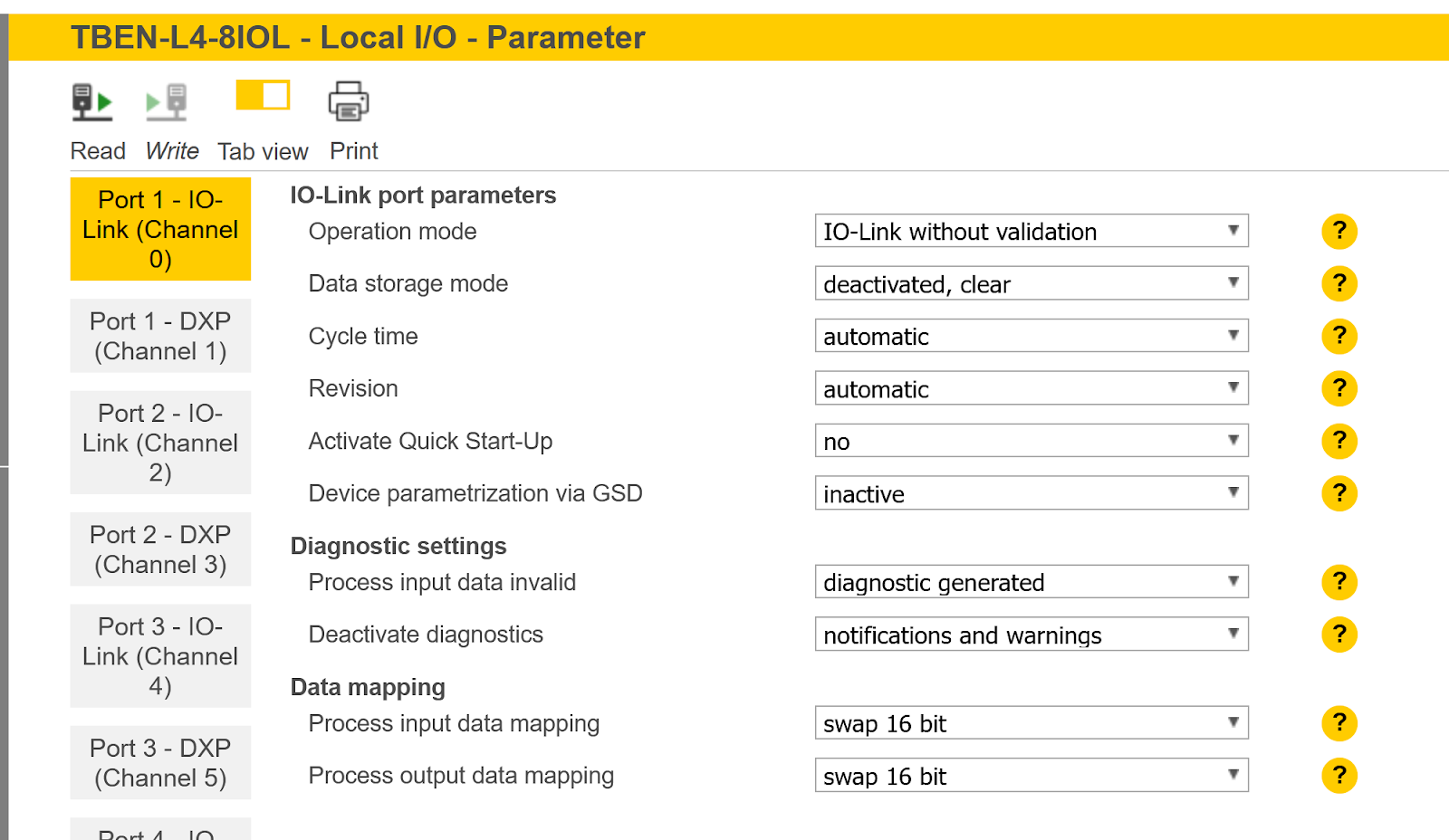
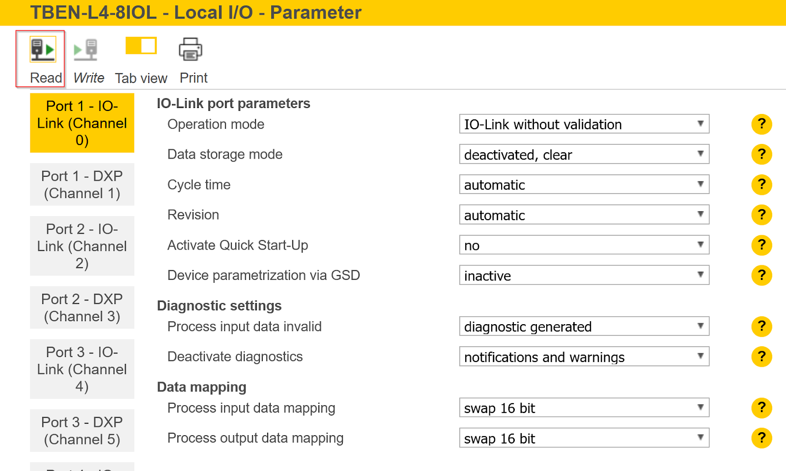
Click the Read button to read the current IO-Link Port settings.
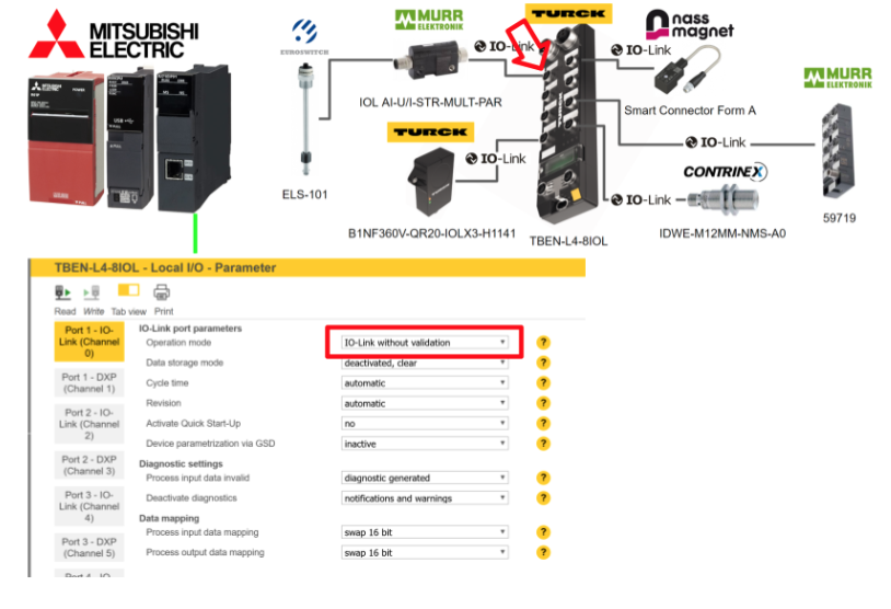
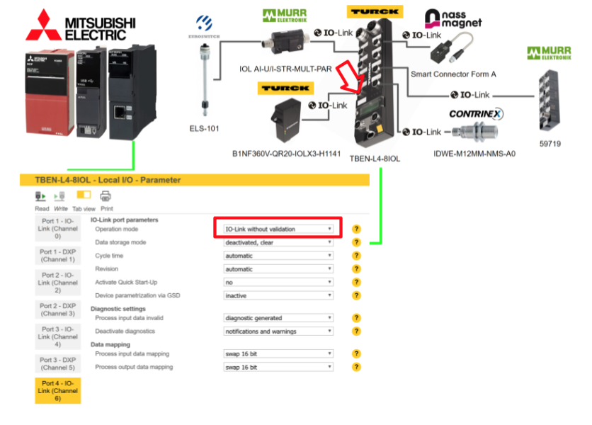
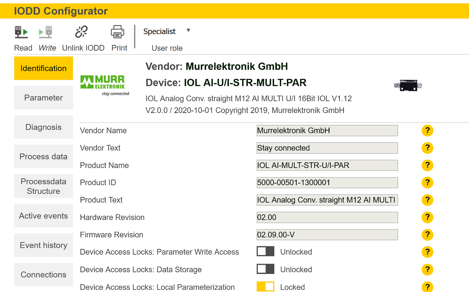
Port1
Port 1 is connected to Murr’s analog to IOLINK converter, so IO-Link without validation is selected for Operation Mode.
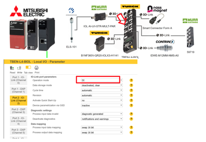
Port2
Port 2 is not connected to anything, so DI is selected for Operation Mode.
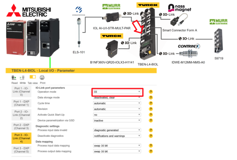
Port3
Port 3 is not connected to anything, so DI is selected for Operation Mode.
Port4
Port 4 is connected to the B1NF360V-QR20-IOLX3-H1141 IOLINK device that detects the tilt of the TURCK, so select IO-Link without validation for Operation Mode.
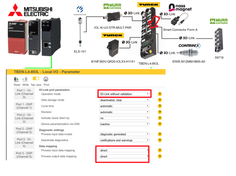
Port5
Port 5 is connected to Nass magnet’s Smart Connector Form A IOLINK device, so select IO-Link without validation for Operation Mode.

Port6
Port 6 is not connected to anything, so DI is selected for Operation Mode.

Port7
Port 7 is connected to Murr’s IOLINK Hub 59719, so IO-Link without validation is selected for Operation Mode.
Port8
Port 8 is connected to the CONTRINEX Smart Sensor IDWE-M12MM-NMS-A0 IOLINK device, so select IO-Link without validation as the Operation Mode.

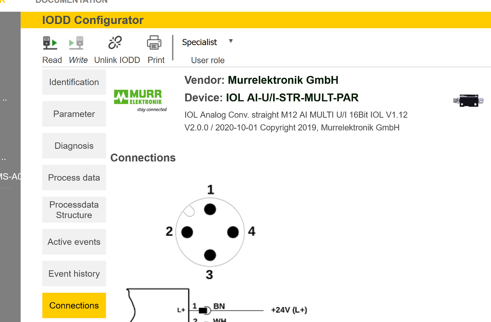
IODD Configurator
Next, we introduce TURCK’s IODD CONFIGURATOR. This tool allows you to set parameters and check diagnostic information for each port’s IO-LINK device.

例えばPort1を設定してみましょう。
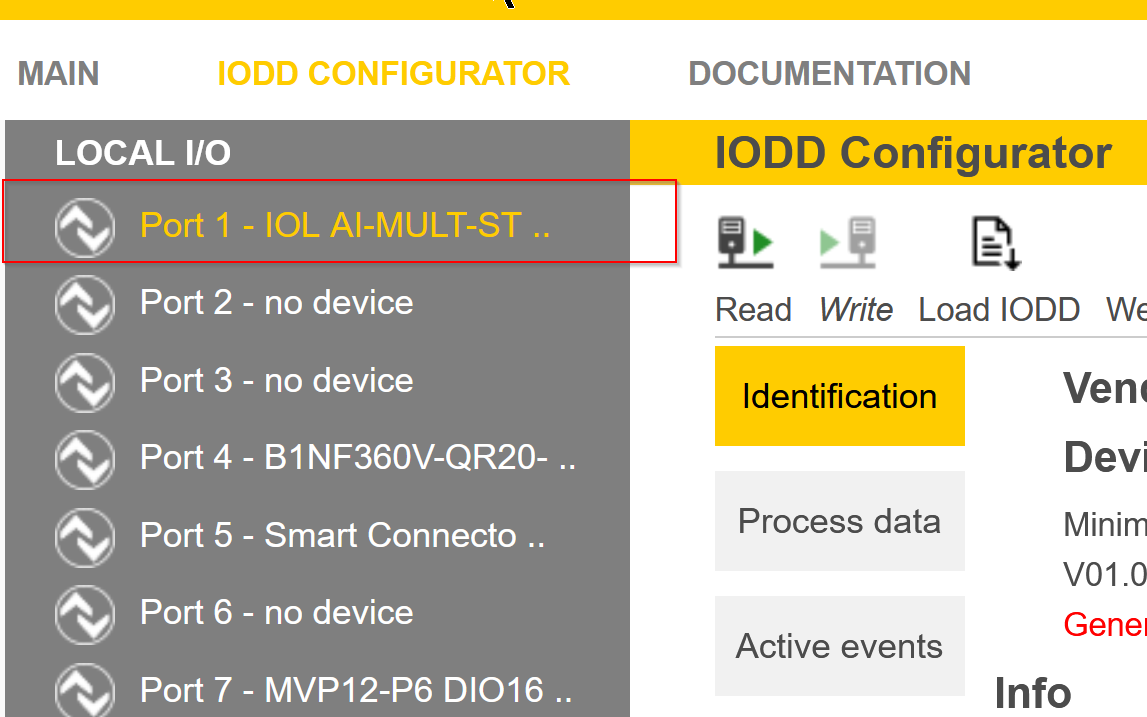
Load IODD File
If the PC you are working on is connected to the Internet, you can click on the “Web search” button to search directly for IODDs and download the IODD File.
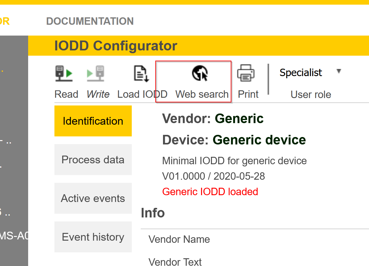
Done!
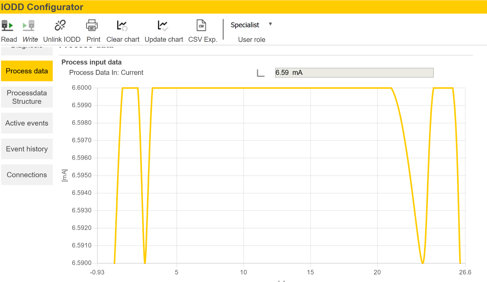
Process data
In the Process data section, you can check the input/output data of the relevant IO-Link device.You can also click on the small Trend button next to Process data.
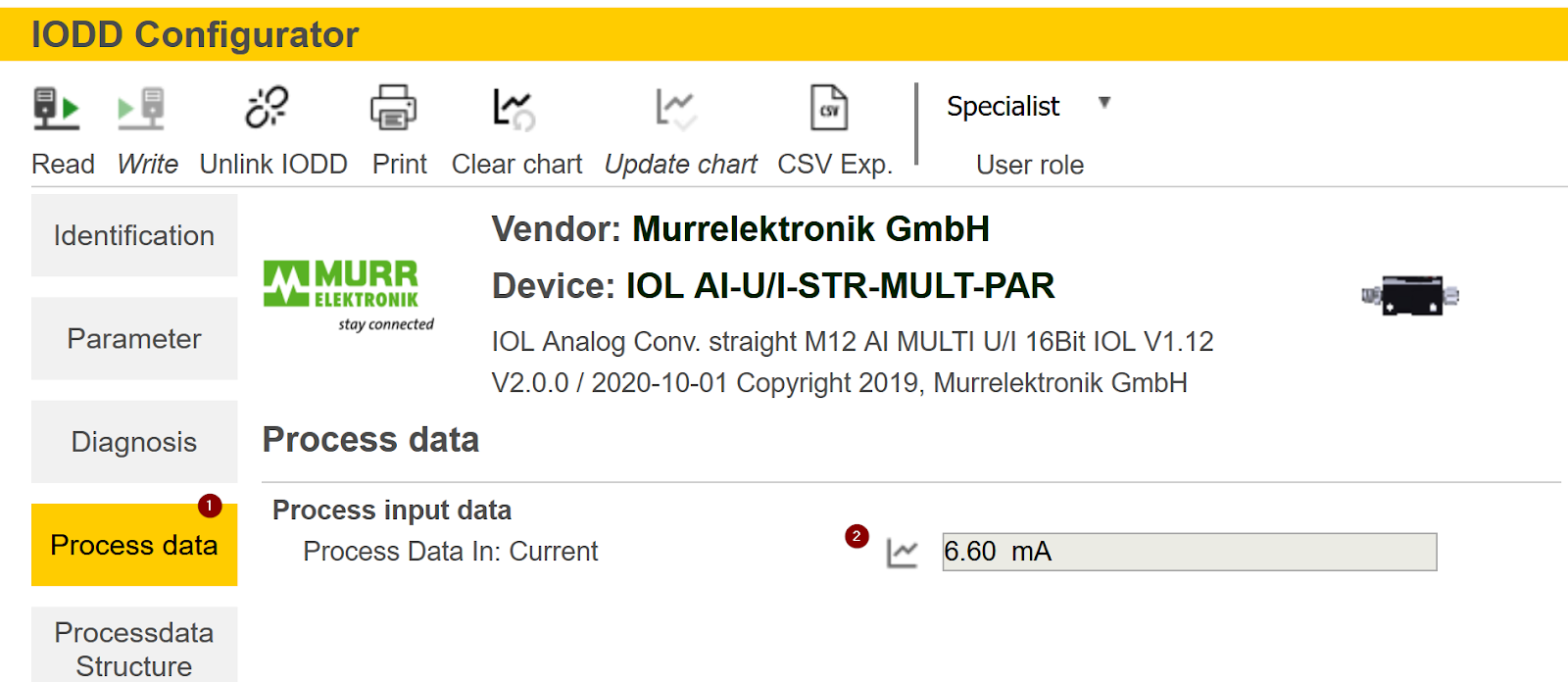
A graphical table of Porcess Data can be displayed.
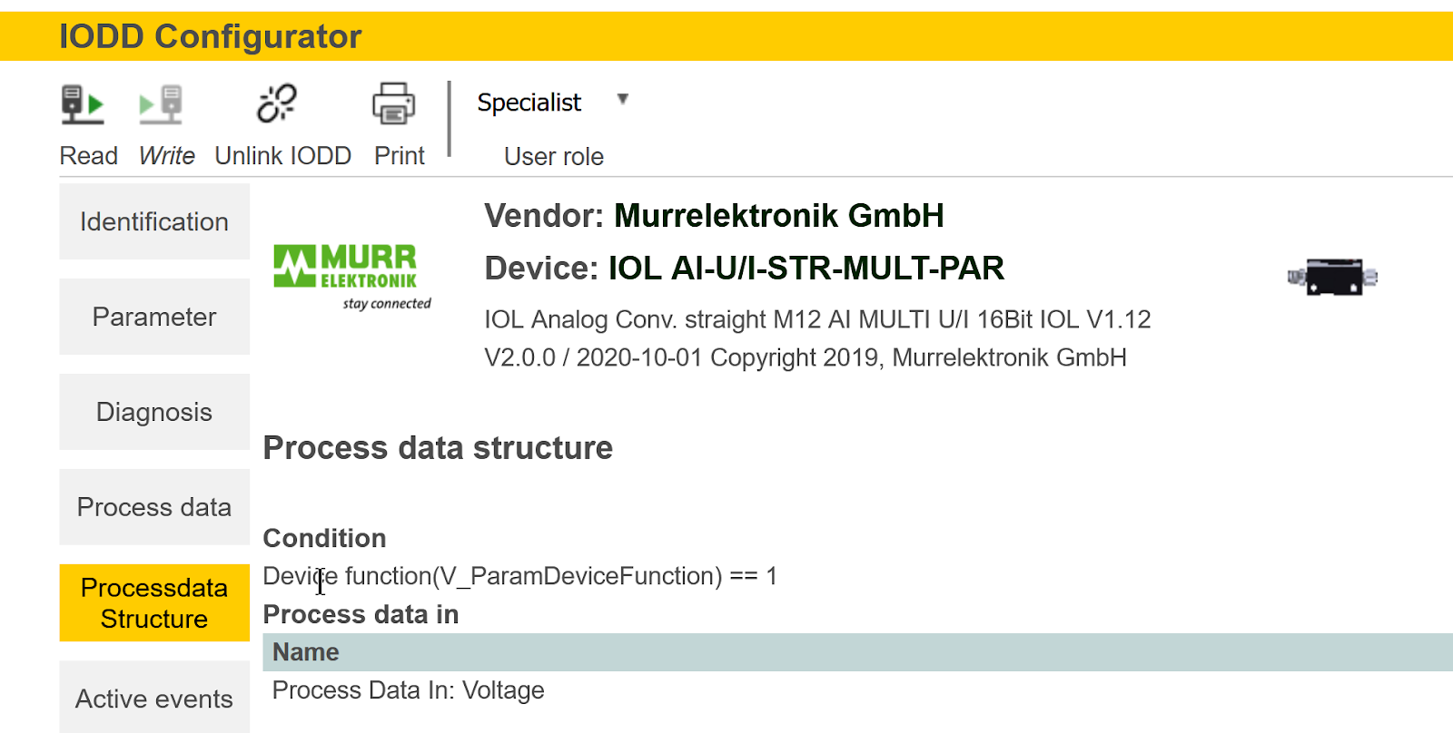
Process data Structure
The Processdata Structure section allows you to check the process data structure of the relevant IO-Link device. This feature is very useful for debugging and programming.
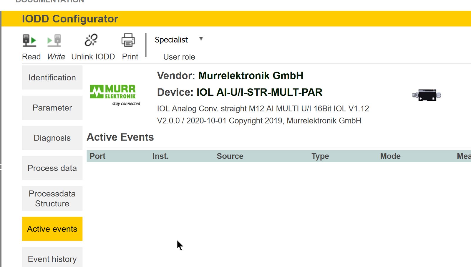
Active events
In the Active events section, you can check the alarms that are occurring for the corresponding IO-Link device.
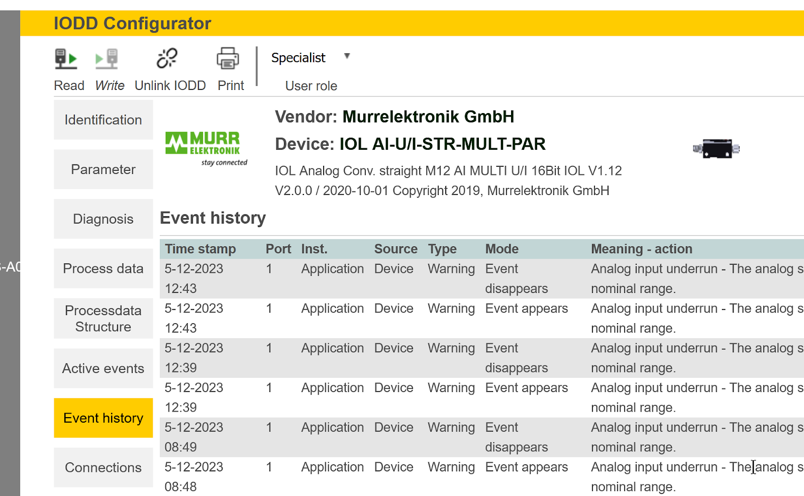
Event history
In the “Event history” section, you can check the Amler history of the relevant IO-Link device.
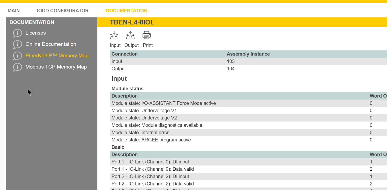
Documents
The DOCUMENTS function allows you to check detailed information about the device you are currently using.
For example, since we will be using Etherent/IP, the “Ethernet/IP Memory Map” item allows us to check the area used by Etherent/IP.
Mitsubishi Side
The next step is to prepare the IQ-R side of Mitsubishi.
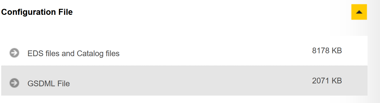
Download EDS File
Download the EDS File of TURCK with the following LINK.
https://www.turck.de/en/product/6814082
Install Ethernet/IP Configuration Tools
To build an Ethernet/IP network with the RJ71EIP91, please download the Configuration Tools at the link below and install it on your PC.
New Project
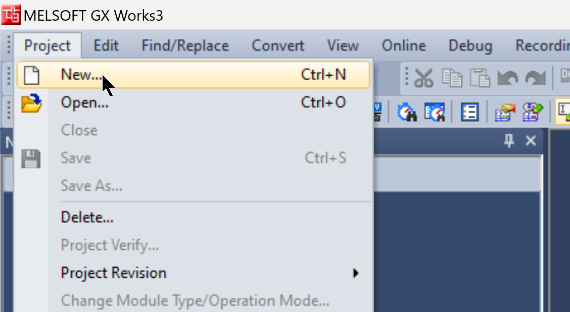
Start GXWORKS3 and add a new project by going to Project>New.
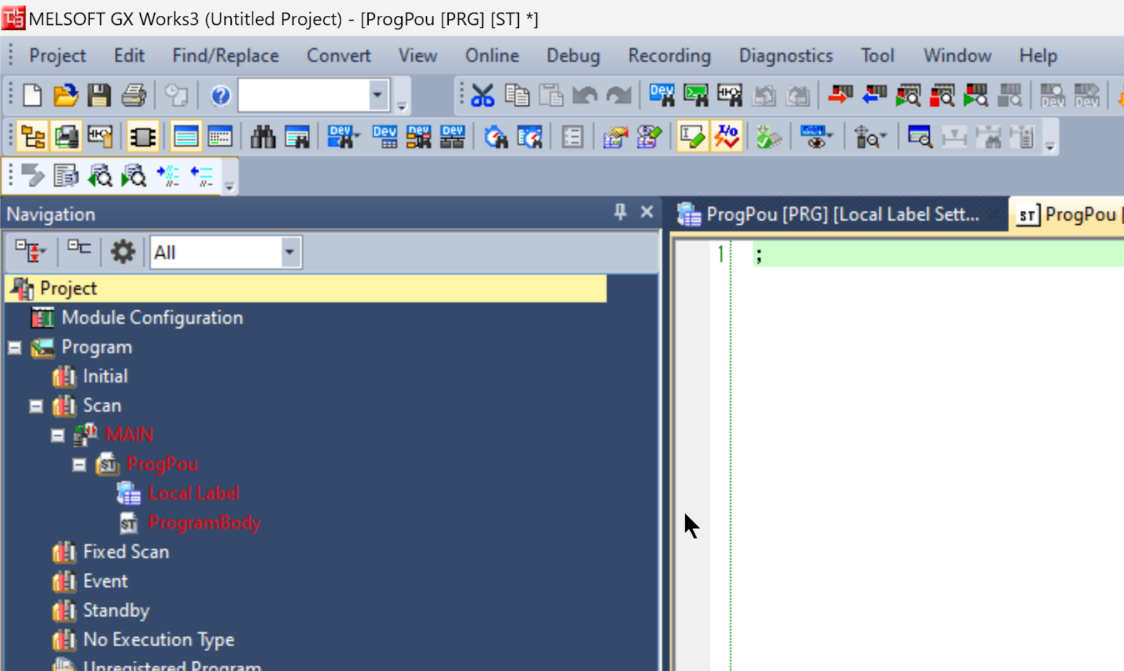
Since the R00 CPU will be used this time, set Type to R00 and Program Language to ST.
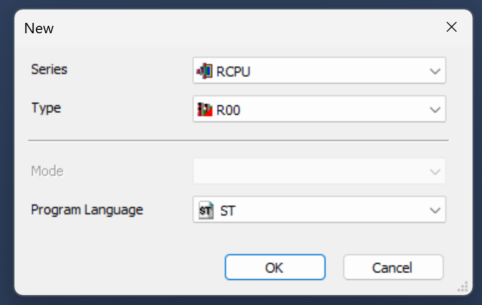
Done!
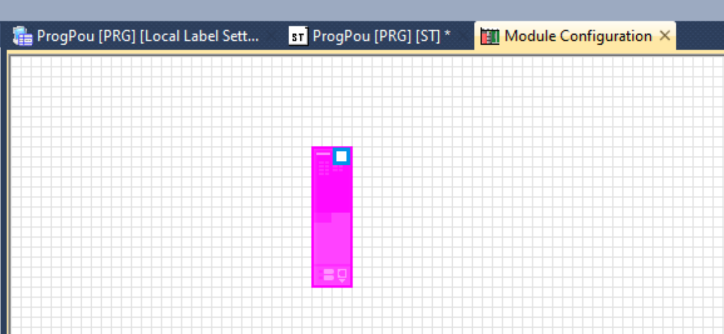
Module Configuration
Click on “Module Configuration” to change the Hardware Configuration.
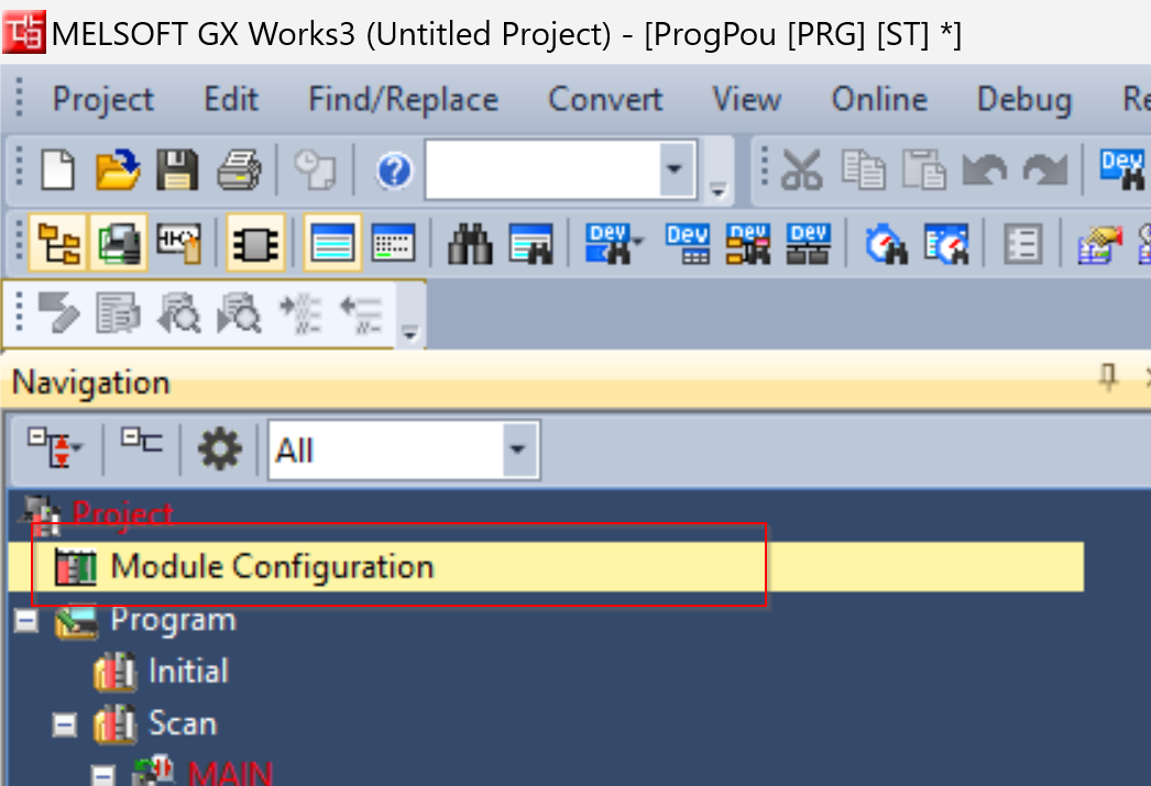
This is the Module Configuration screen.
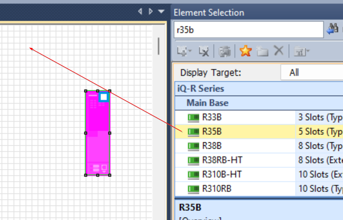
R35B
Add Power Rack R35B.
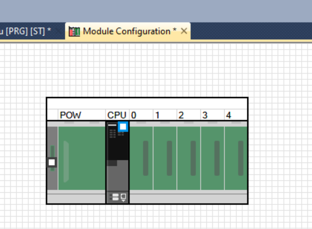
R00 CPU should be pulled into the “CPU” slot.
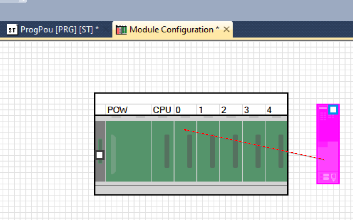
Done!
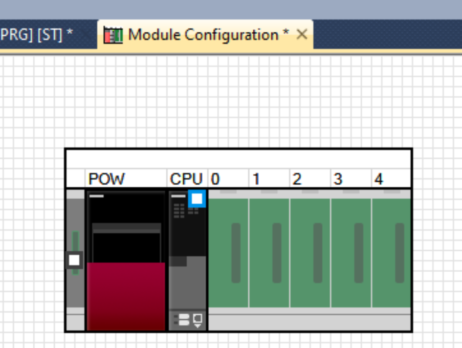
R61P
Add power module R61P to the POW Slot.
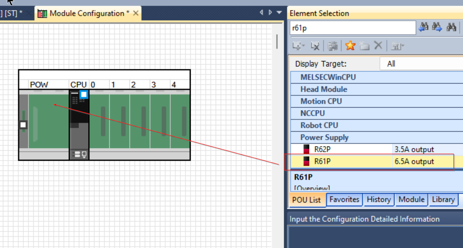
Done!
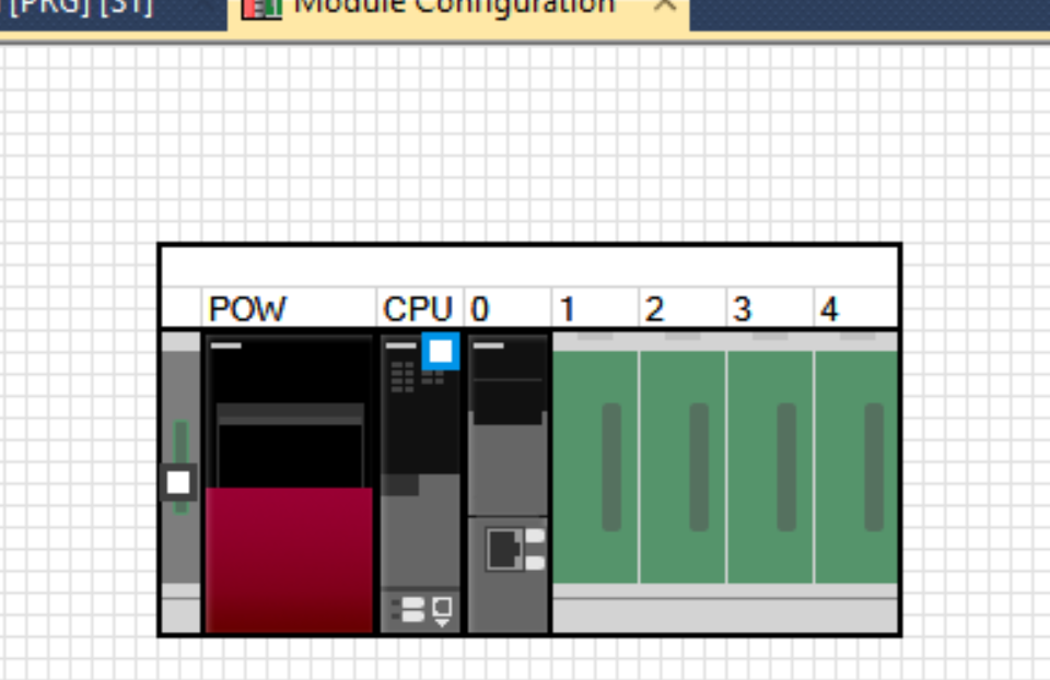
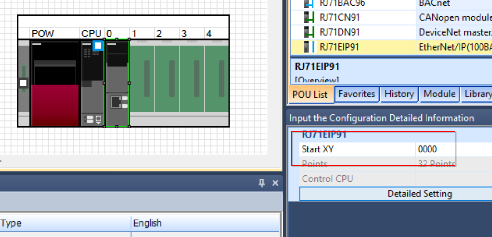
RJ71EIP91
The last step is to add the RJ71EIP91 module to Slot0.
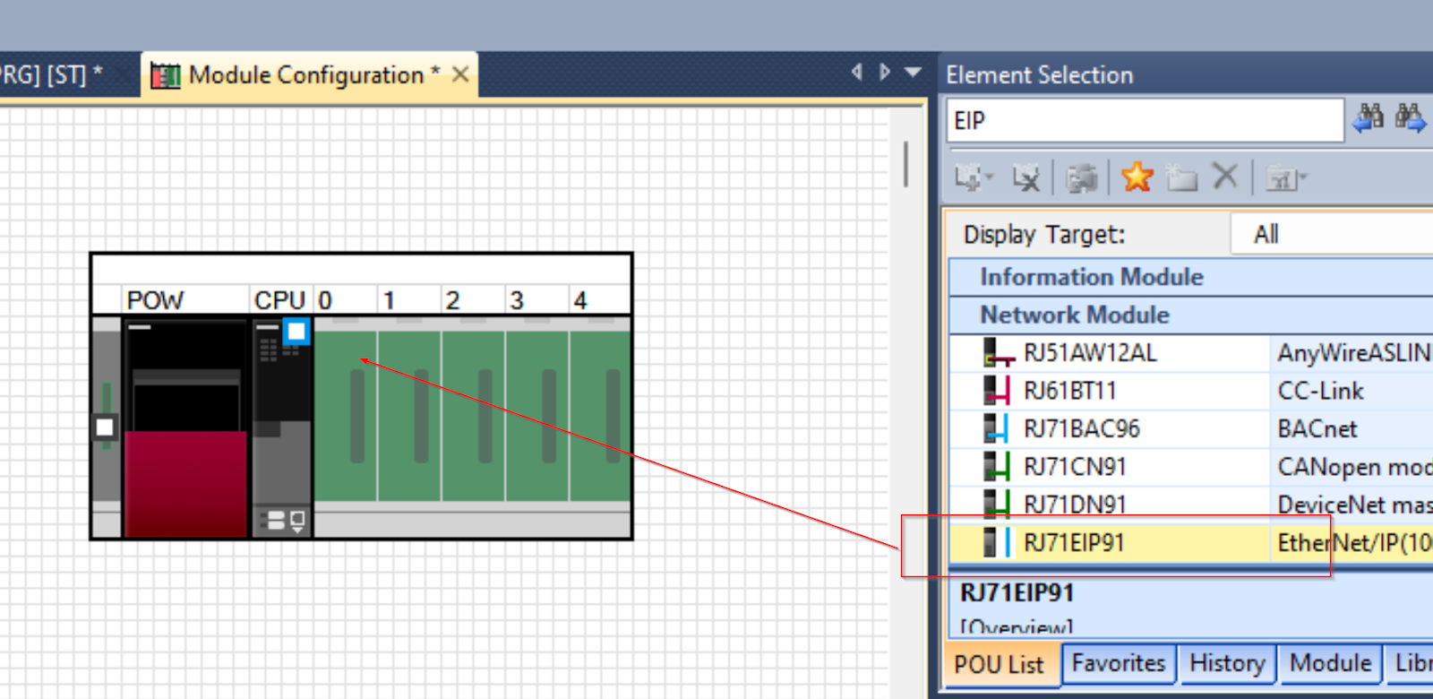
Done!
If you select RJ71EIP91, Start XY will control the module and check its status. Since this Tutorial will be a label program, you do not need to worry about that StartXY.
Add Label
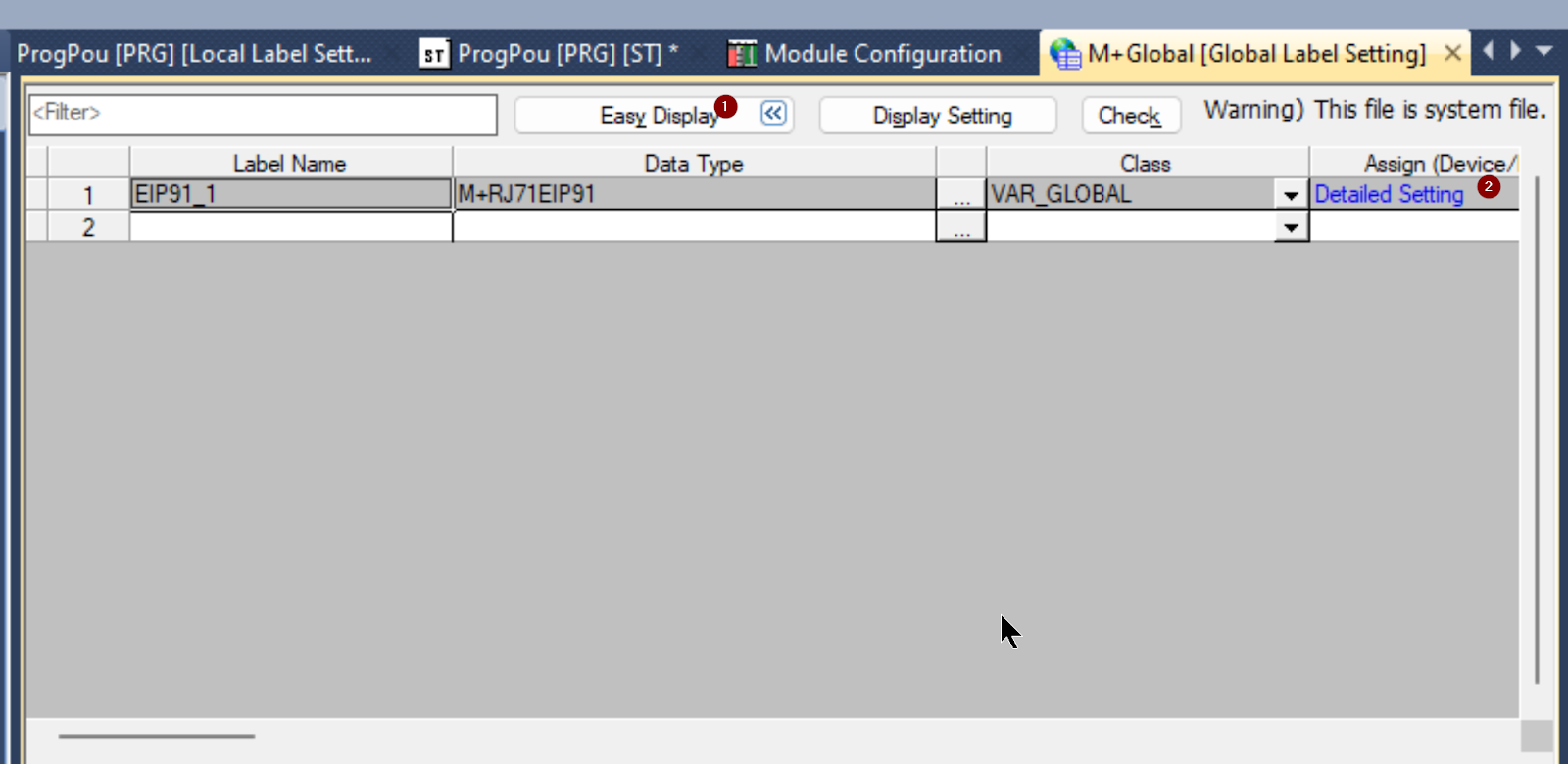
Right click on Elements Selection>Module>RJ71EIP91>Add Module Label to add the Global Label of the EIP module to the project.
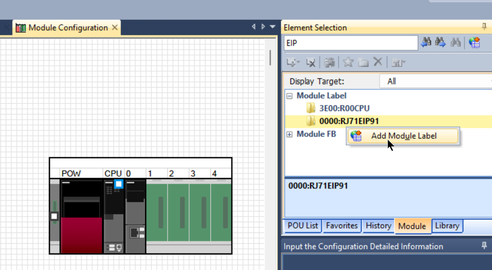
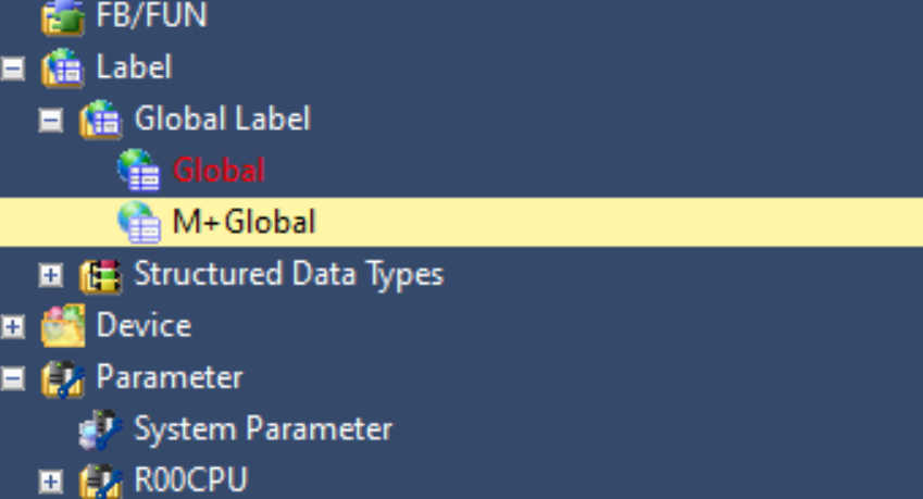
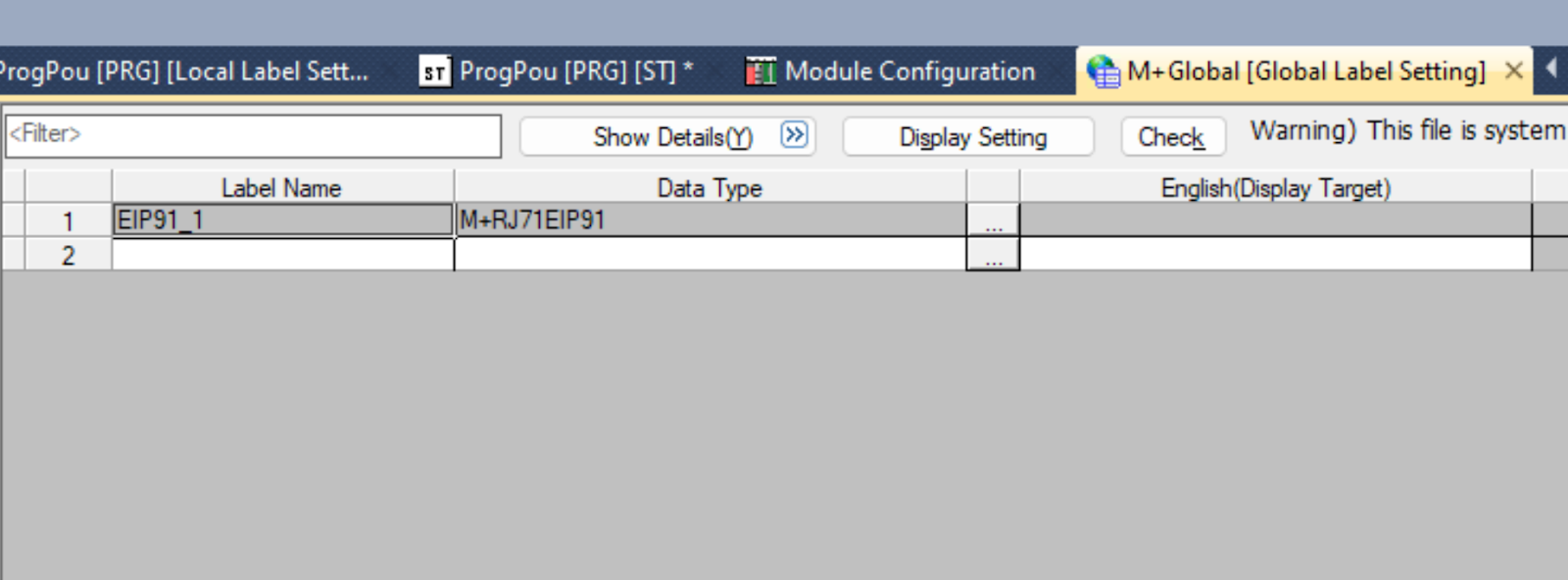
A Global label List called M+Global has been added.
EIP91_1 is defined, because it will be used later when Mitsubishi’s RJ71EIP91 Function Block is used.
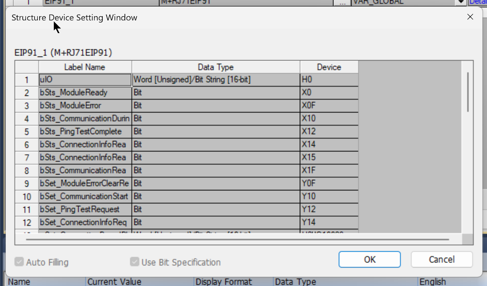
Click on “Detail Display” to display the “Assign” section, which has a blue “Detailed Setting”.
GXWORKS3 also defines the XY and Buffer Memory required for RJ71EIP91.
CPU IP Address
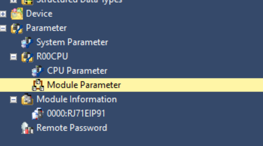
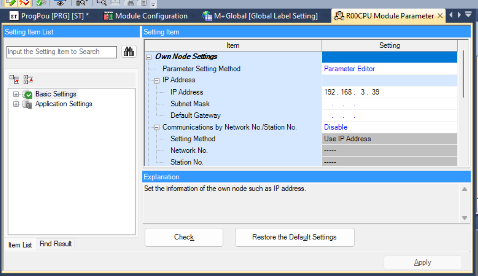
Click on Parameter>R00CPU>Module Parameter to set the IP address of the PLC.
Match the IP Address to the application.
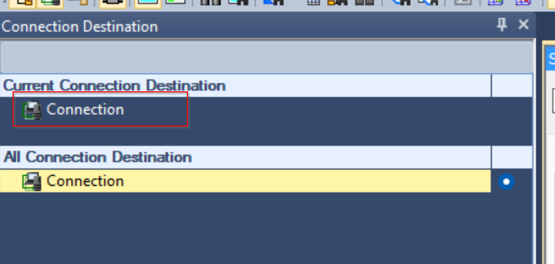
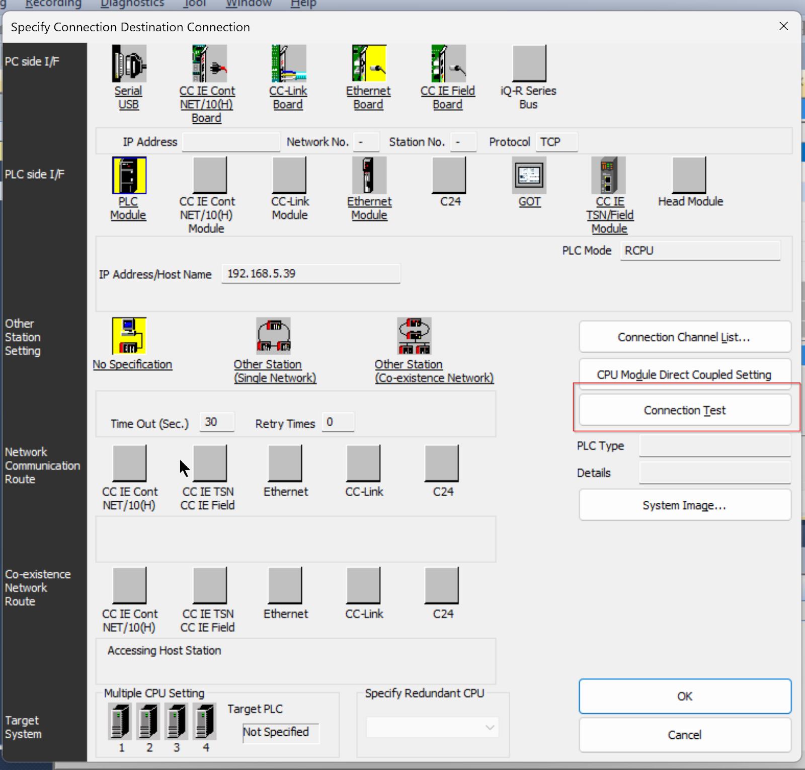
Connection Destination can be set to communicate with the CPU of the actual device.
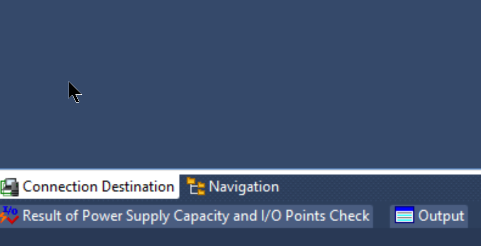
Click on the Conenction setting you are currently using.
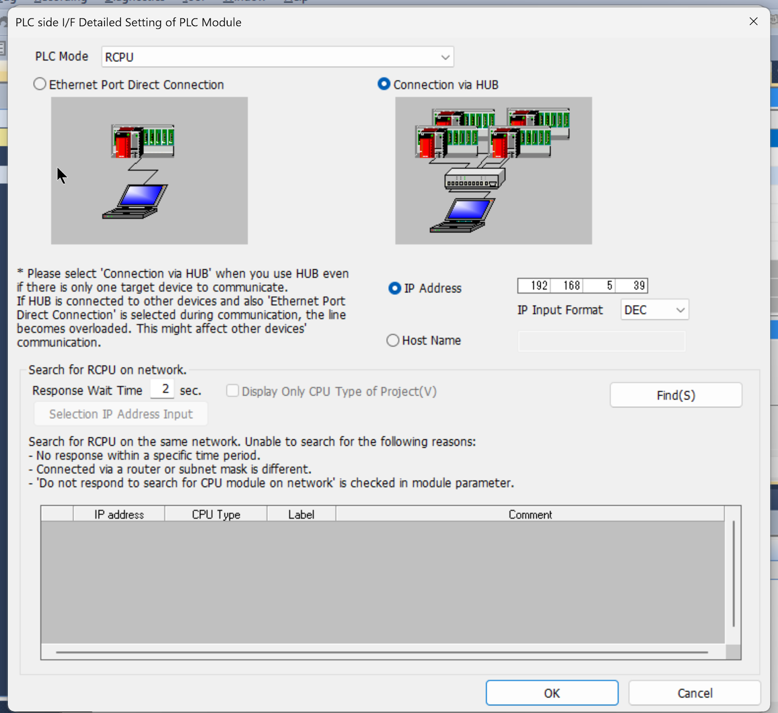
Click PLC Module to configure communication settings.
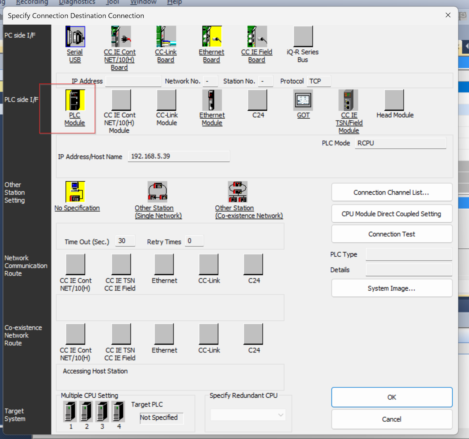
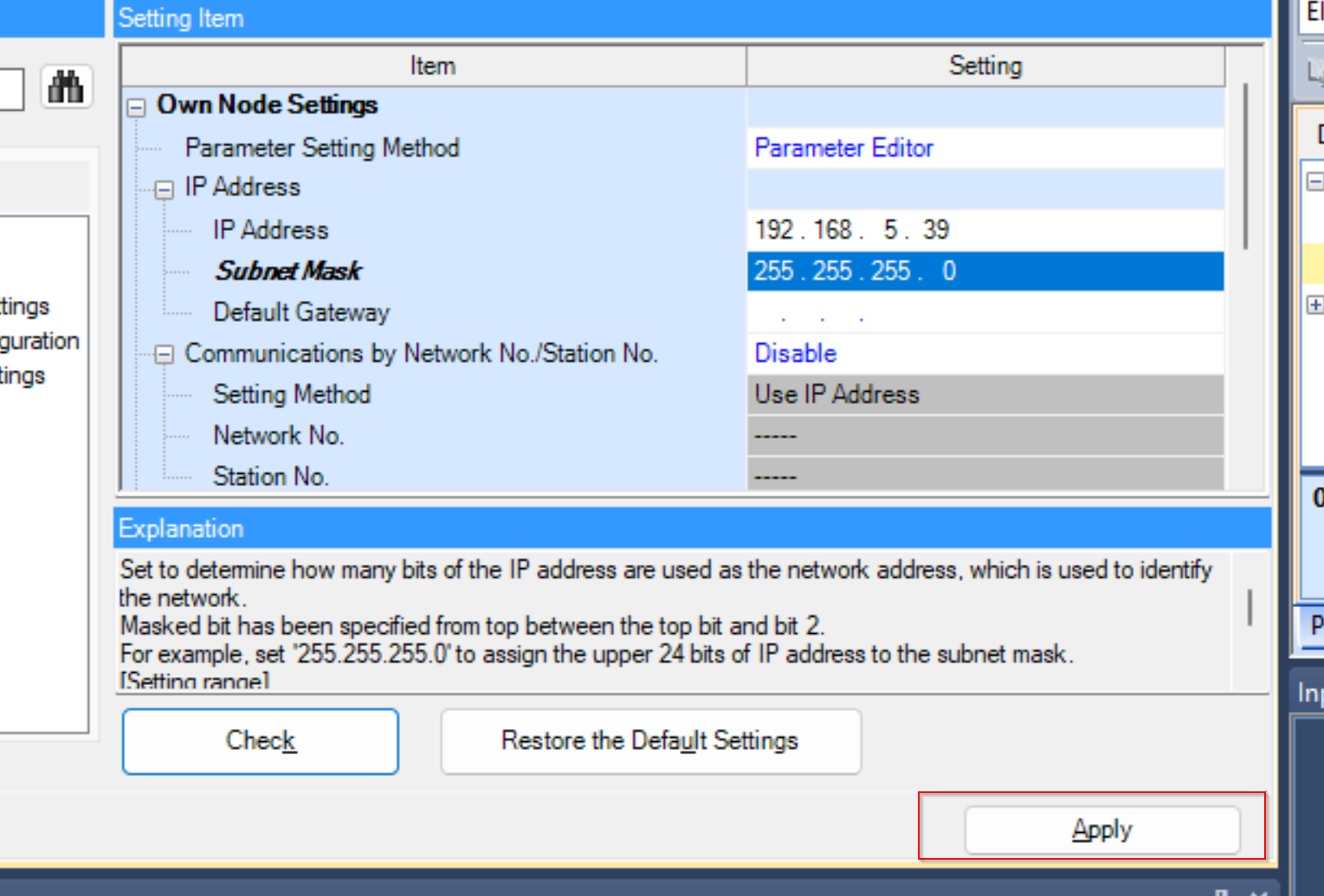
Now it is 192.168.5.39.
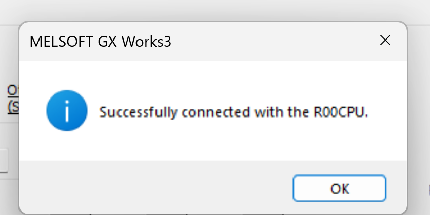
Click the Connection Test button to test communication.
Done!
Set the IP address and check for configuration errors with the Check button.
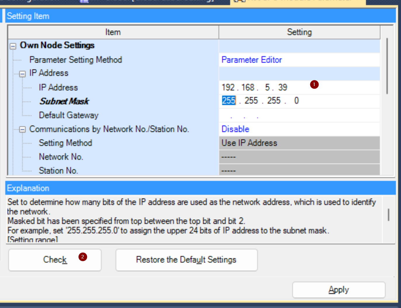
Done!
The Apply button saves the settings.
RJ71EIP91 Configurations
The next step is to configure the RJ71EIP91.
IP address
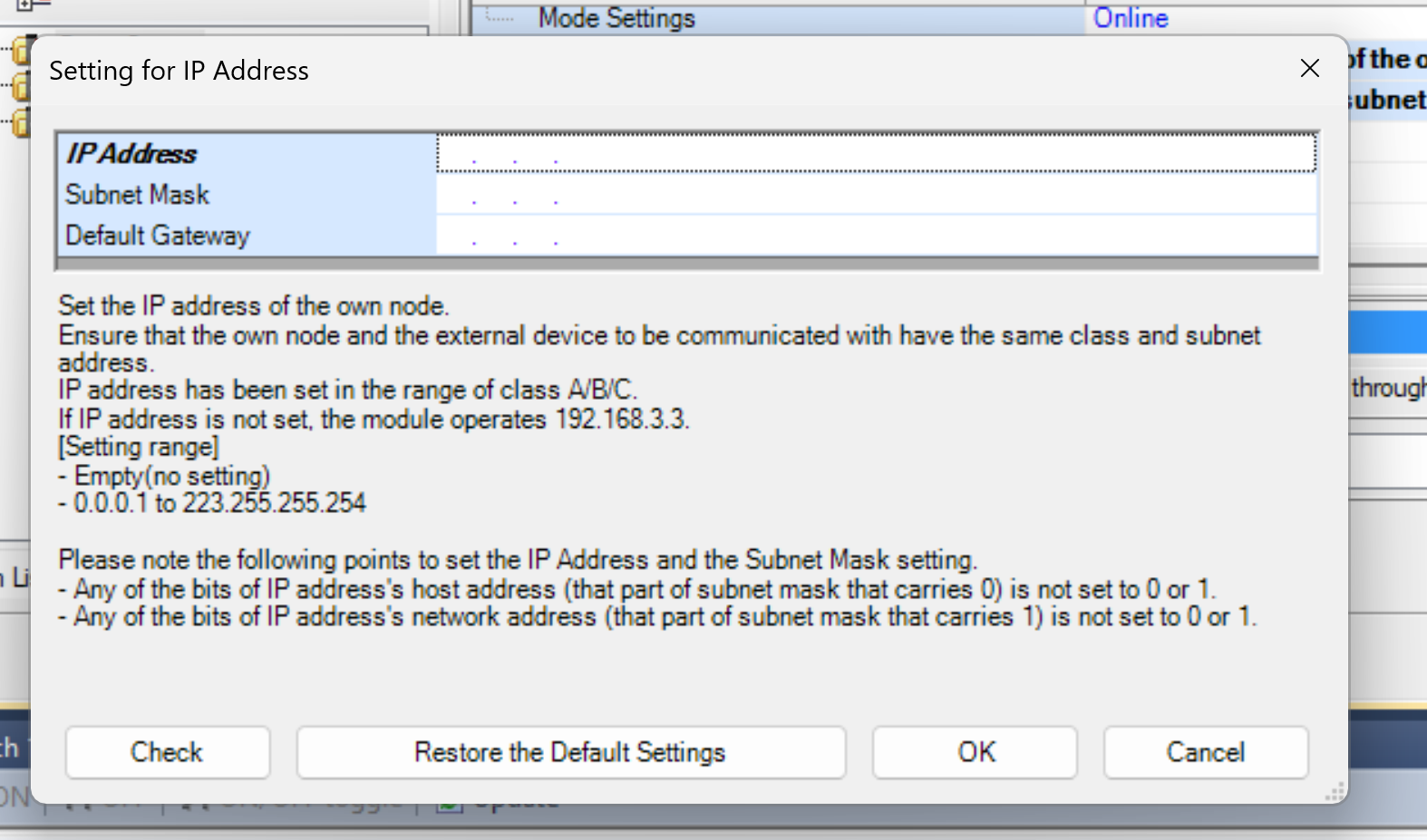
Click Module Information>0000:RJ71EIP91 to set the IP address of RJ71EIP91.
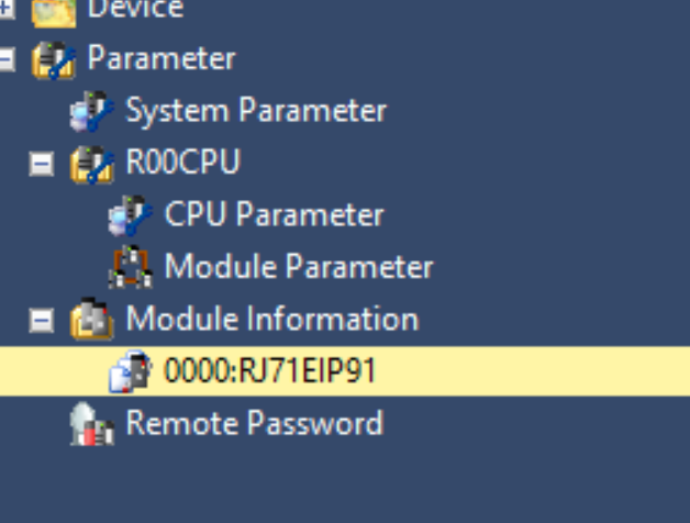
Double-click the IP Address field.
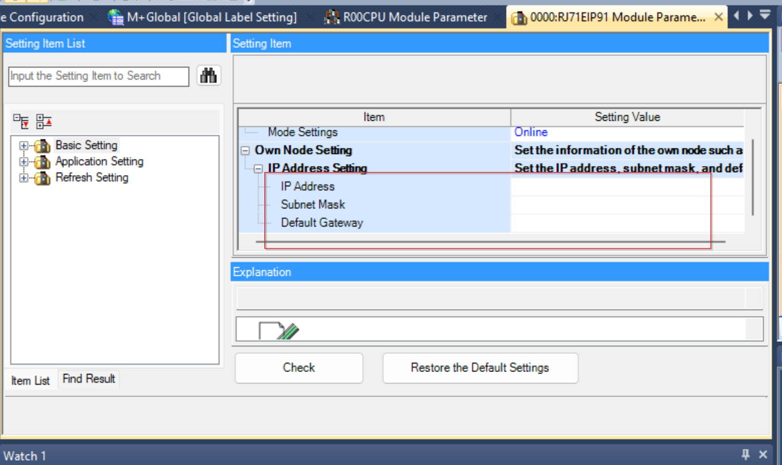
Set IP Address and Subnet Mask according to your application.
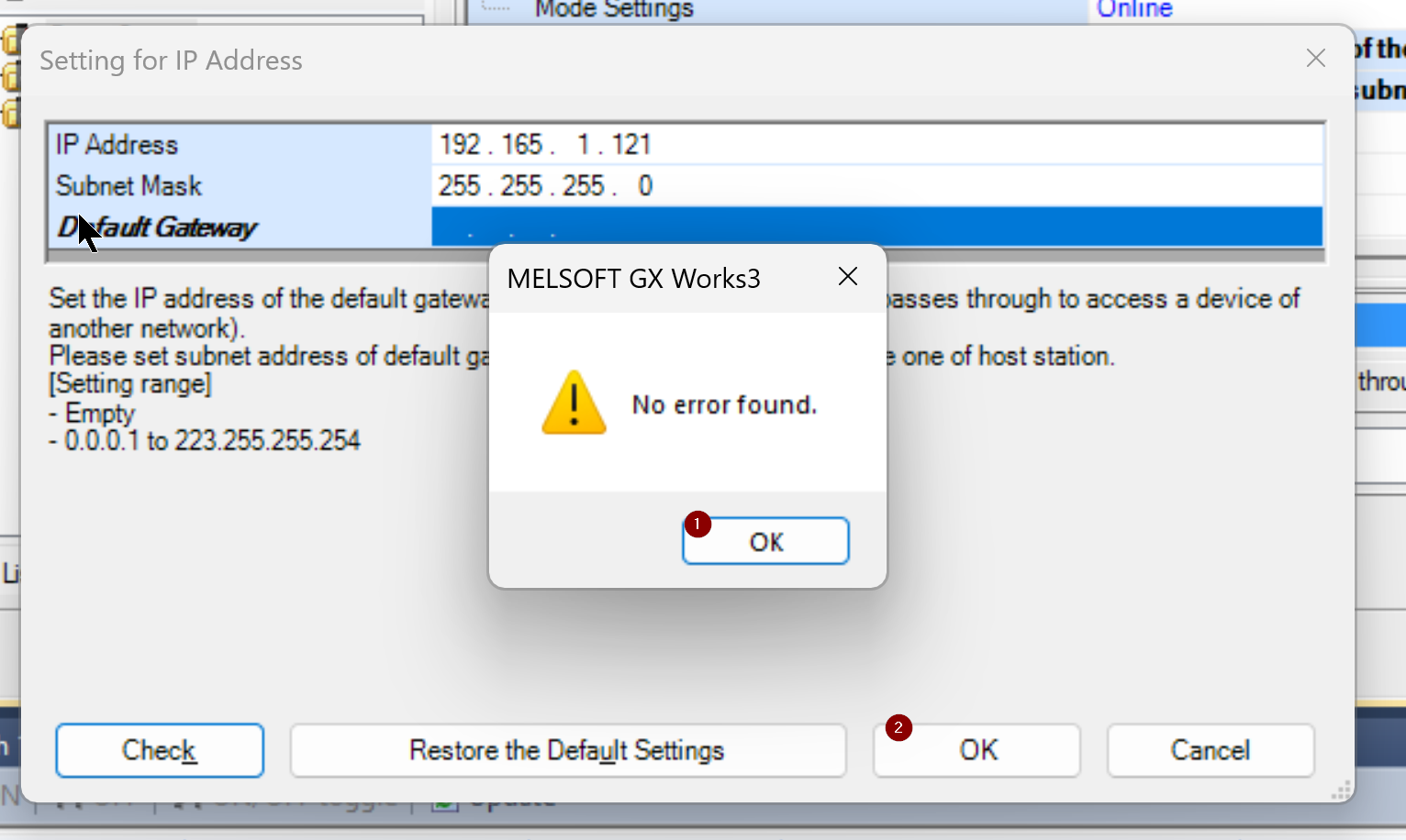
After setting the IP address, confirm the settings with the Check button.
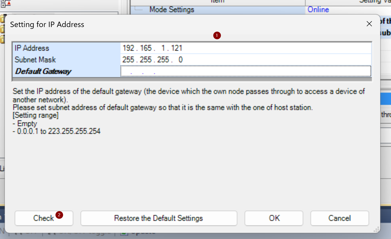
Done!
Configure the Ethernet/IP Network
Now that the basic configuration of the module is complete, the next step is to build an Ethernet/IP network.
Stat tools
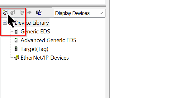
Double-click Ethernet/IP Configuration Tool to launch the tool.
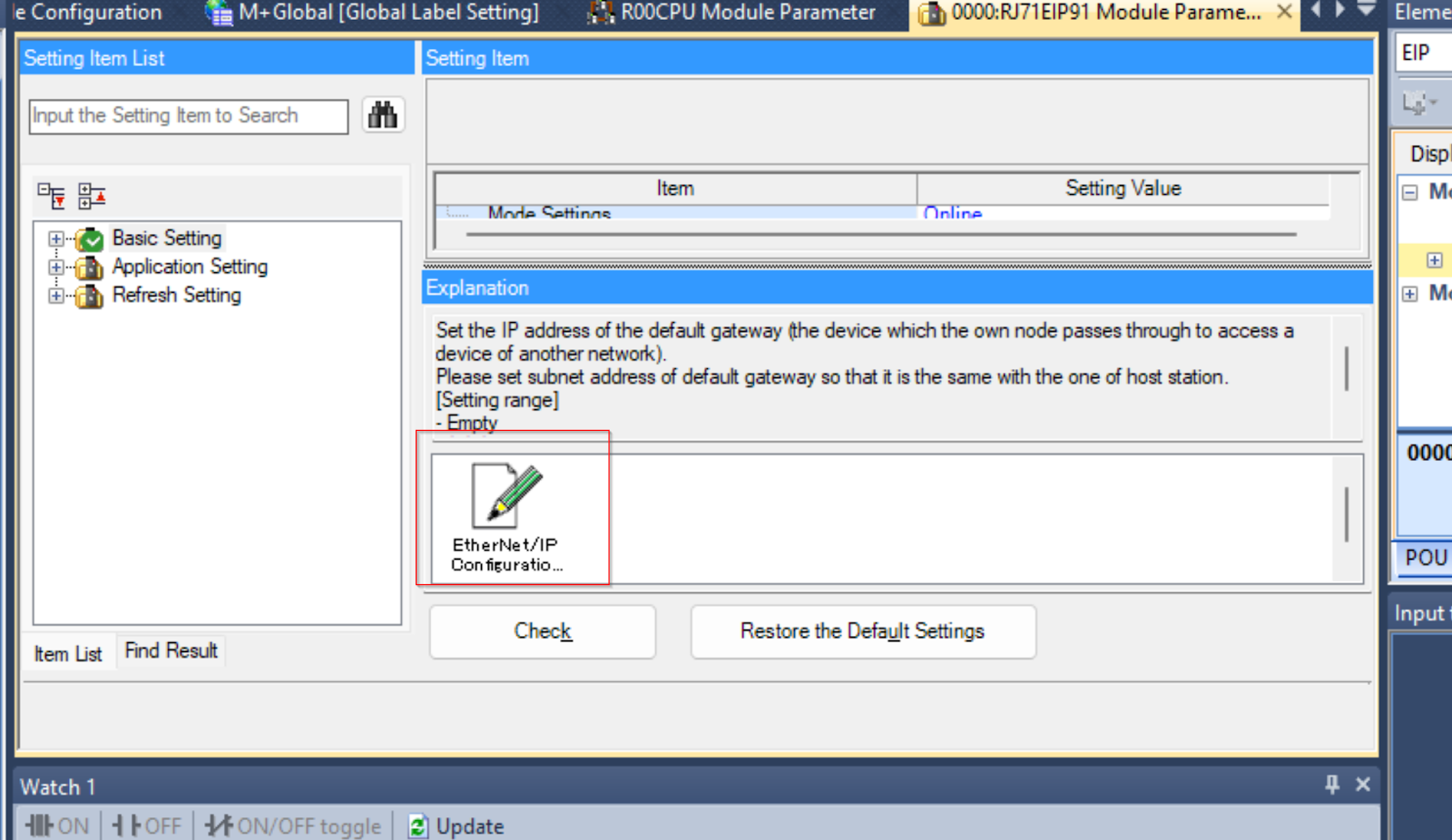
This is the Ethernet/IP Configuration Tool for the RJ71EIP91.
Install EDS File
Devie LibraryにTURCKのEDS Fileを追加します。
Proceed with Next.
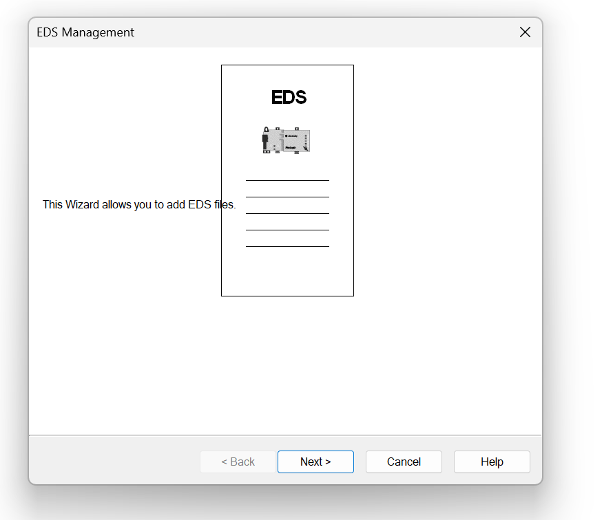
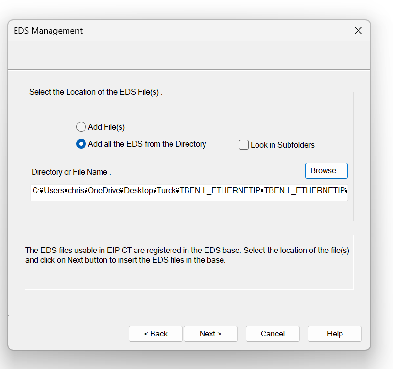
The screen will change to the Add EDS File screen.
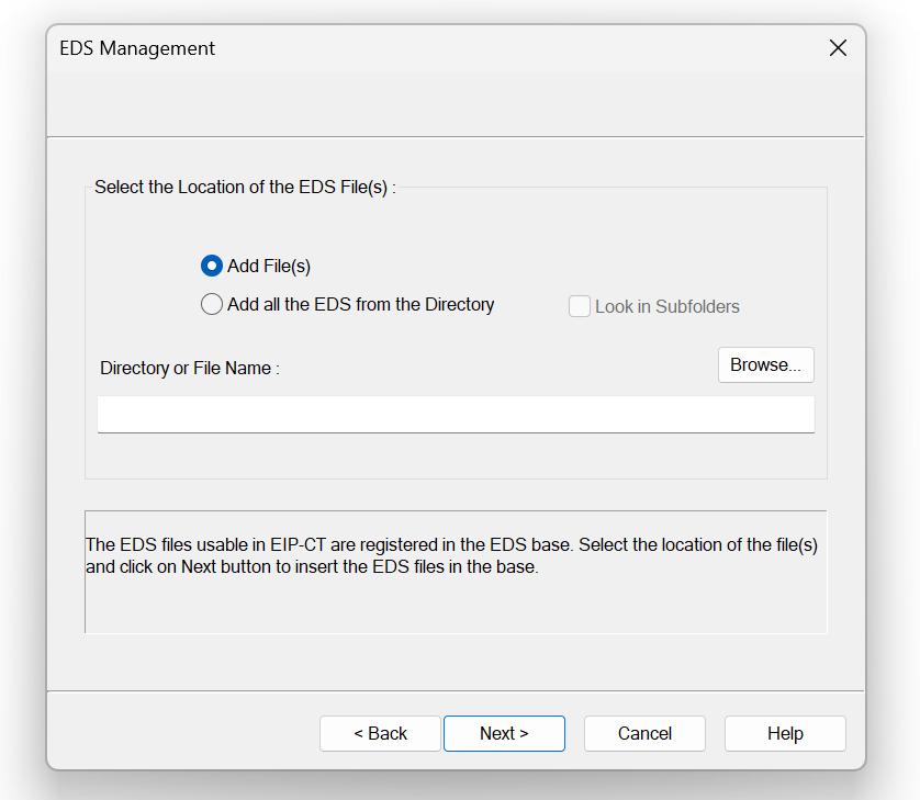
Select Add all the EDS from the Directory and click >Browse.
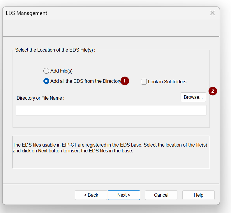
Set the Folder where the EDS File is stored and press Next> to proceed.
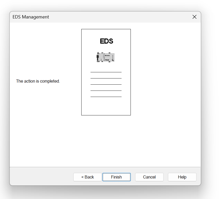
Proceed with Next>.
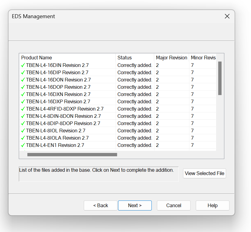
Done!
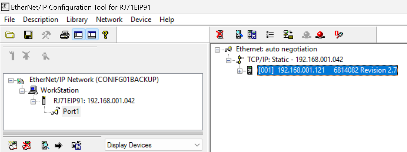
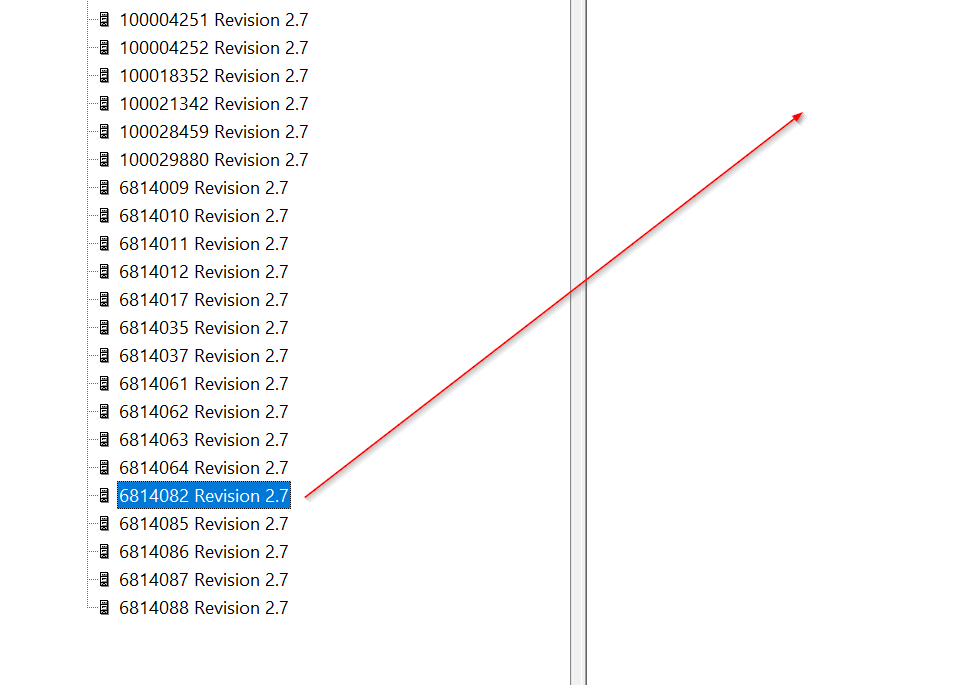
Add Ethernet/IP Adapter
TURCK’s EDS File represents a device by its Ident No. The Ident No. of TBEN-L4-8IOL4 used in this article is 6814082.
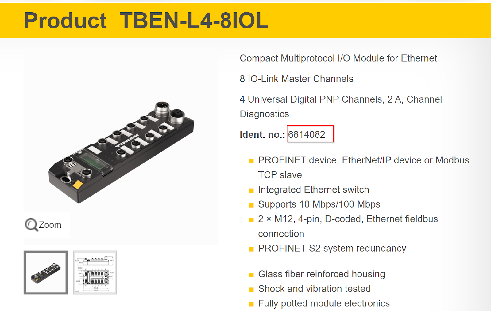
Under Etherent/IP Devices>TURCK>Communication Adapter, select 6814082 that matches the Ident No. of TBEN-L4-8IOL4.
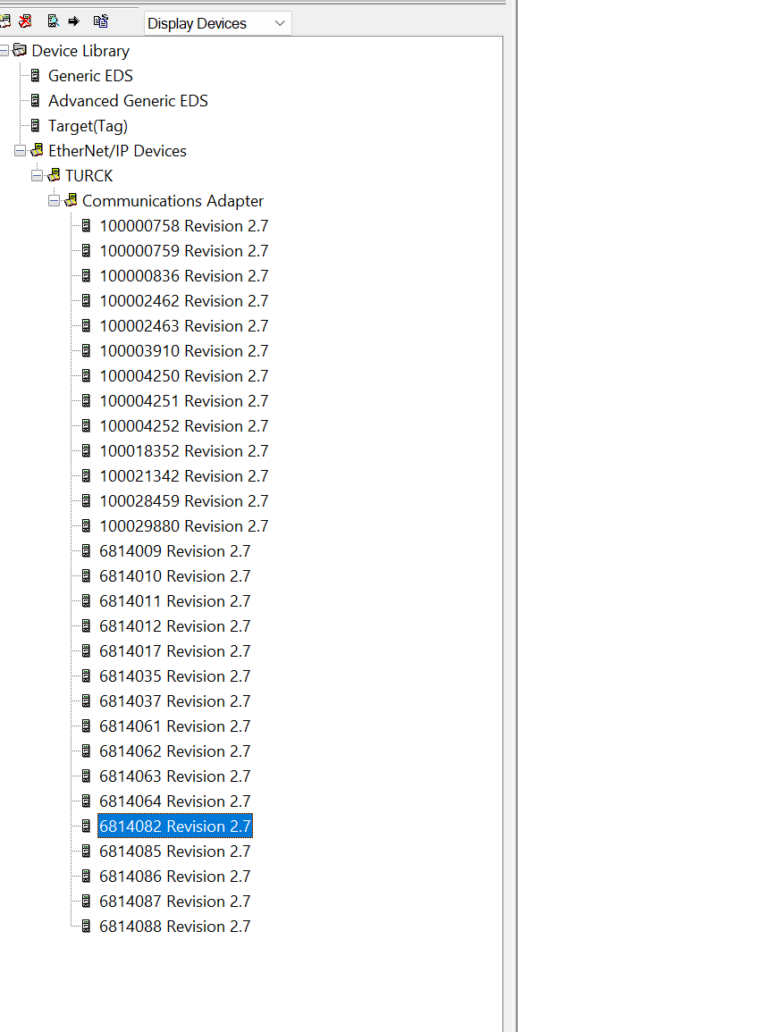
Select 6814082 and Drop in the empty space to the right.
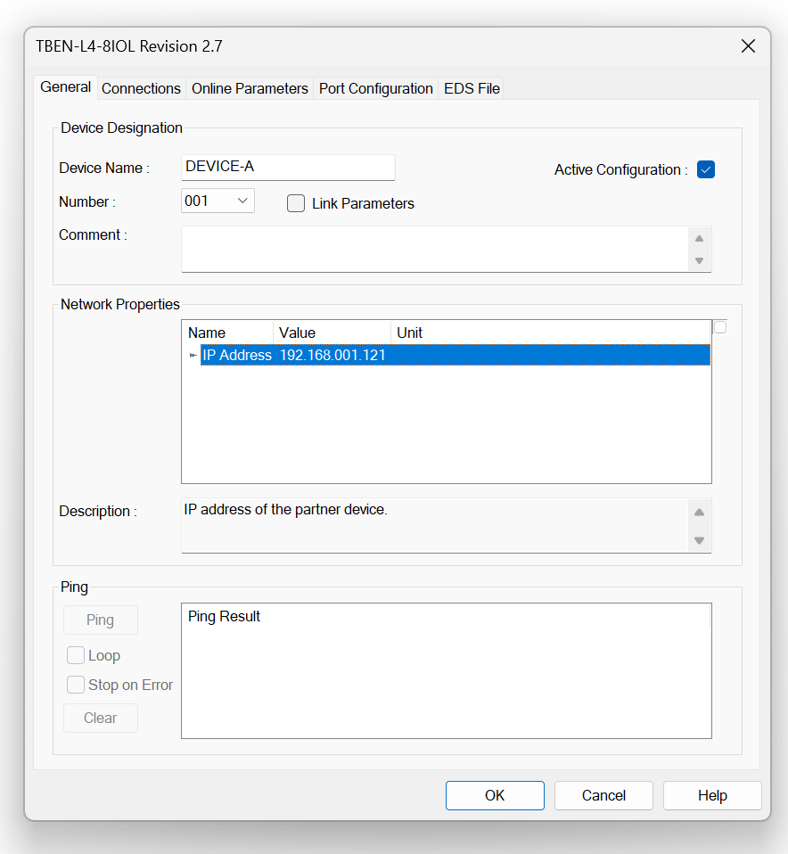
The Etherent/IP Adapter settings are displayed.
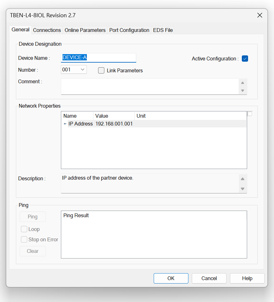
Network Properties
Set the IP address of the TURCK IO-Link Master in Network Properties.
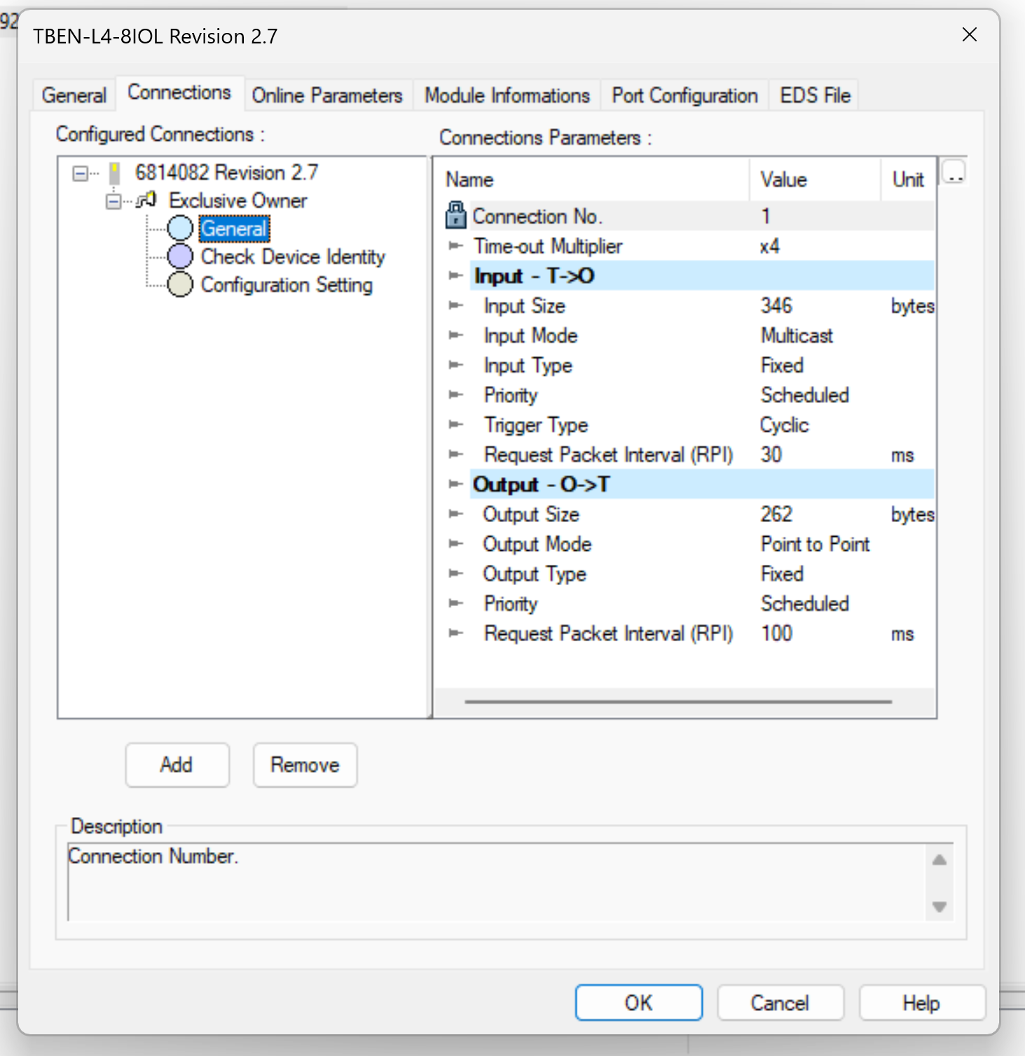
Connections
Connections Tab connects to TURCK’s IO-Link Master, which is the Connection setting.
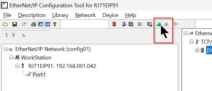
Online
After completing the settings, click the Online button.
Download
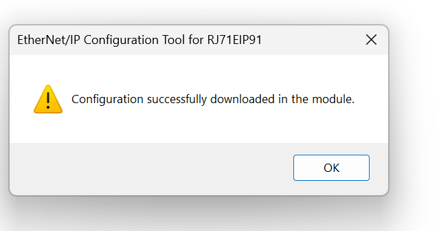
Next, Please download the Configuration.
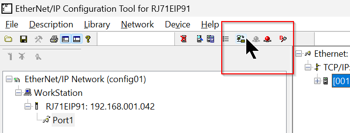
Proceed with Download.
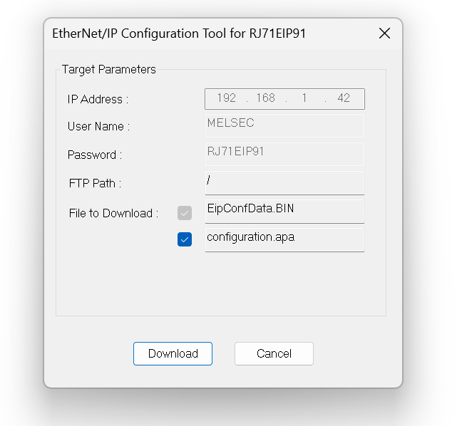
Done!
Program
Once Configuration is complete, it is time to create the program.
Structured Data Types
DUT_TBEN_L4_8IOL_Instance103
This structure is a summary of Instance103 data for TBEN-L4-8IOL4.
| w00StatusWord Word [Signed] w01Inputs Word [Signed] w02DVS Word [Signed] Port1 Word [Signed](0..15) Port2 Word [Signed](0..15) Port3 Word [Signed](0..15) Port4 Word [Signed](0..15) Port5 Word [Signed](0..15) Port6 Word [Signed](0..15) Port7 Word [Signed](0..15) Port8 Word [Signed](0..15) VERR Word [Signed] DXP Word [Signed] DiagnosticPort1 Word [Signed] DiagnosticsPort2 Word [Signed] DiagnosticsPort3 Word [Signed] DiagnosticsPort4 Word [Signed] DiagnosticsPort5 Word [Signed] DiagnosticsPort6 Word [Signed] DiagnosticsPort7 Word [Signed] DiagnosticsPort8 Word [Signed] IOLinkEvents01 Word [Signed](0..1) IOLinkEvents02 Word [Signed](1..2) IOLinkEvents03 Word [Signed](1..2) IOLinkEvents04 Word [Signed](1..2) IOLinkEvents05 Word [Signed](1..2) IOLinkEvents06 Word [Signed](1..2) IOLinkEvents07 Word [Signed](1..2) IOLinkEvents08 Word [Signed](1..2) IOLinkEvents09 Word [Signed](1..2) IOLinkEvents10 Word [Signed](1..2) IOLinkEvents11 Word [Signed](1..2) IOLinkEvents12 Word [Signed](1..2) IOLinkEvents13 Word [Signed](1..2) IOLinkEvents14 Word [Signed](1..2) IOLinkEvents15 Word [Signed](1..2) IOLinkEvents16 Word [Signed](1..2) |
DUT_TBEN_L4_8IOL_Instance104
This structure is a summary of the Instance104 data for TBEN-L4-8IOL4.
| w00NotUsed Word [Signed] w01DXP Word [Signed] Port1 Word [Signed](0..15) Port2 Word [Signed](0..15) Port3 Word [Signed](0..15) Port4 Word [Signed](0..15) Port5 Word [Signed](0..15) Port6 Word [Signed](0..15) Port7 Word [Signed](0..15) Port8 Word [Signed](0..15) VAUX Word [Signed] |
DUT_TURCK_DVS
This structure is a structure that summarizes the DVS data for TBEN-L4-8IOL4.
| DVS0 Bit DVS2 Bit DVS4 Bit DVS6 Bit DVS8 Bit DVS10 Bit DVS12 Bit DVS14 Bit |
DUT_TURCK_VAUX
This structure will be the structure that summarizes the VAUX data for TBEN-L4-8IOL4.
| b0VAUX1Pin1C0 Bit b1VAUX1Pin1C1 Bit b2VAUX1Pin1C2 Bit b3VAUX1Pin1C3 Bit b4VAUX1Pin1C4 Bit b5VAUX1Pin1C5 Bit b6VAUX1Pin1C6 Bit b7VAUX1Pin1C7 Bit b8NoUsed Bit b9NoUsed Bit bANoUsed Bit bBNoUsed Bit bCVAUX1Pin2C4 Bit bDVAUX1Pin2C5 Bit bEVAUX1Pin2C6 Bit bFVAUX1Pin2C7 Bit |
DUT_TURCK_IOILINKPORT_Diagnostics
This structure is a structure that summarizes the IO-Link Port diagnostic data of TBEN-L4-8IOL4.
| b0NotUsed Bit b1PPR Bit b2CFGERR Bit b3DSERR Bit b4HWERR Bit b5PDINV Bit b6EVT2 Bit b7EVT1 Bit b8PRMERR Bit b9OTMP Bit bALLVU Bit bBULVE Bit bCVLOW Bit bDVHIGH Bit bEOVL Bit bFGENERR Bit |
DUT_IOLINK_EVENT_SQ_QUALIFIER_INSTANCE
This structure is the Instance part of IO-Link Event Qualifier.
| bUnknown Bit bNotUsed Bit bApplications Bit |
DUT_IOLINK_EVENT_SQ_QUALIFIER_SOURCE
This structure is the Source portion of the IO-Link Event Qualifier.
| bIsMaster Bit bIsDevice Bit |
DUT_IOLINK_EVENT_SQ_QUALIFIER_MODE
This structure is the Mode portion of the IO-Link Event Qualifier.
| bNotUsed Bit bEventSingleShot Bit bEventDisappears Bit bEventAppears Bit |
DUT_IOLINK_EVENT_SQ_QUALIFIER_TYPE
This structure is the TYPE portion of the IO-Link Event Qualifier.
| bNotUsed Bit bNotification Bit bWarning Bit bError Bit |
DUT_IOLINK_EVENT_SQ_QUALIFIER
This structure is a collection of Instance, Source, Type, and Mode of IO-Link Event Qualifier.
| Instance DUT_IOLINK_EVENT_SQ_QUALIFIER_INSTANCE Source DUT_IOLINK_EVENT_SQ_QUALIFIER_SOURCE EvType DUT_IOLINK_EVENT_SQ_QUALIFIER_TYPE EveMode DUT_IOLINK_EVENT_SQ_QUALIFIER_MODE |
DUT_TURCK_IOLINK_EVENTS
This structure is the EVENTS structure of TBEN-L4-8IOL4. It contains Qualifier, Event Code, Port, and Details defined earlier.
| Port Word [Unsigned]/Bit String [16-bit] Qualifier Word [Unsigned]/Bit String [16-bit] EventCode Word [Signed] Details DUT_IOLINK_EVENT_SQ_QUALIFIER |
DUT_Murr_59719
This is the structure of murrelektronik’s IO-Link Hub 59719.
| b0Pin4X0 Bit b1Pin2X0 Bit b2Pin4X1 Bit b3Pin2X1 Bit b4Pin4X2 Bit b5Pin2X2 Bit b6Pin4X3 Bit b7Pin2X3 Bit b8Pin4X4 Bit b9Pin2X4 Bit bAPin4X5 Bit bBPin2X5 Bit bCPin4X6 Bit bDPin2X6 Bit bEPin4X7 Bit bFPin2X7 Bit |
DUT_Contrinex_IDWE_SENSOR
This is the structure that brings together Contrinex’s IDWE series.
| b0OSS1 Bit b1OSS2 Bit b2TSS Bit b3SSC1 Bit b4SCC2 Bit b5ALR1 Bit b6ALR2 Bit b7ALR3 Bit r32ScaleValue FLOAT [Single Precision] r32MeasureValue FLOAT [Single Precision] |
Function
The next step is to create a function to retrieve Events and diagnostic information in Turck’s IO-Link Master Instance 103.
FC_TURCK_GetEVENTS
This one takes out Events in TUCK’s IO-Link Master Instance 103.
VAR
| iData Word [Signed](1..2) VAR_INPUT bENOTEMP Bit VAR tempWord Word [Unsigned]/Bit String [16-bit] VAR tempWord2 Word [Unsigned]/Bit String [16-bit] VAR |
Code
| //Q WAND(TRUE,iData[1],16#00FF,FC_TURCK_GetEVENTS.Qualifier); //Port WAND(TRUE,iData[1],16#FF00,tempWord); tempWord:=SHR_E(TRUE,bENOTEMP,tempWord,8); FC_TURCK_GetEVENTS.Port:=tempWord; //EventCode FC_TURCK_GetEVENTS.EventCode:=iData[2]; tempWord:=FC_TURCK_GetEVENTS.Qualifier; // FC_TURCK_GetEVENTS.Details.EveMode.bEventAppears:=FALSE; FC_TURCK_GetEVENTS.Details.EveMode.bEventDisappears:=FALSE; FC_TURCK_GetEVENTS.Details.EveMode.bEventSingleShot:=FALSE; FC_TURCK_GetEVENTS.Details.EveMode.bNotUsed:=FALSE; // FC_TURCK_GetEVENTS.Details.EvType.bError:=FALSE; FC_TURCK_GetEVENTS.Details.EvType.bNotification:=FALSE; FC_TURCK_GetEVENTS.Details.EvType.bNotUsed:=FALSE; FC_TURCK_GetEVENTS.Details.EvType.bWarning:=FALSE; // FC_TURCK_GetEVENTS.Details.Instance.bApplications:=FALSE; FC_TURCK_GetEVENTS.Details.Instance.bNotUsed:=FALSE; FC_TURCK_GetEVENTS.Details.Instance.bUnknown:=FALSE; // FC_TURCK_GetEVENTS.Details.Source.bIsDevice:=FALSE; FC_TURCK_GetEVENTS.Details.Source.bIsMaster:=FALSE; IF tempWord >0 THEN // WAND(TRUE,tempWord,2#00000111,tempWord2); CASE WORD_TO_INT(tempWord2) OF 0: FC_TURCK_GetEVENTS.Details.Instance.bUnknown:=TRUE; 1..3,5..7: FC_TURCK_GetEVENTS.Details.Instance.bNotUsed:=TRUE; 4: FC_TURCK_GetEVENTS.Details.Instance.bApplications:=TRUE; END_CASE; // WAND(TRUE,tempWord,2#00001000,tempWord2); tempWord2:=SHR_E(TRUE,bENOTEMP,tempWord2,3); CASE WORD_TO_INT(tempWord2) OF 0: FC_TURCK_GetEVENTS.Details.Source.bIsDevice:=TRUE; 1: FC_TURCK_GetEVENTS.Details.Source.bIsMaster:=TRUE; END_CASE; // WAND(TRUE,tempWord,2#00110000,tempWord2); tempWord2:=SHR_E(TRUE,bENOTEMP,tempWord2,4); CASE WORD_TO_INT(tempWord2) OF 0: FC_TURCK_GetEVENTS.Details.EvType.bNotUsed:=TRUE; 1: FC_TURCK_GetEVENTS.Details.EvType.bNotification:=TRUE; 2: FC_TURCK_GetEVENTS.Details.EvType.bWarning:=TRUE; 3: FC_TURCK_GetEVENTS.Details.EvType.bError:=TRUE; END_CASE; // WAND(TRUE,tempWord,2#11000000,tempWord2); tempWord2:=SHR_E(TRUE,bENOTEMP,tempWord2,6); CASE WORD_TO_INT(tempWord2) OF 0: FC_TURCK_GetEVENTS.Details.EveMode.bNotUsed:=TRUE; 1: FC_TURCK_GetEVENTS.Details.EveMode.bEventSingleShot:=TRUE; 2: FC_TURCK_GetEVENTS.Details.EveMode.bEventDisappears:=TRUE; 3: FC_TURCK_GetEVENTS.Details.EveMode.bEventAppears:=TRUE; END_CASE; END_IF; |
FC_TURCK_GetIOLINKDiagnostics
This one retrieves diagnostic information for each IO-Link Port in TUCK’s IO-Link Master Instance103.
VAR
| iPortData Word [Signed] VAR_INPUT iPortData1 Word [Unsigned]/Bit String [16-bit] VAR |
Code
| iPortData1:=INT_TO_WORD(iPortData); FC_TURCK_GetIOLINKDiagnostics.b0NotUsed:=iPortData1.0; FC_TURCK_GetIOLINKDiagnostics.b1PPR:=iPortData1.1; FC_TURCK_GetIOLINKDiagnostics.b2CFGERR:=iPortData1.2; FC_TURCK_GetIOLINKDiagnostics.b3DSERR:=iPortData1.3; FC_TURCK_GetIOLINKDiagnostics.b4HWERR:=iPortData1.4; FC_TURCK_GetIOLINKDiagnostics.b5PDINV:=iPortData1.5; FC_TURCK_GetIOLINKDiagnostics.b6EVT2:=iPortData1.6; FC_TURCK_GetIOLINKDiagnostics.b7EVT1:=iPortData1.7; FC_TURCK_GetIOLINKDiagnostics.b8PRMERR:=iPortData1.8; FC_TURCK_GetIOLINKDiagnostics.b9OTMP:=iPortData1.9; FC_TURCK_GetIOLINKDiagnostics.bALLVU:=iPortData1.A; FC_TURCK_GetIOLINKDiagnostics.bBULVE:=iPortData1.B; FC_TURCK_GetIOLINKDiagnostics.bCVLOW:=iPortData1.C; FC_TURCK_GetIOLINKDiagnostics.bDVHIGH:=iPortData1.D; FC_TURCK_GetIOLINKDiagnostics.bEOVL:=iPortData1.E; FC_TURCK_GetIOLINKDiagnostics.bFGENERR:=iPortData1.F; |
Function Block
To add GXWORKS Ethernet/IP Library, right click on Module FB>RJ71EIP91>Add to Project.
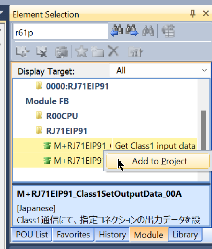
Done!
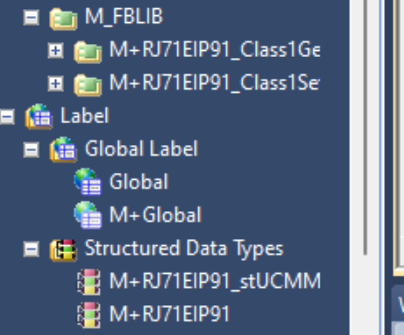
Global Label
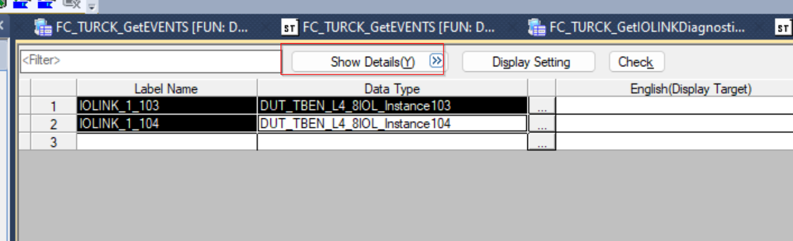
Next, define the area to exchange data with TURCK IO-Linker Master in Global label.
| IOLINK_1_103 DUT_TBEN_L4_8IOL_Instance103 IOLINK_1_104 DUT_TBEN_L4_8IOL_Instance104 |
Click the “Show Details” button on the Global label definition screen.
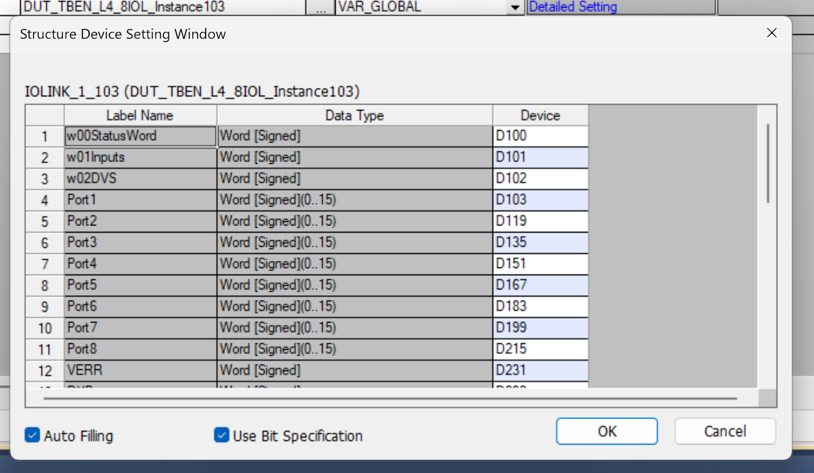
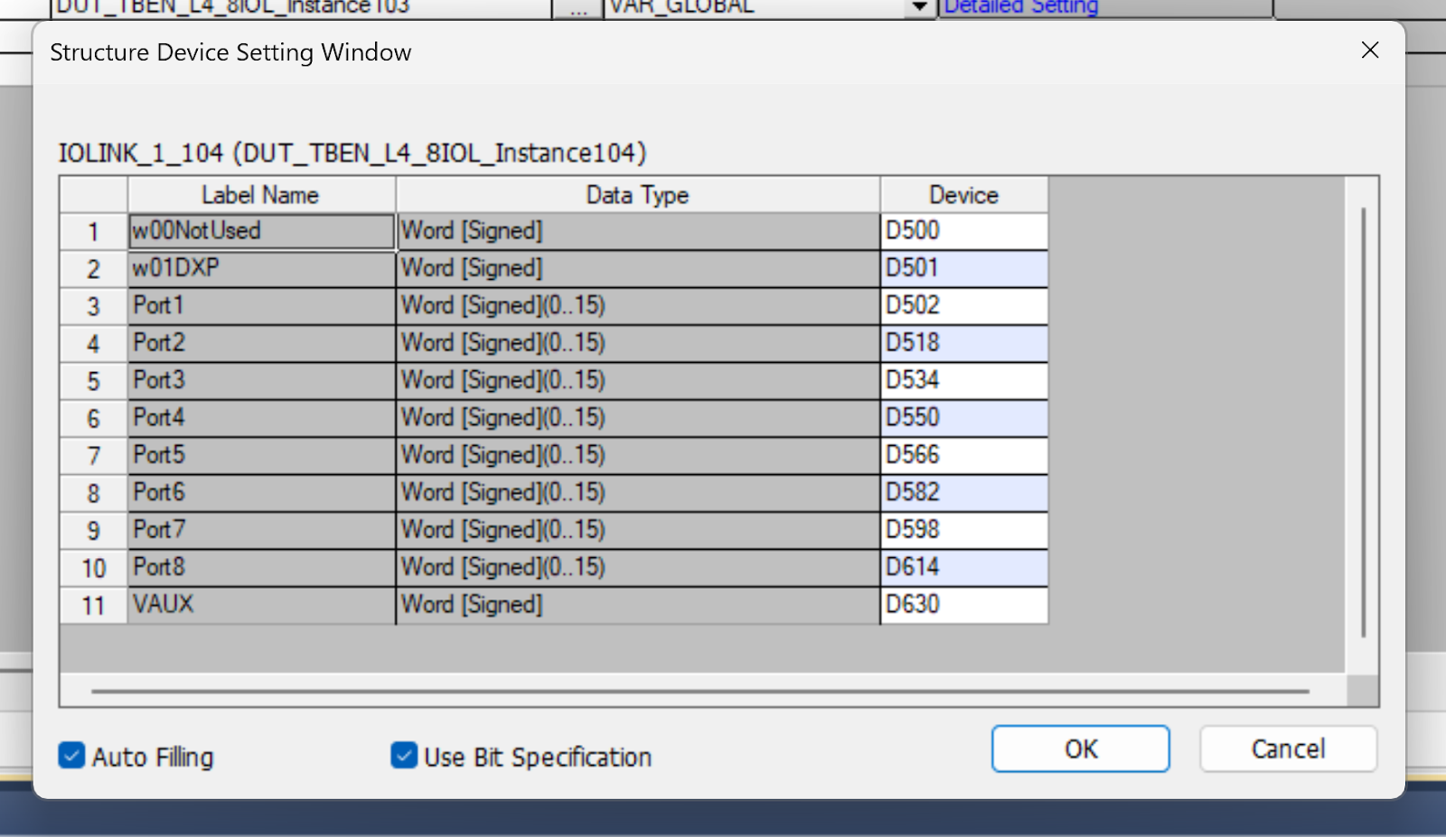
Click Assign(Detailed Setting).
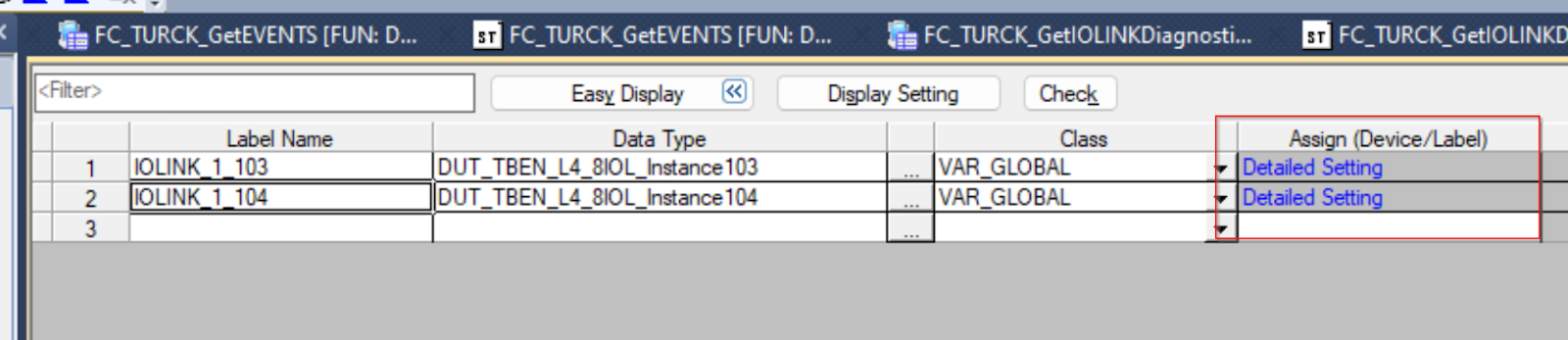
Instance 103 is assigned from D100.
Instance104 is allocated from D500.
MAIN
Next is the Main program.
VAR
| r32Port1Current FLOAT [Single Precision] r32Port1Level FLOAT [Single Precision] r32Temp FLOAT [Single Precision] i16Port4_ProcessDataRev Word [Signed] i16Port4_ProcessData Word [Unsigned]/Bit String [16-bit] i16Port4_Scale Word [Signed] bENOTEMP Bit fbClass1SetOutputData_00A M+RJ71EIP91_Class1SetOutputData_00A i16PWMSetPoint Word [Unsigned]/Bit String [16-bit] udtMurr59719_inputs DUT_Murr_59719 udtMurr59719_outputs DUT_Murr_59719 fbTON1 TON fbTON2 TON udtContrinex_Sensor1 DUT_Contrinex_IDWE_SENSOR iConnetionNO Word [Unsigned]/Bit String [16-bit] udtVAUX DUT_TURCK_VAUX udtVERR DUT_TURCK_VAUX TURCKPortsDiagnostic DUT_TURCK_IOILINKPORT_Diagnostics(1..8) TURCKPortsEvent DUT_TURCK_IOLINK_EVENTS(1..4) |
Code
The program is not described in detail, but it uses Mitsubishi’s Library to retrieve data from Connection1 and process the data by each Port and the IO-Link device connected to it.
The last step is again to use Mitsubishi’s Library and write the output data to Connection1.
| //Connections iConnetionNO:=1; //1s Pulse fbTON1( IN:= NOT fbTON2.Q ,PT:= T#1s //,Q=> ?BOOL? ,ET=> ?TIME? ); fbTON2( IN:= fbTON1.Q ,PT:= T#1s //,Q=> ?BOOL? ,ET=> ?TIME? ); //Start2Communication bStart2Comm:=EIP91_1.bSts_ModuleReady AND NOT EIP91_1.bSts_ModuleError; EIP91_1.bSet_CommunicationStartupRequest:=bStart2Comm; //Case Control IF i16Step = 0 AND bStart2Comm THEN i16Step:=10; END_IF; CASE i16Step OF 10: fbClass1GetInputData_00A( i_bEN:= bStart2Comm ,i_stModule:= EIP91_1 ,i_uConnectionNo:= iConnetionNO ,o_bENO=> bENO ,o_bOK=> bOK ,o_bErr=> bErr ,o_uErrId=> uErrID ,o_uStatusId=> uStatusID ,o_uInputData=> D100 ); IF bErr THEN i16Step:=20; END_IF; 20: fbClass1GetInputData_00A( i_bEN:= FALSE ,i_stModule:= EIP91_1 ,i_uConnectionNo:= iConnetionNO ,o_bENO=> bENO ,o_bOK=> bOK ,o_bErr=> bErr ,o_uErrId=> uErrID ,o_uStatusId=> uStatusID ,o_uInputData=> D100 ); i16Step:=0; END_CASE; //Process Input data valid udtDVS.DVS0:=IOLINK_1_103.w02DVS.0; udtDVS.DVS2:=IOLINK_1_103.w02DVS.2; udtDVS.DVS4:=IOLINK_1_103.w02DVS.4; udtDVS.DVS6:=IOLINK_1_103.w02DVS.6; udtDVS.DVS8:=IOLINK_1_103.w02DVS.8; udtDVS.DVS10:=IOLINK_1_103.w02DVS.A; udtDVS.DVS12:=IOLINK_1_103.w02DVS.C; udtDVS.DVS14:=IOLINK_1_103.w02DVS.E; //Port1 Murr, Analog->IOLINK Converter r32Port1Current:= (INT_TO_REAL(IOLINK_1_103.Port1[0])/32767.0)*20.0+4.0; r32Port1Level:= (INT_TO_REAL(IOLINK_1_103.Port1[0])/32767.0)*100.0; //Port4 Turck Sensor i16Port4_ProcessDataRev:=IOLINK_1_103.Port4[0]; i16Port4_ProcessData:=INT_TO_WORD(IOLINK_1_103.Port4[1]); //Port5 Nass // IOLINK_1_104.Port5[0].0:=M101; i16PWMSetPoint:=D1003; IOLINK_1_104.Port5[0].1:=i16PWMSetPoint.0; IOLINK_1_104.Port5[0].2:=i16PWMSetPoint.1; IOLINK_1_104.Port5[0].3:=i16PWMSetPoint.2; IOLINK_1_104.Port5[0].4:=i16PWMSetPoint.3; IOLINK_1_104.Port5[0].5:=i16PWMSetPoint.4; IOLINK_1_104.Port5[0].6:=i16PWMSetPoint.5; IOLINK_1_104.Port5[0].7:=i16PWMSetPoint.6; IOLINK_1_104.Port5[0].8:=i16PWMSetPoint.7; //Port7 Murr IOLINK-hub // udtMurr59719_inputs.b0Pin4X0:=IOLINK_1_103.Port7[0].0; udtMurr59719_inputs.b1Pin2X0:=IOLINK_1_103.Port7[0].1; udtMurr59719_inputs.b2Pin4X1:=IOLINK_1_103.Port7[0].2; udtMurr59719_inputs.b3Pin2X1:=IOLINK_1_103.Port7[0].3; udtMurr59719_inputs.b4Pin4X2:=IOLINK_1_103.Port7[0].4; udtMurr59719_inputs.b5Pin2X2:=IOLINK_1_103.Port7[0].5; udtMurr59719_inputs.b6Pin4X3:=IOLINK_1_103.Port7[0].6; udtMurr59719_inputs.b7Pin2X3:=IOLINK_1_103.Port7[0].7; udtMurr59719_inputs.b8Pin4X4:=IOLINK_1_103.Port7[0].8; udtMurr59719_inputs.b9Pin2X4:=IOLINK_1_103.Port7[0].9; udtMurr59719_inputs.bAPin4X5:=IOLINK_1_103.Port7[0].A; udtMurr59719_inputs.bBPin2X5:=IOLINK_1_103.Port7[0].B; udtMurr59719_inputs.bCPin4X6:=IOLINK_1_103.Port7[0].C; udtMurr59719_inputs.bDPin2X6:=IOLINK_1_103.Port7[0].D; udtMurr59719_inputs.bEPin4X7:=IOLINK_1_103.Port7[0].E; udtMurr59719_inputs.bFPin2X7:=IOLINK_1_103.Port7[0].F; // udtMurr59719_outputs.b6Pin4X3:=fbTON1.Q; IOLINK_1_104.Port7[0].5:=udtMurr59719_outputs.b6Pin4X3; // udtContrinex_Sensor1.b0OSS1:=IOLINK_1_103.Port8[1].0; udtContrinex_Sensor1.b1OSS2:=IOLINK_1_103.Port8[1].1; udtContrinex_Sensor1.b2TSS:=IOLINK_1_103.Port8[1].2; udtContrinex_Sensor1.b3SSC1:=IOLINK_1_103.Port8[1].3; udtContrinex_Sensor1.b4SCC2:=IOLINK_1_103.Port8[1].4; udtContrinex_Sensor1.b5ALR1:=IOLINK_1_103.Port8[1].5; udtContrinex_Sensor1.b6ALR2:=IOLINK_1_103.Port8[1].6; udtContrinex_Sensor1.b7ALR3:=IOLINK_1_103.Port8[1].7; bENOTEMP:=WAND(TRUE,IOLINK_1_103.Port8[1],16#FF00,D1000); D1001:=SHR_E(TRUE,bENOTEMP,D1000,8); udtContrinex_Sensor1.r32ScaleValue:=INT_TO_REAL(D1001); udtContrinex_Sensor1.r32MeasureValue:= (INT_TO_REAL(IOLINK_1_103.Port8[0])/16384.0)*110.0; //VERR udtVERR.b0VAUX1Pin1C0:=IOLINK_1_103.VERR.0; udtVERR.b1VAUX1Pin1C1:=IOLINK_1_103.VERR.1; udtVERR.b2VAUX1Pin1C2:=IOLINK_1_103.VERR.2; udtVERR.b3VAUX1Pin1C3:=IOLINK_1_103.VERR.3; udtVERR.b4VAUX1Pin1C4:=IOLINK_1_103.VERR.4; udtVERR.b5VAUX1Pin1C5:=IOLINK_1_103.VERR.5; udtVERR.b6VAUX1Pin1C6:=IOLINK_1_103.VERR.6; udtVERR.b7VAUX1Pin1C7:=IOLINK_1_103.VERR.7; udtVERR.b8NoUsed:=IOLINK_1_103.VERR.8; udtVERR.b9NoUsed:=IOLINK_1_103.VERR.9; udtVERR.bANoUsed:=IOLINK_1_103.VERR.A; udtVERR.bBNoUsed:=IOLINK_1_103.VERR.B; udtVERR.bCVAUX1Pin2C4:=IOLINK_1_103.VERR.C; udtVERR.bDVAUX1Pin2C5:=IOLINK_1_103.VERR.D; udtVERR.bEVAUX1Pin2C6:=IOLINK_1_103.VERR.E; udtVERR.bFVAUX1Pin2C7:=IOLINK_1_103.VERR.F; //Port Diagnostics TURCKPortsDiagnostic[1]:=FC_TURCK_GetIOLINKDiagnostics( bStart2Comm ,bENOTEMP ,IOLINK_1_103.DiagnosticPort1 ); TURCKPortsDiagnostic[2]:=FC_TURCK_GetIOLINKDiagnostics( bStart2Comm ,bENOTEMP ,IOLINK_1_103.DiagnosticsPort2 ); TURCKPortsDiagnostic[3]:=FC_TURCK_GetIOLINKDiagnostics( bStart2Comm ,bENOTEMP ,IOLINK_1_103.DiagnosticsPort3 ); TURCKPortsDiagnostic[4]:=FC_TURCK_GetIOLINKDiagnostics( bStart2Comm ,bENOTEMP ,IOLINK_1_103.DiagnosticsPort4 ); TURCKPortsDiagnostic[5]:=FC_TURCK_GetIOLINKDiagnostics( bStart2Comm ,bENOTEMP ,IOLINK_1_103.DiagnosticsPort5 ); TURCKPortsDiagnostic[6]:=FC_TURCK_GetIOLINKDiagnostics( bStart2Comm ,bENOTEMP ,IOLINK_1_103.DiagnosticsPort6 ); TURCKPortsDiagnostic[7]:=FC_TURCK_GetIOLINKDiagnostics( bStart2Comm ,bENOTEMP ,IOLINK_1_103.DiagnosticsPort7 ); TURCKPortsDiagnostic[8]:=FC_TURCK_GetIOLINKDiagnostics( bStart2Comm ,bENOTEMP ,IOLINK_1_103.DiagnosticsPort8 ); //IOLINK Events TURCKPortsEvent[1]:=FC_TURCK_GetEVENTS( bStart2Comm ,bENOTEMP ,IOLINK_1_103.IOLinkEvents01 ); // fbClass1SetOutputData_00A( i_bEN:= bStart2Comm ,i_stModule:= EIP91_1 ,i_uConnectionNo:= iConnetionNO ,i_uOutputData:= D500 ,o_bENO=> bENO ,o_bOK=> bOK ,o_bErr=> bErr ,o_uErrId=> uErrID ,o_uStatusId=> uStatusID ); ; |
Result
Here is a video showing how TURCK IO-Link Master and contrinex Smart Sensor work together.
Here is a video of TURCK IO-Link Master and murrelektronik IO-Link Converter working together.
Here is a video of TURCK IO-Link Master processing an Event.
Here is a video of TURCK IO-Link Master and murrelektronik IO-Link Hub working together.
Here is a video of TURCK IO-Link Master and Nass magnet devices working together.
Here is a video of TURCK IO-Link Master and TURCK devices working together.
Download
Download the project at the link below.
https://github.com/soup01Threes/GXWROKS/blob/main/Project_RJ71EIP91_TURCK.gx3