This is a new series of articles on various topics using Schmersal’s PSC1-C-100-FB1 Safety Controller.Episode 2 is connected to emergency stop and creating a safety program.
Come on, let’s enjoy FA.
Foreword
Thank you from the bottom of my heart for visiting my technical blog and YouTube channel.
We are currently running the “Takahashi Chris” radio show with Full-san (full@桜 八重 (@fulhause) / X) which I deliver every Wednesday night.
Sharing, not hoarding, technical knowledge
We publish technical information related to factory production technology and control systems for free, through blogs and videos.
With the belief that “knowledge should be accessible to everyone,” we share practical know-how and real-world troubleshooting cases from our own field experience.
The reason we keep it all free is simple: to help reduce the number of people who struggle because they simply didn’t know.
If you’ve ever thought:
- “Will this PLC and device combination actually work?”
- “I’m having trouble with EtherCAT communication—can someone test it?”
- “I want to try this remote I/O, but we don’t have the testing environment in-house…”
Feel free to reach out!If lending equipment or sharing your configuration is possible, we’re happy to verify it and share the results through articles and videos.
(We can keep company/product names anonymous if requested.)
How can you support us?
Currently, our activities are nearly all unpaid, but creating articles and videos takes time and a proper testing environment.If you’d like to support us in continuing and expanding this content, your kind help would mean a lot.
Membership (Support our radio show)
This support plan is designed to enhance radio with Mr Full.
https://note.com/fulhause/membership/join
Amazon Gift List (equipment & books for content production)
Lists equipment and books required for content creation.
https://www.amazon.co.jp/hz/wishlist/ls/H7W3RRD7C5QG?ref_=wl_share
Patreon (Support articles & video creation)
Your small monthly support will help to improve the environment for writing and verifying articles.
https://www.patreon.com/user?u=84249391
Paypal
A little help goes a long way.
https://paypal.me/soup01threes?country.x=JP&locale.x=ja_JP
Just trying to share things that could’ve helped someone—if only they’d known.
Your support helps make knowledge sharing more open and sustainable.
Thank you for being with us.
soup01threes*gmail.com
Technical knowledge shouldn’t be kept to ourselves.
Reference Video
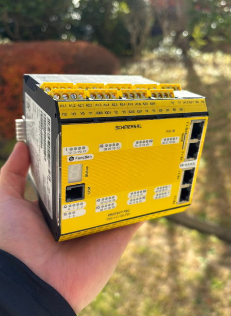
Schmersal.Open box with PSC1-C-100-FB1!
Reference Link
http://soup01.com/en/category/schmersal_en/psc1-en/
Implementation
In this article, the flow is as follows: add each connection input/output component > create safety program > download project.
Add ESTOP
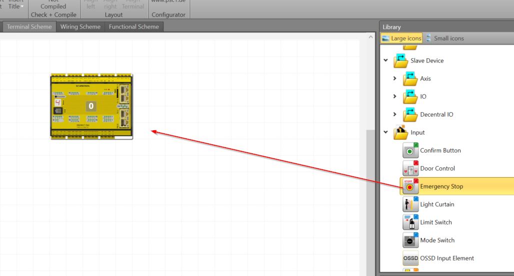
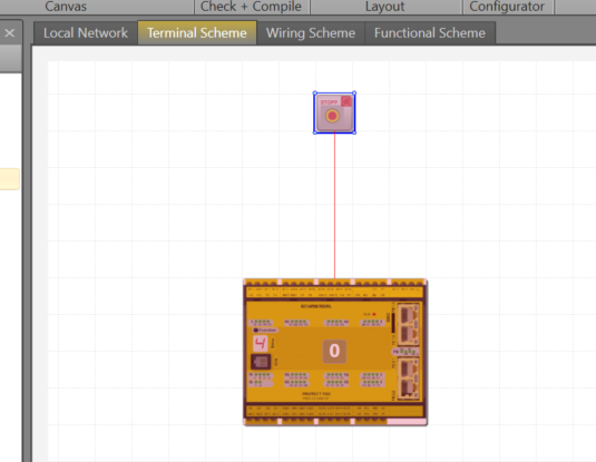
In the previous article, we introduced the basic operation of the Schmersal SafetyPLC2 tool, project creation, etc.We will continue with the previous article by opening the Terminal Scheme Tab>Library>Input>Emergency Stop and adding it to the project.
Done!The emergency stop has been added, but the part itself is still red, so either there is a configuration error or it is not being used within the safety program.
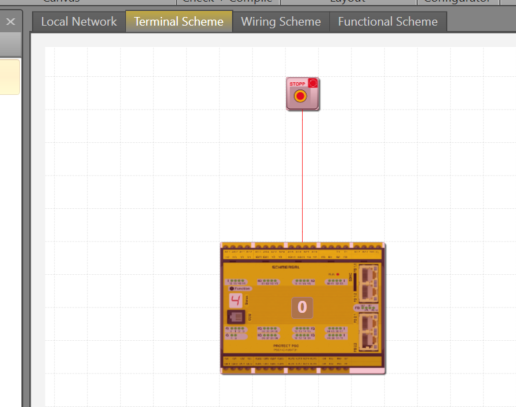
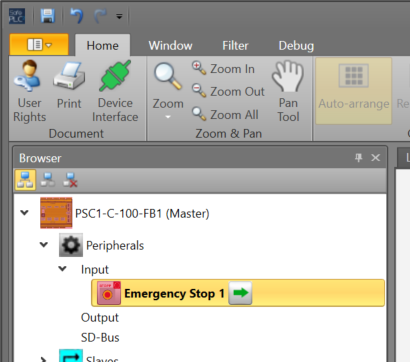
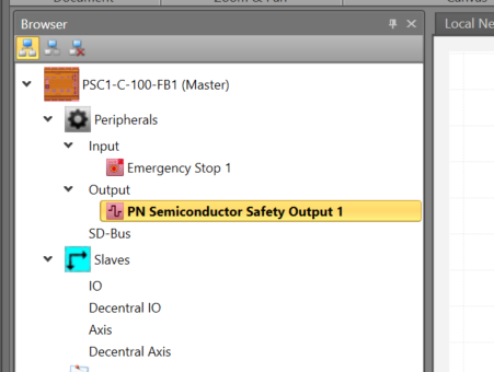
You will also see the emergency stop component you just added in Project>Peripherals>Input.
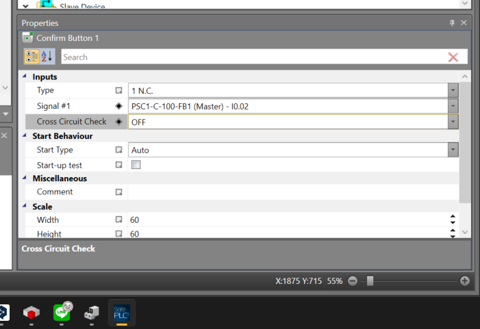
Configure
Now we can set parameters for emergency stop components.
Parameters for the appropriate part can be set from the Properties screen.
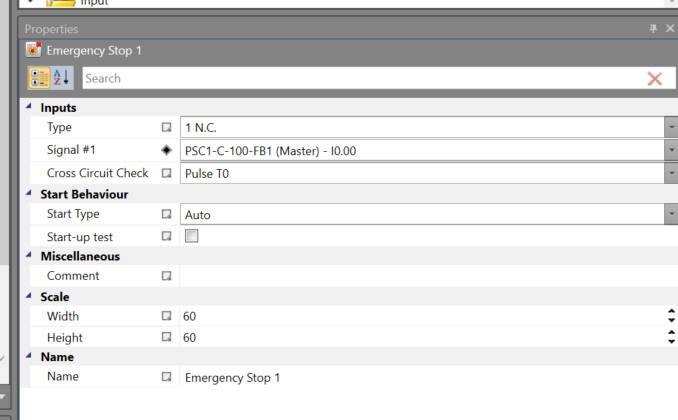
Type
This sets the wiring type of the emergency stop.
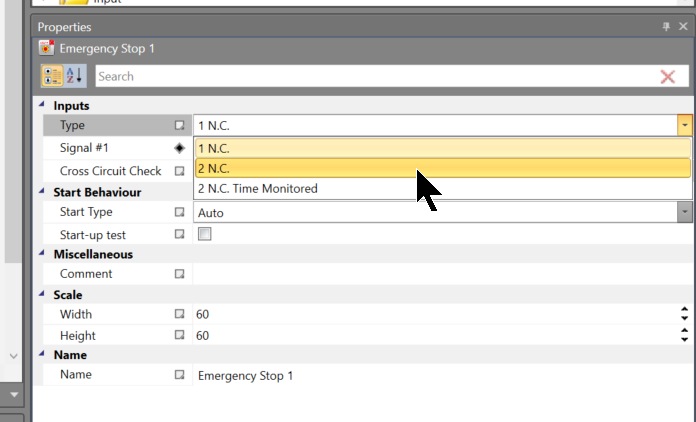
Let’s set it to 2.NC this time.
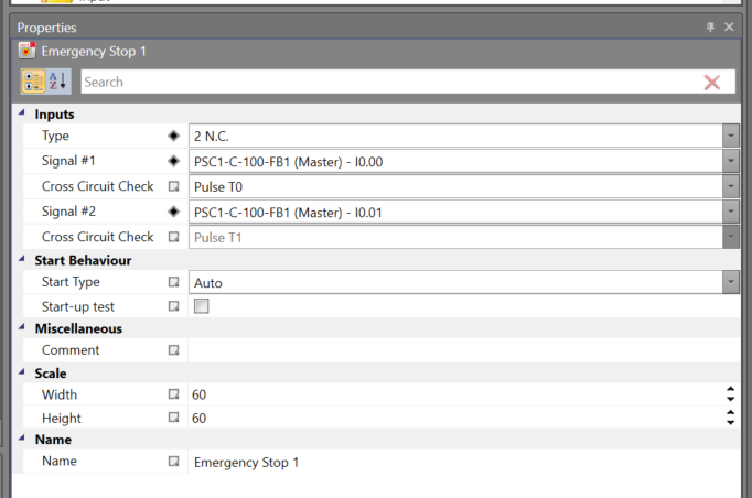
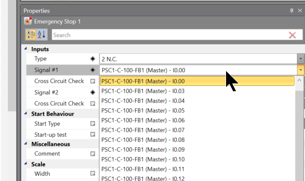
Change IO Signal
You can set the IO pins that you plan to wire to the corresponding component in the Signal #1 item.
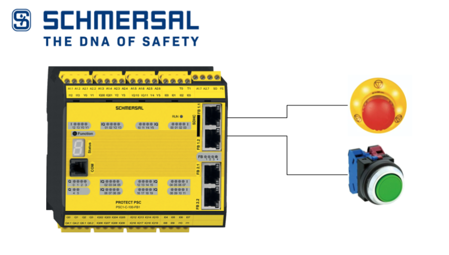
Emergency Stop
Such a switch type can be configured for emergency stop components.
| Type | Design |
| 1 (1 N.C.) | B contact x1 |
| 2 (2 N.C.) | B contact x2 |
| 3 (2 N.C. TimeMonitored) | B contact x2 + time monitoring |
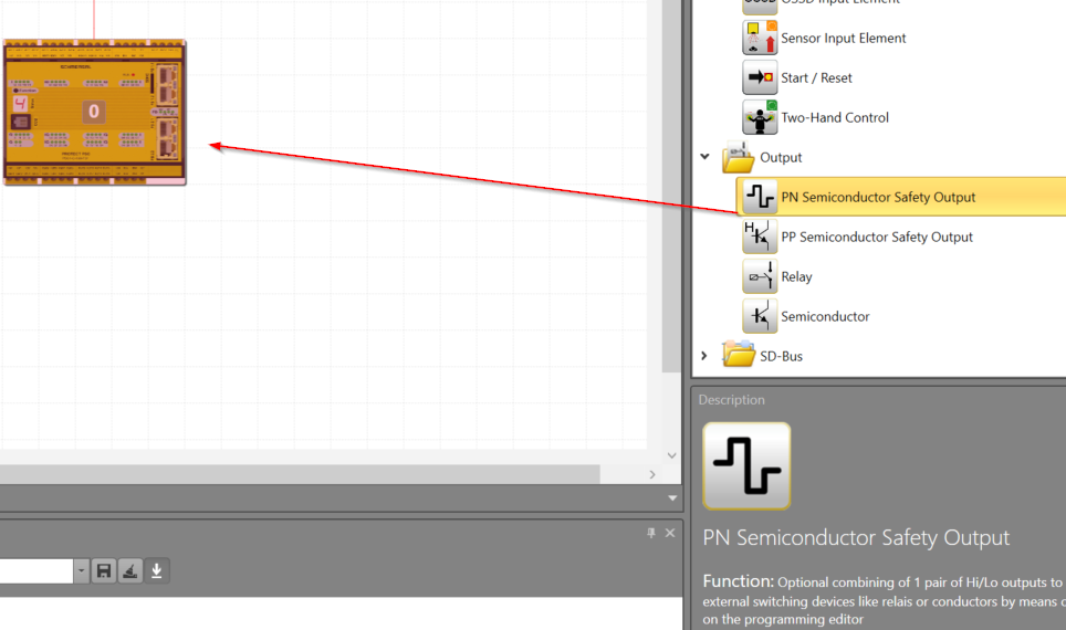
Add Safetey Output
Next, from the Terminal Scheme Tab, add the Output>PN Semicondutor Safety Output component to add the safety output component.
Configure
Set the parameters of the safety output from the Properties screen.In this article, we will set the Output Type to “Standard”.
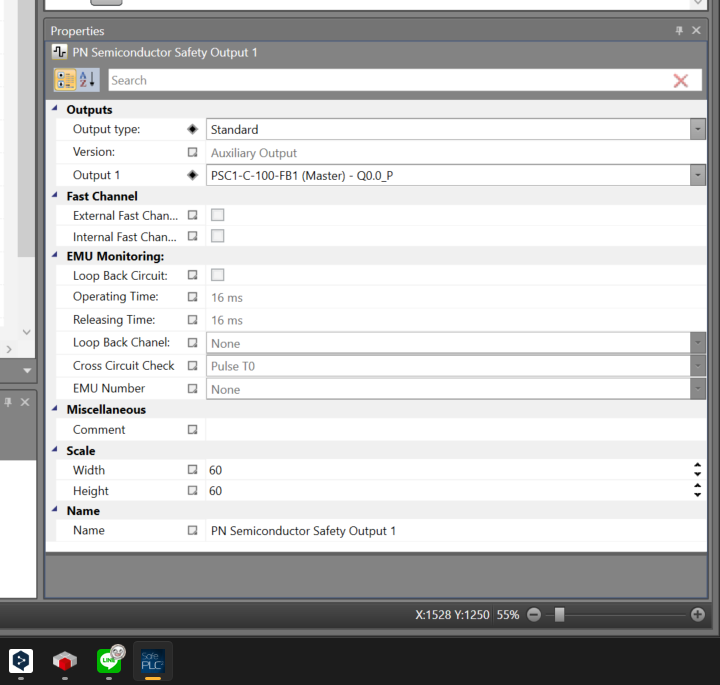
The safety output component you just added appears in Project>Peripherals>Output.
PN semiconductor output
PN半導体出力にはこのような設定が可能です。
| Type | Design |
| Standard | “HISIDE” (=P switching) or “LOSIDE” (=N switching) can be selected as standard output.Can be selected as a standard output (depends on the output used).The use of standard outputs alone is not suitable for safety reasons. |
| Redundant | This option forces a combination of “HISIDE” (=P switching) and “LOSIDE” (=N switching) outputs. |
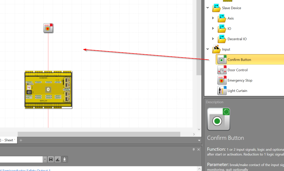
Add Reset Button
The final step is to add a Confirm Button component from the Input Library.
Done!
Configure
Configure the part in Properties.For this fall, just set Type to NO.
Confirm Button
The Confirm Button can be set to this type of switch type.
| Type | Design |
| 1 (1 N.O.) | A contact x1 |
| 2 (1 N.C.) | B contact x1 |
| 3 (2 N.C.) | B contact x2 |
Program
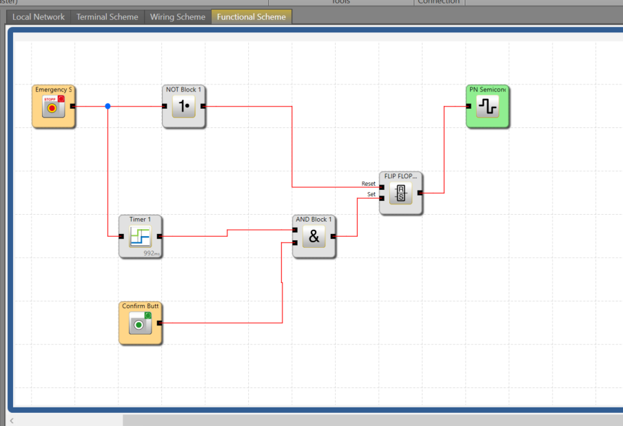
Here is the safety program we created for this article.
- When the Emergency Stop is turned OFF, it fires the Reset input of the FILP FLOP > Resets the FILP output
- When the emergency stop is turned on, it passes through delay Timer1, and when the Confirm Button is pressed again, it fires the SET input of the FILP FLOP > sets the FILP output
- FILP FLOP output is reflected in the output PN Semiconductor just added
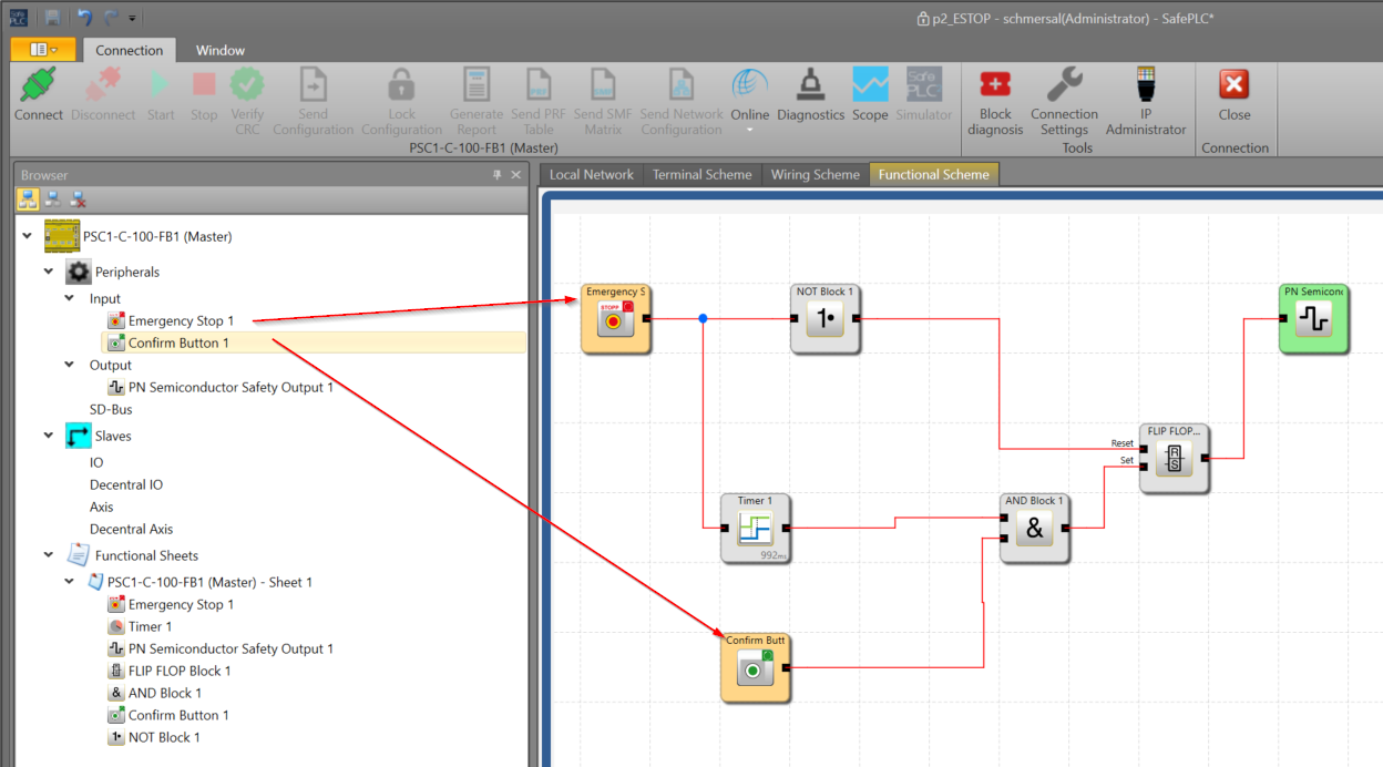
If you want to use the input/output hardware you just added to the safety program, drop it directly in the Browser screen on the left.
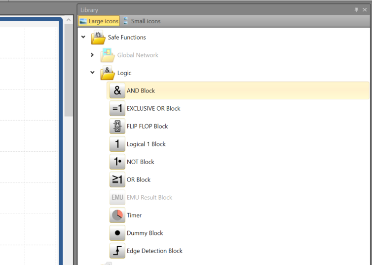
In addition, functions such as AND and OR can be added to the program at Library>Logic.
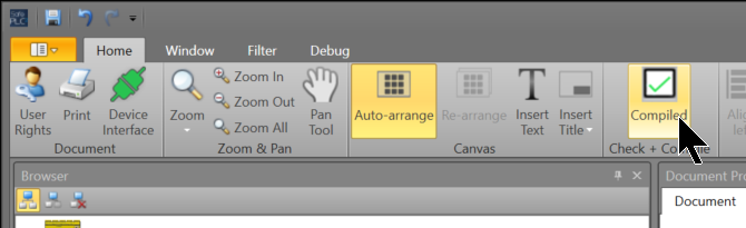
Compile
Click the Compile Project button in the Toolbar to see if there are any errors.
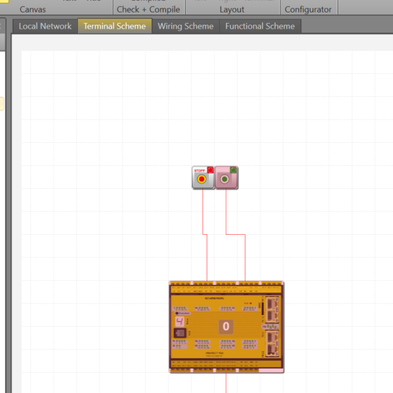
Wiring
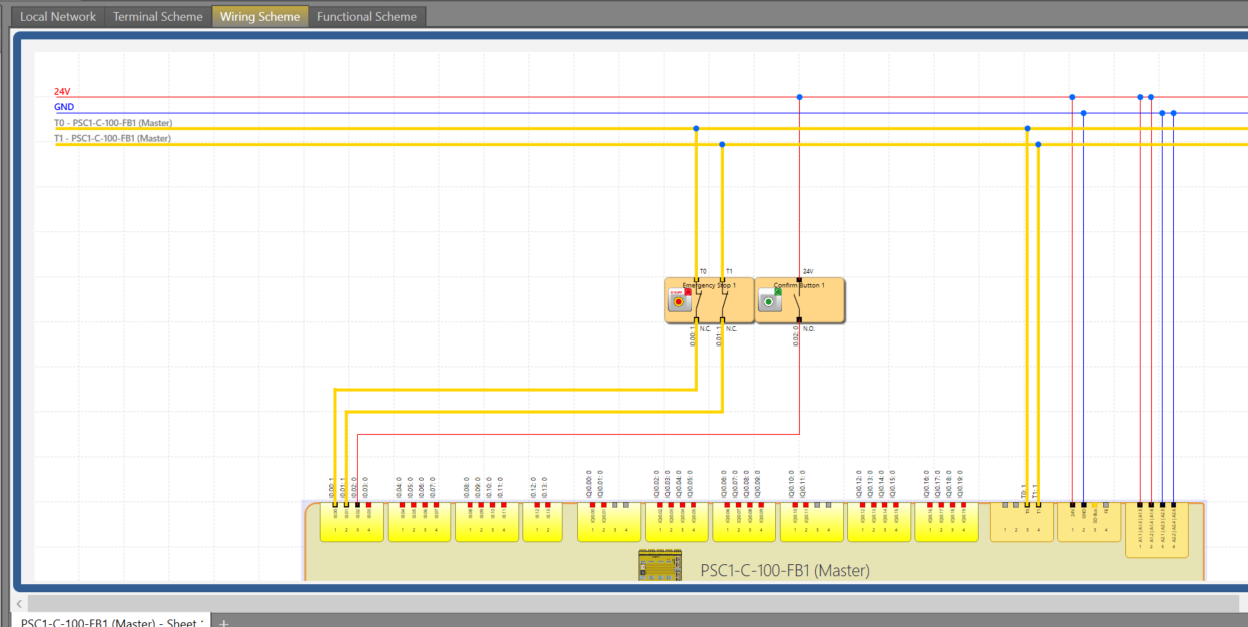
Click on the Wiring Scheme Tab to check the wiring of the PSC1-C-100-FB1.
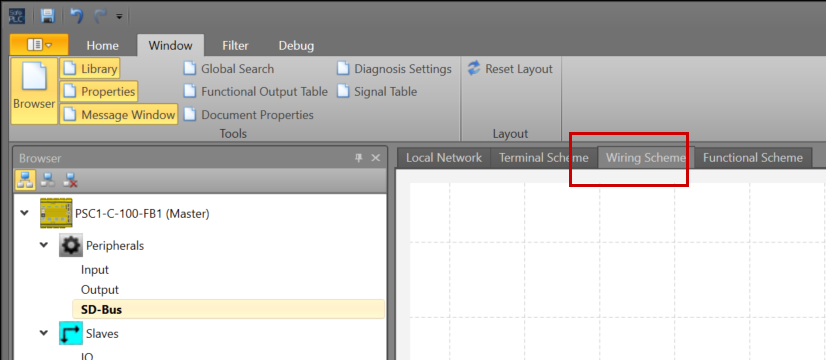
The SafePLC2 tool even automatically generates a wiring diagram for you.
Connect to the Controller
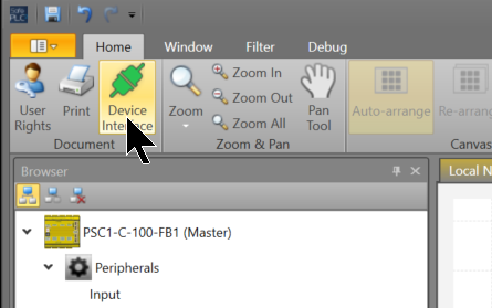
Connect the COM Port of the PSC1-C-100-FB1 and the dedicated cable to the PC.
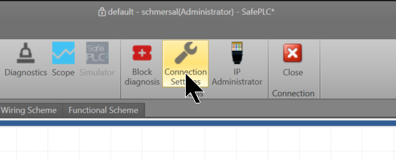
Click SafePLC2>Home>Device Interface.
Click Connection Settings.
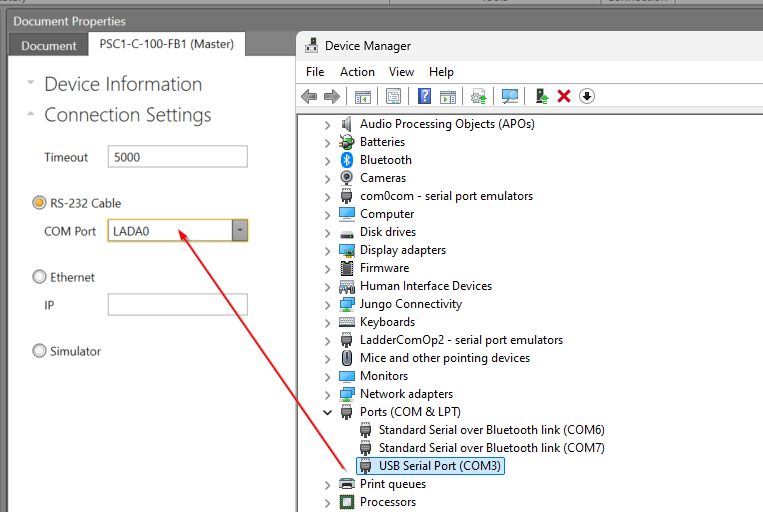
As you will be using an RS-232 cable, you should set the COM Port to match the Device Manager.
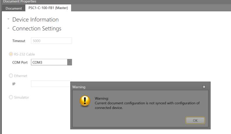
Finally, click the Connect button to connect the CPU and SafePLC2.
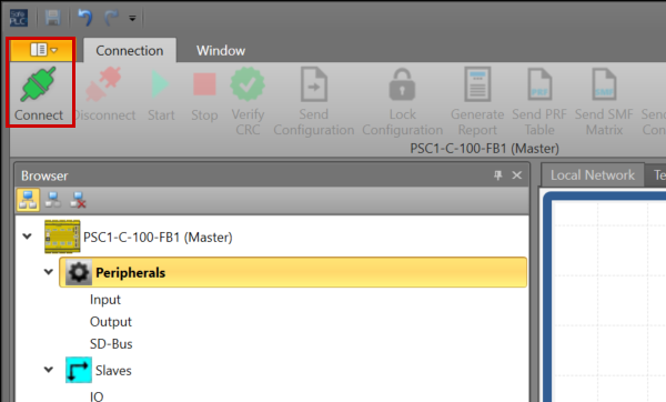
OK to proceed. So I connected the SafePLC2 to the PSC1-C-100-FB1.
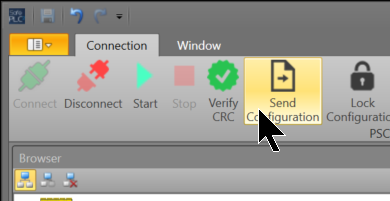
Send Configuration
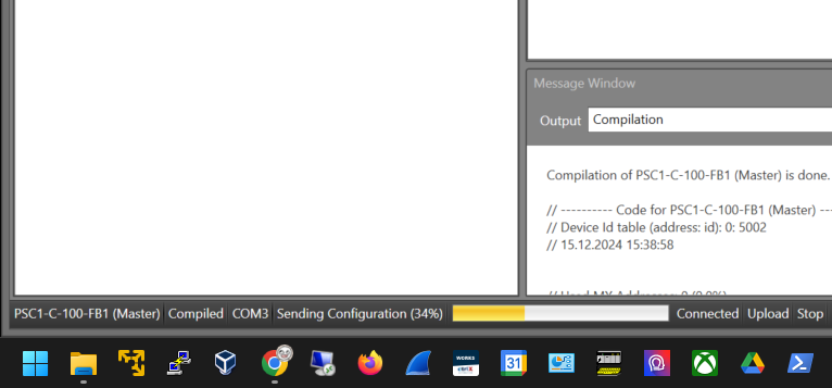
Click Send Configuration to transfer your project to PSC1-C-100-FB1.
しばらくお待ち下さい…
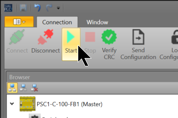
Start
Finally, click the Start button to set the PSC1-C-100-FB1 CPU to RUN MODE.
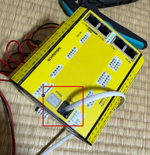
Result
If the PSC1-C-100-FB1 starts up normally, the Status LEC on the PSC1-C-100-FB1 itself will display “4”.
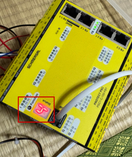
You can check the operation in this video.