Simumatik?
Simumatik is a Swedish company that focuses on making Digital Twins technology easier and more accessible to everyone, providing easy-to-use Platform.
What benefits does Digitial Twins offer to each side??
Now let’s talk about the advantages of using Digital Twins from each Role.
If you are an Industry Professional…
Simumatick is an extension of current simulations and can be further integrated from multiple simulation platforms.It allows you to,
- Lower Physical Commissioning Time and Cost
- Reduce errors and production down time
- Optimize and improve existing systems
- Test PLC/Robot logic
- Train engineers and operators in a virtual environment
It can be supported in many ways.
You’re involved in education.…
In today’s FA industry, technology is constantly being updated, and one major goal of education is to expose students to new technology.Simumatick provides a Virtual Commissioning Platform for education without the need for special software,Simumatick requires no special software, just a Browser and one small Gateway.
If you are a student, you can…
Of course, if you’re a student, even a single real switch/sensor can cost more than a thousand dollars, and robot servo motors are out of reach, but with Platform like Simumatik, combined with a Software PLC like Beckhoff or Codesys, it’s cheaper and moreYou can learn more cheaply and easily.
ClassRoom Concept
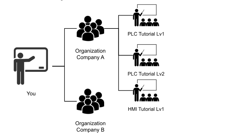
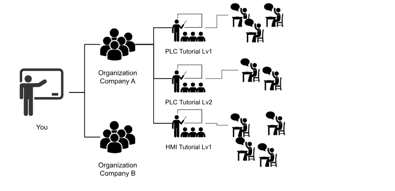
Simimumatik has an interesting concept like ClassRomm.If you are a teacher of training in a company, and you want to use Simumatik, you first create several Organizations, which you group into Company A and Company B. Then you create a new Organization, which you group into Company A and Company B. Then you create a new Organization, which you group into Company B, and so on.

Then, in Organization – Company A, multiple Classrooms are created depending on the content of the training.

At the end of the training course, the student can register his/her email address in the ClassRoom, and when the training begins, he/she can click on the EMAIL LINK to take the class.

When the training is over, you, the teacher, just delete the Classroom in Browser and you are done.There is no complicated operation.

Limitless Integration
Simimumatik also has an assortment of Gateways in Default that connect to various manufacturers in the FA industry.The following are just a few, but there are more than 15 Gateways including Beckhoff ADS, Siemens S7 Protocol, Siemens Sim, RoboDK, Fanuc RoboGUIDE, MQTT, OPCUA and many more.

Partners
Simimumatik is a new company but has been adopted by various educational institutions.And the SMCs of the world that you are familiar with are using Simumatik’s Digital Twins tool, SMCTWIN-400.

Apply An Account!
Let’s start by creating a Simumatik account!
Go to the following Link and Sign Up Fro Free.
Of course, direct EMAIL registration or Google Account integration is also acceptable.I will link with Google Account.
Select Google Account.
Wait for a while…
Congratulations!Your Account has been created!
Launch Local Workspace
To start the simulation, select “Asia-1(Tokyo)” or your area in the “Select Server Region” field and click on “Local Workspace”.
Do you want to start Local Workspace?Press OK!
First time users need to install Simumatik Launcher.Click on the Download button to download the setup file.
Launch Installation
Double-click on the EXE File.
Next>.
Next>.
Install.
Wait for a while…
Done!
Launch Again!
Restart the Launcher and allow access so that the Firewall blocks the software.
The Browser screen has been switched to Workspace!
Example1-Trigger an Indicator Light!
The first Tutorial of course starts with the simplest one! Below is a drawing, which shows a 24v DC Power Supply shining directly into an Indicator Lamp.
Create System
Create a new System with System>Create.
Enter System name > OK.
Created by your System!
Select System to adjust the coordinates.
Add Assembly
Next, add an Assembly to System by clicking on the … button next to MySystem_1.
Add Assembly.
Enter Assembly name >OK.
Assemblies named Lamp_1 were created.
Add Component-Indicator Light
Add a component to the Lamp1 Assemblies by clicking on the … button next to Assemblies>Add Component.
The Component Browser is now displayed on the right.
Select Public.
Next, set up the Production Line.
Scroll down a little and double-click Indictor Light.
You can see the Component information.
Enter Component name>Ok.
Okay, Indictor Light has been added.
Workspace is very small, so use Zoom to adjust the size.
You have a small Lamp!
Thus, you can directly adjust the location of the component.
Change Color
Select the part and to the right are Color_off and Color_On, i.e., you can set the ON/OFF color of the Lamp.
Click on the pencil ICON next to Color_off.
Click on the color box.
Color can be adjusted.
Okay, I changed Lamp to yellow.
Connection
From the Field of Connection, there is an Item called x1 x2.
I can’t select anything from the Drop List for the x1 Connection Field. In other words, something is still missing.
Add Component-Power Supply
Add Power Supply.
Select Public>Electric Catalog>Double click on Power Supply.
I see that the 24V DC Power Supply module has L1 and N , a single phase AC input Line and Neutral, and also two dc_p dc_n Output ports. That dc_p dc_n is the 24v output.
Add it to Assemblies in Load.
Add a part name.
Power Supply has been added.
Connection
I need L1 and N Connection for 24v DC Supply! Even the actual machine cannot output 24v DC Supply without AC power supply.
Add Component-Industrial Socket
Add a Socket.
Select Public>Electric catalog>Industrial socketDouble click.
There are three Output Ports: l1, l2, and l3. We have aligned the parts with them and add them to the Assemblies in Load.
Enter a part name and click OK.
An Industrial Socket has also been added.
Connection – Power Supply
Connect L1 of 24V DC Supply to L1 of Industrial Socket.
In other words, the L1 output of the Industrial Socket is now connected to the L1 AC input of the 24v DC Supply.
Next, connect N to Neutral in the Industrial Socket.
So the AC input of the 24v DC Supply is OK for placement.
From the Industrial Socket, l1 and neutral are shown as 1 Connection, i.e., one component is connected to this Industrial Socket.
Connection – Indicator Light
Next, 24v is connected to Indictor Light to make it glow.
x1 connects to dc_p of Power Supply.
x2 is connected to dc_n of Power Supply.
So now x1 on the Lamp is the output of the 24v DC Supply and x2 is connected to the Neutral of the 24v DC Supply.
Play!
Finally, the Simulation actually begins: press the Play button to Start!
Lamp is glowing! In other words, no wiring problems.
Example2-Trigger an Indicator Light by Switch!
Next, add one switch so that the Lamp will light up when that switch is pressed.
Add Component-Button
Add a switch to Assemblies with Add Component.
Double-click Public>Production Line>Push Button.
I see that button has x1 24v Input Port and x2 0v Input Port.
Enter the name of the part>Ok.
Change Connection – Indicator Light
Change the Connection of Indicator Light.
The X1 24v Input of the Lamp is connected to the x2 Push button.
Change Connection-Button
And x1 of Connection Button is connected to 24V DC Power Supply. That’s it!
Play!
Press the Play button to start Simulation! Press the Button once to turn the Lamp On, and once more to turn the Lamp Off again.
Summary
This is only the first episode and I will only explain simple operations, but next time I plan to try connecting to a 3rd party such as a PLC. But since the connections between components are 100% the same as real-world wiring, I think this will be useful for hardware training as well.There is more to come, so stay tuned!