This new series is a Tutorial on the HTP Junction BOX PLC, which at first explains the simple operation of the IDE, the connection to the HTP Junction BOX PLC, and more.
Let’s start!

JUNCTION BOX PLC?
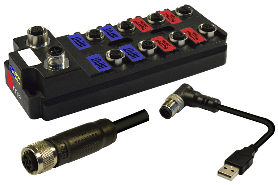
The IP67 SMART JUNCTION BOX WITH INTEGRATED PLC from HTP, Italy is not only a 20-channel IP67 IOBOX, but also has an internal Taskscript Runtime, allowing it to have its own logic.
Port
Here is the section that describes each Port.
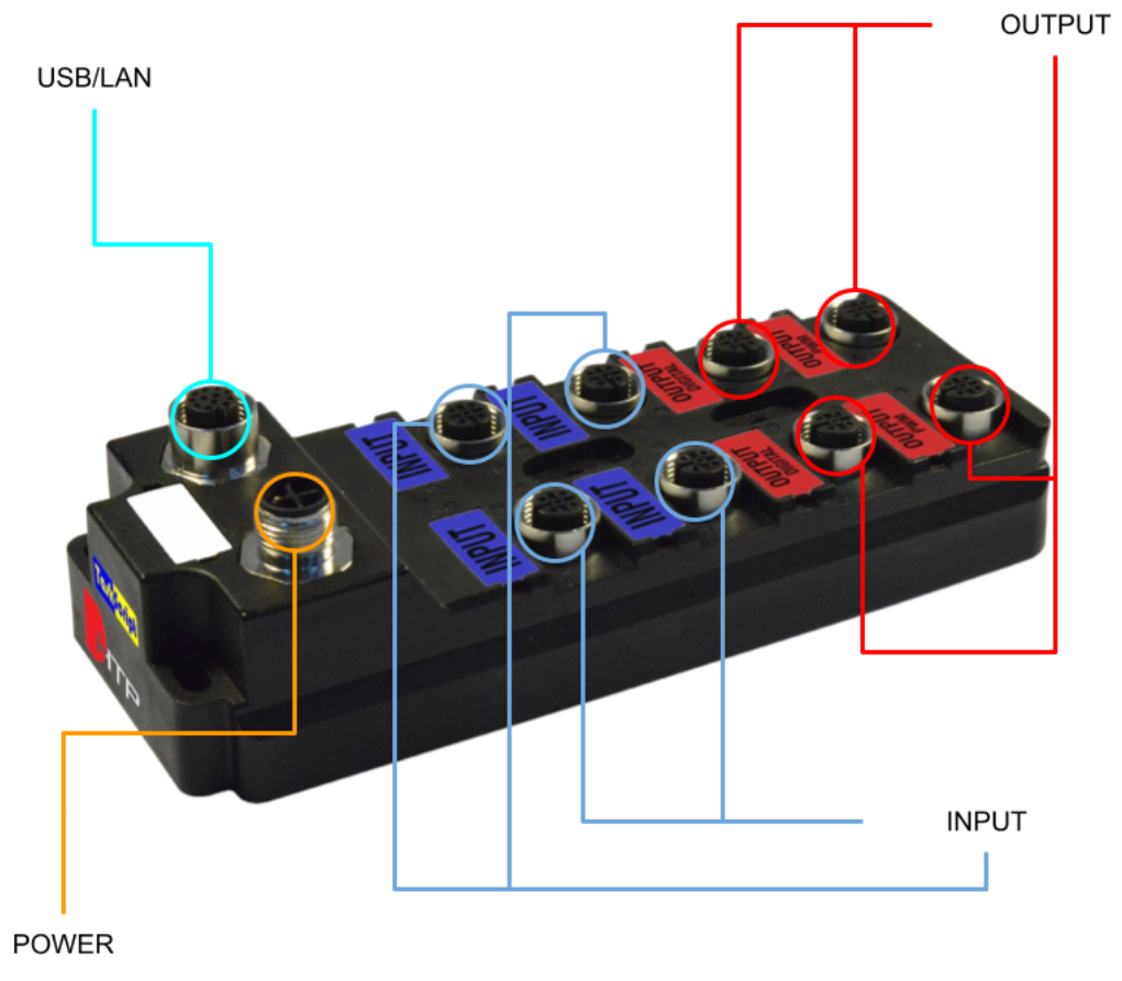
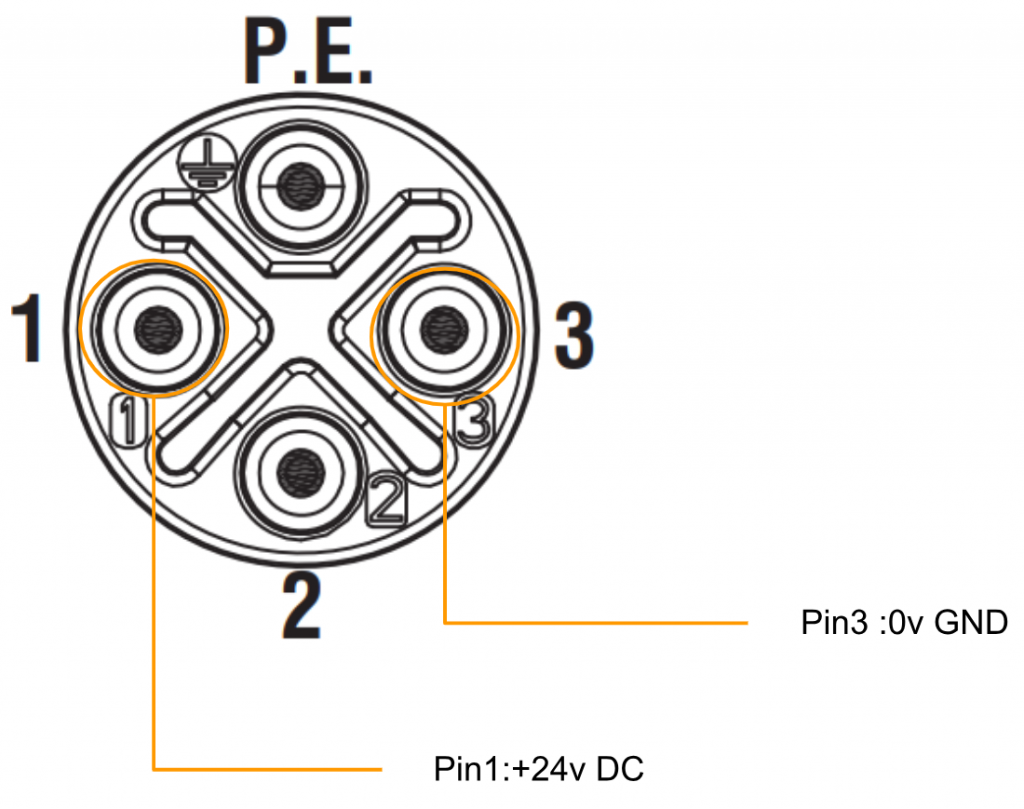
Power Supply
M12 S-Code 4 Poles are used for Power supply’s port.
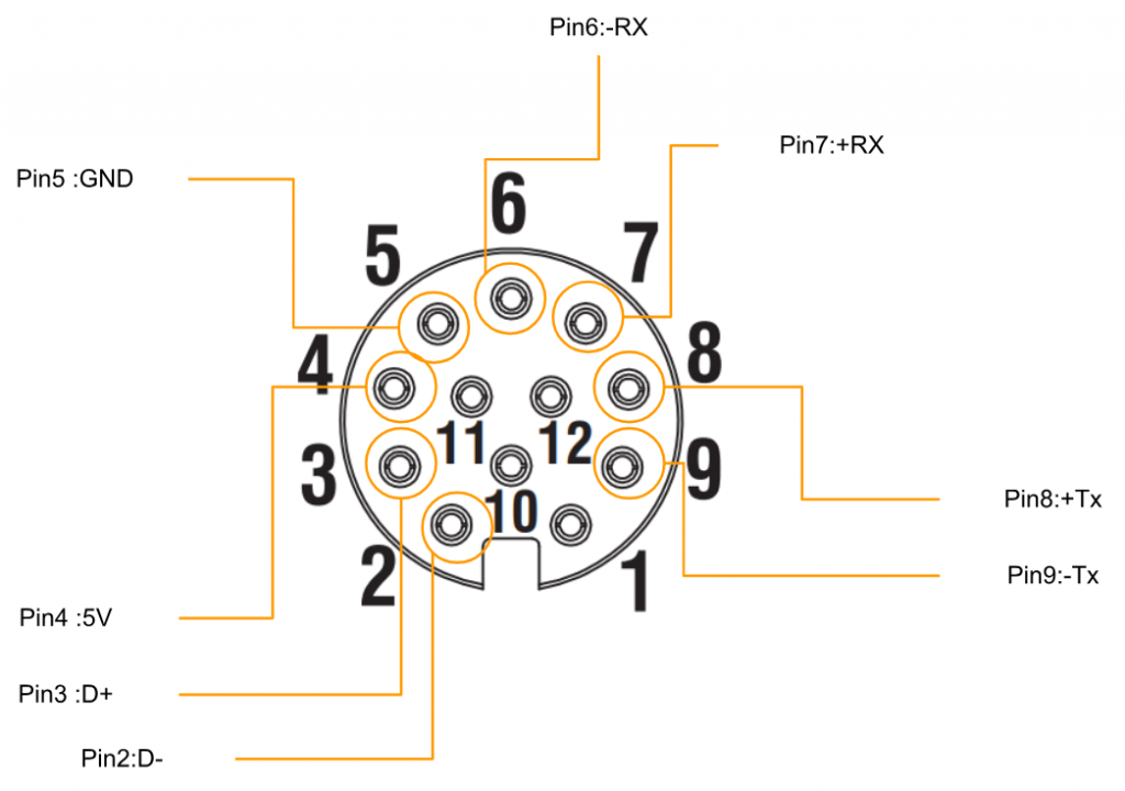
PCD
This Port is a LAN Port for communication between the PC and the device or between devices.M12 A-CODE 12 Poles are used.
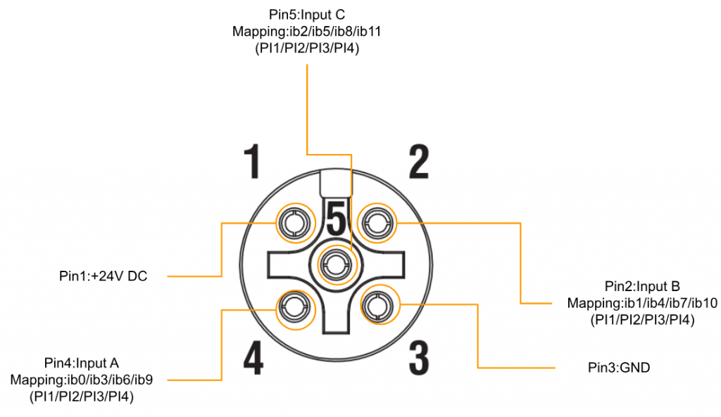
INPUT
M12 A-CODED Female 5 Poles is used.
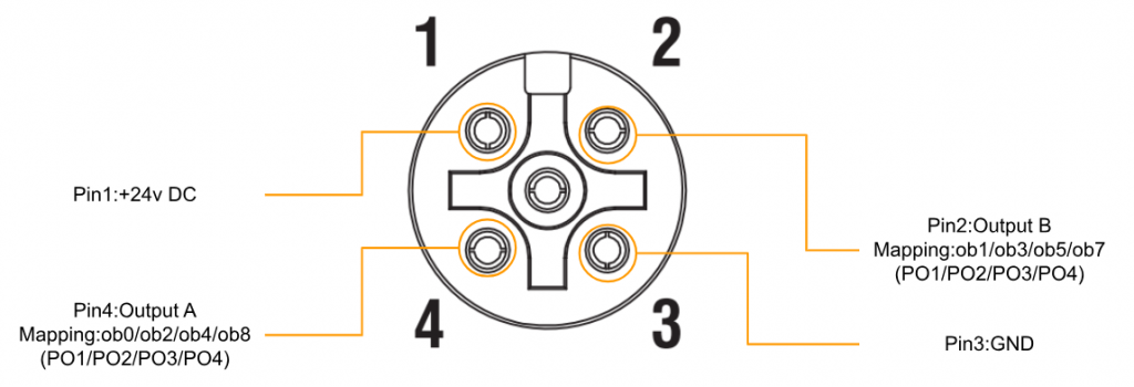
OUPTUT
M12 A-CODED Female 4 Pole is used.
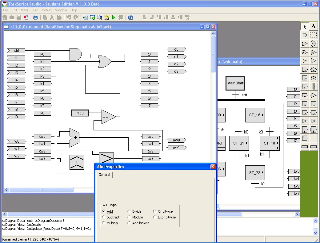
TaskScript?
TaskScript is a technology for the development of embedded systems that allows designers to work only at the graphic level, following a model-based approach.
These two are the main technical components that embody the TaskScript development methodology:
- TaskScript Studio IDE (Integrated development Environment), a graphical environment supporting the entire development lifecycle
- TaskScript Kernel, a runtime module installed in a microcontroller to support the operation of machine code generated from models by the IDE.
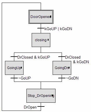
The control flow used by TaskScript Studio is an extension of the State Machine concept to allow parallel processing. Overall, the TaskScript modeling language is similar to two of the five languages proposed in the IEC 61131-3 standard. They are Function Block Diagram and Sequential Function Chart (SFC).
However, the TaskScript modeling language was intentionally designed to accommodate those built on low-performance, low-power CPUs, instead of strictly following the IEC 61131-3 standard.
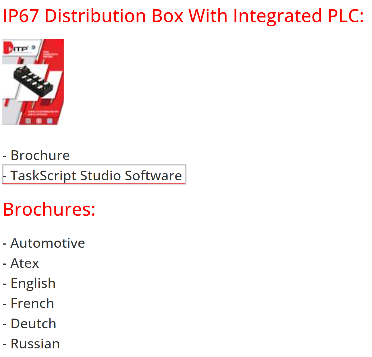
Download
Download TaskScript from the link below.
https://www.webhtp.eu/StaticContent/Detail?permalink=download
An EXE File like this was downloaded.

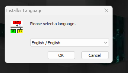
Installation
Double-click on the EXE File, select the language you wish to install>OK to proceed.
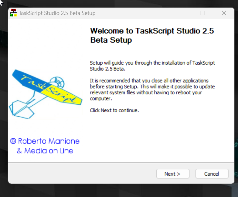
Proceed with Next>.
Agree the license.

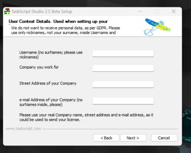
Enter your personal information and click Next> to proceed.
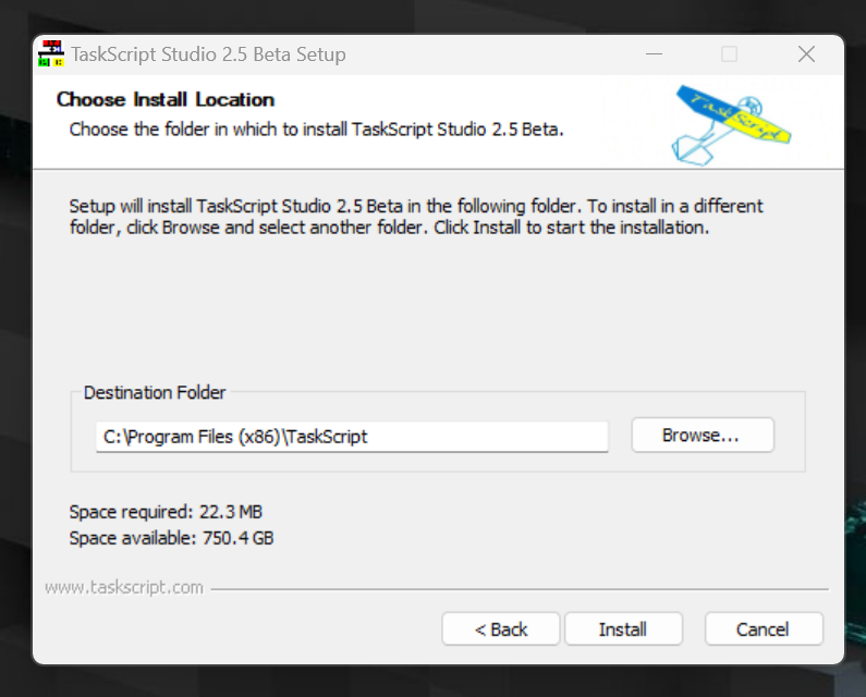
Set the Directory for the installation.
Wait about one minute and the installation is complete!
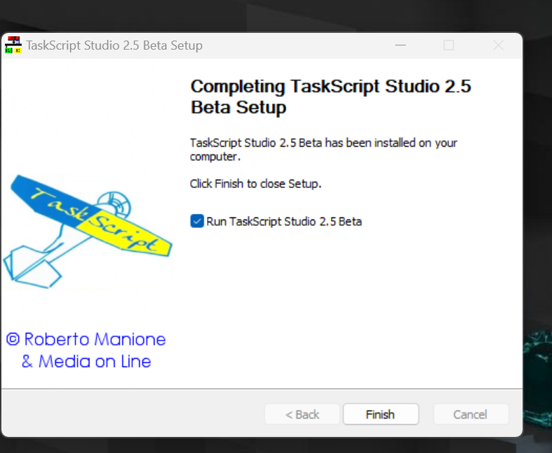
TaskScript is Launched.

Licsense
You need to get a License Key from the place where you purchased HTP’s Junction Box PLC.
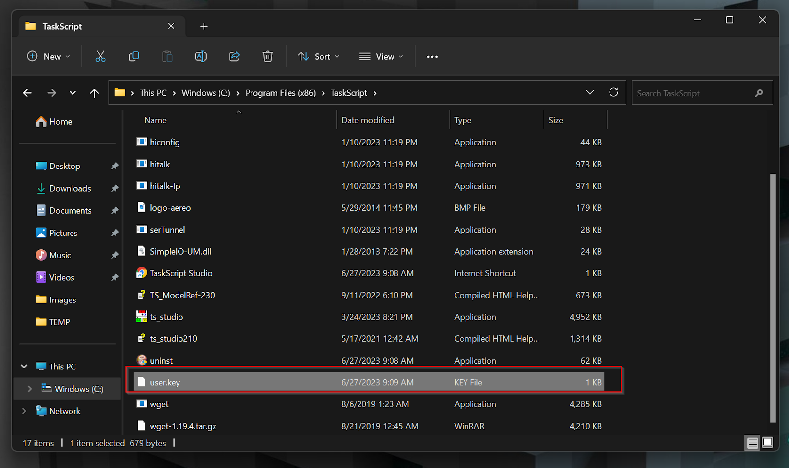
You will receive a File called license.key from the place of purchase.
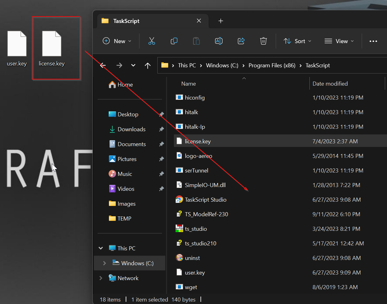
Move license.key to the TaskScript installation Direcotry.
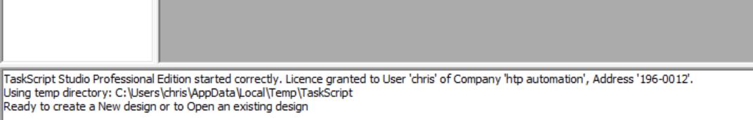
After restarting TaskScript, the license was recognized.
Open Sample Project
In this article, I will download the Sample Project to the HTP Junction BOX PLC and check if the hardware is OK.
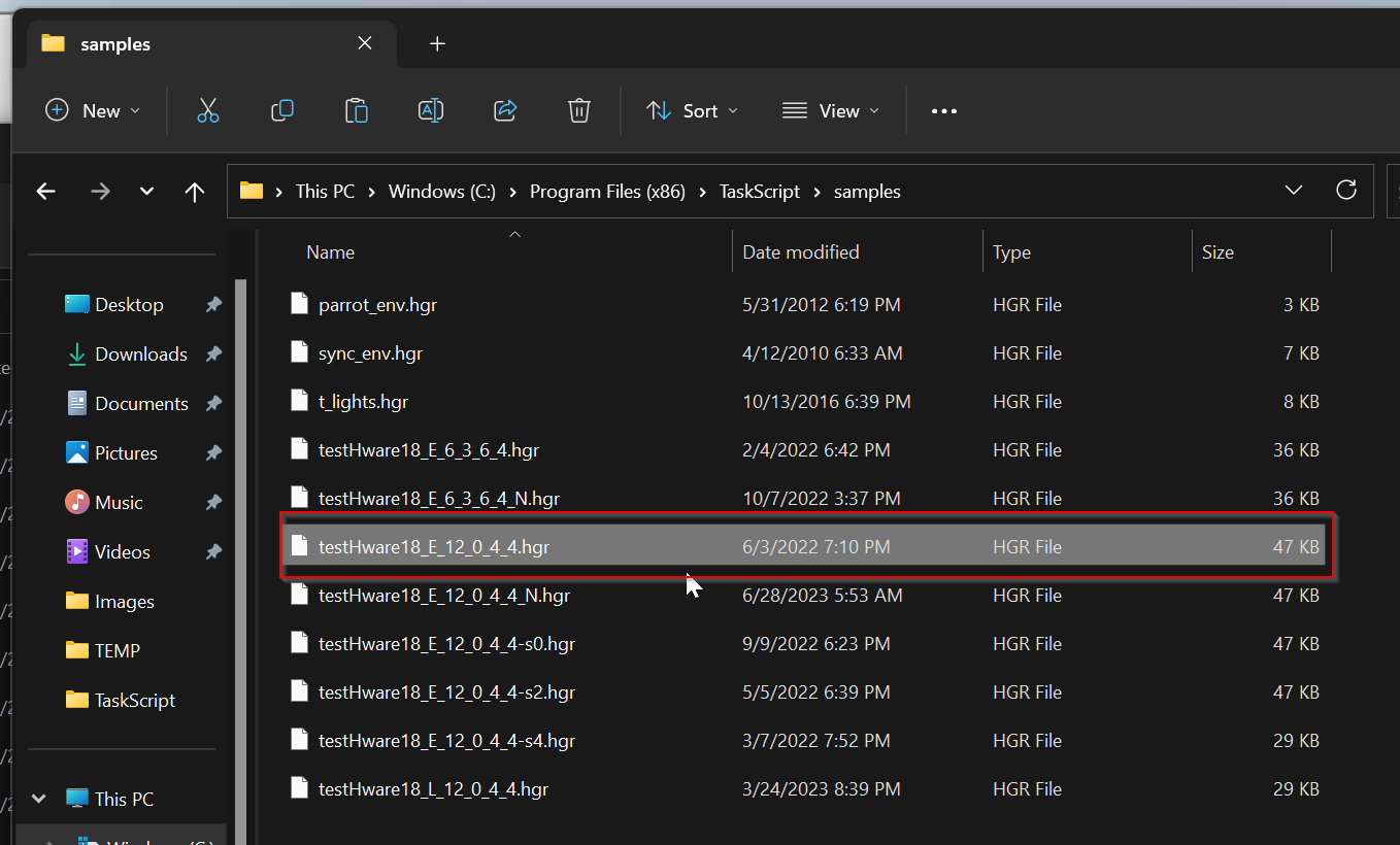
Copy testHWware18_E_12_0_4.hgr from C:\Program Files (x86)\TaskScript\samples} to another Directory.
From TaskScript, go to File>Open and select the Sample project.
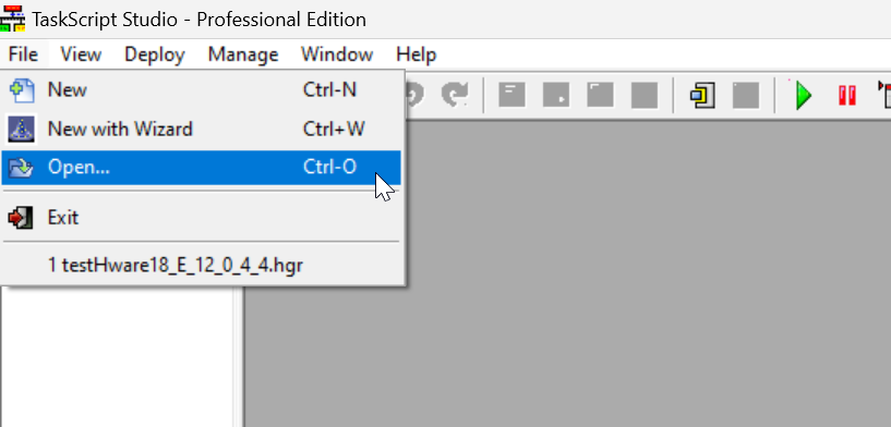
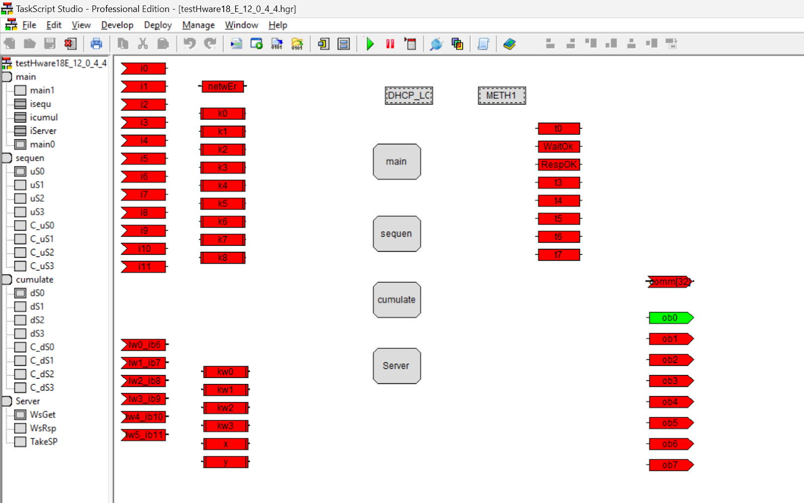
Open the Sample project you just copied.
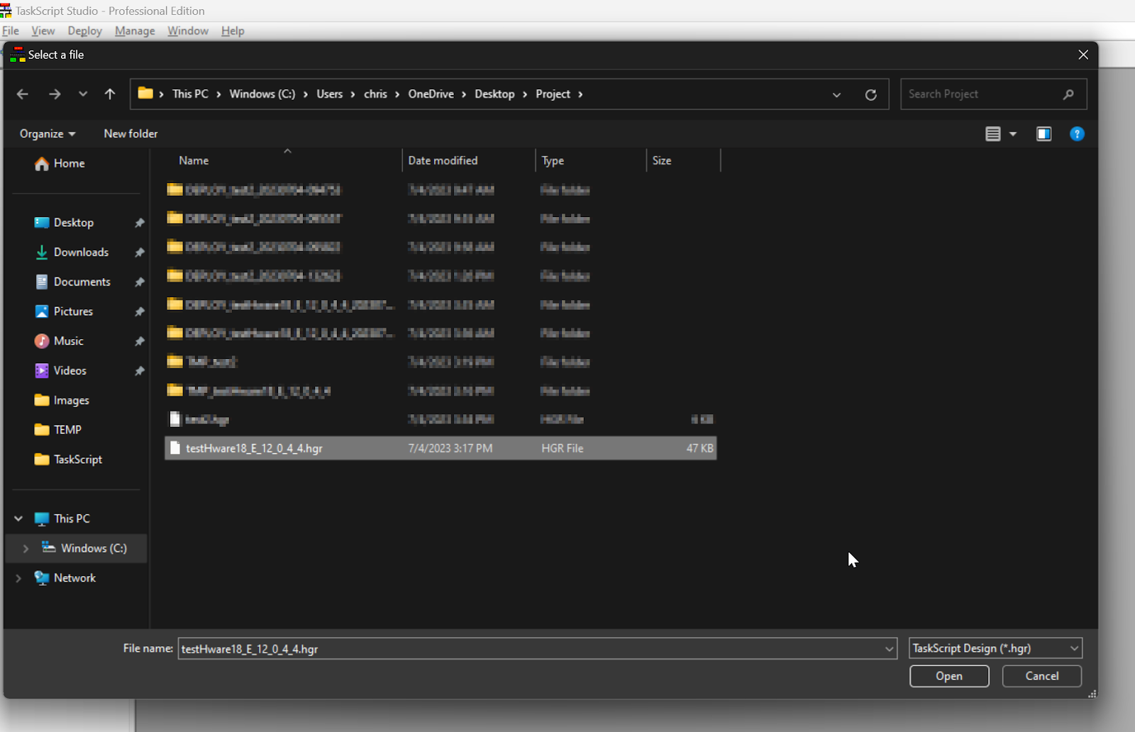
Done!Sample project is opened.

Discovery
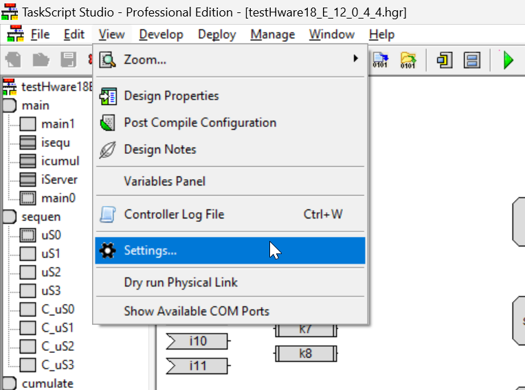
Connect the PC to the LAN Port and USB Port of the HTP Junction BOX PLC and search for the device.Open View>Settings.
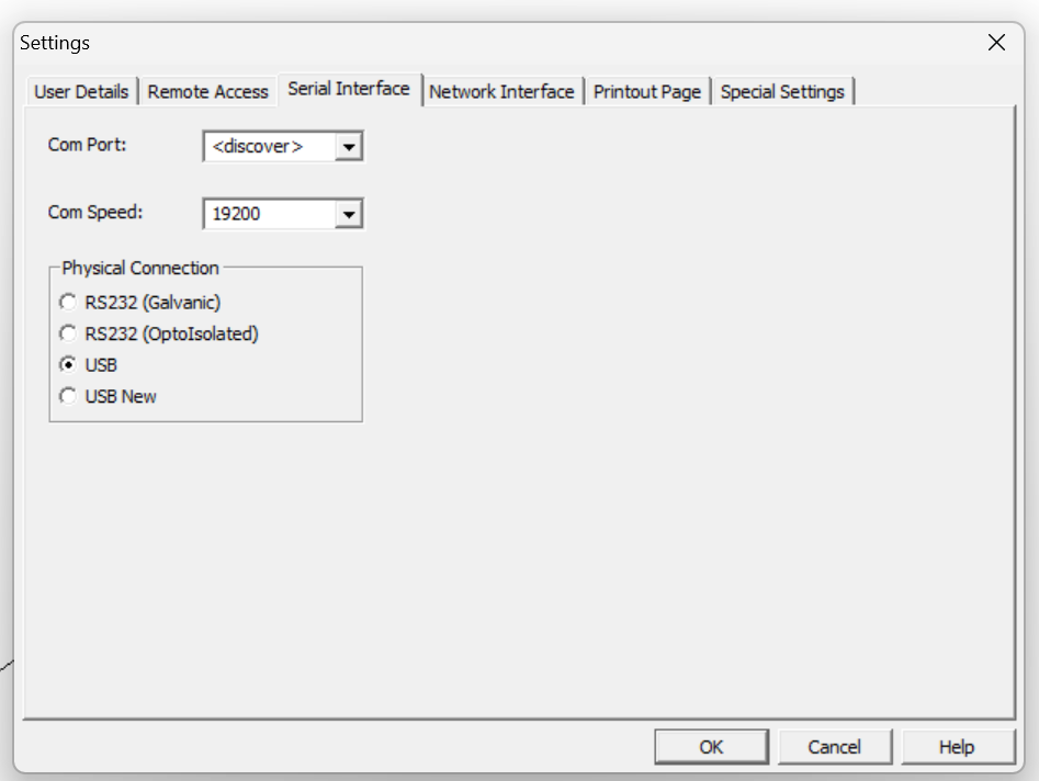
Serial Interface
Open the Tab for Serial Interface and set Com Port to Discover from the Drop List.
Set Com Speed to 19200.
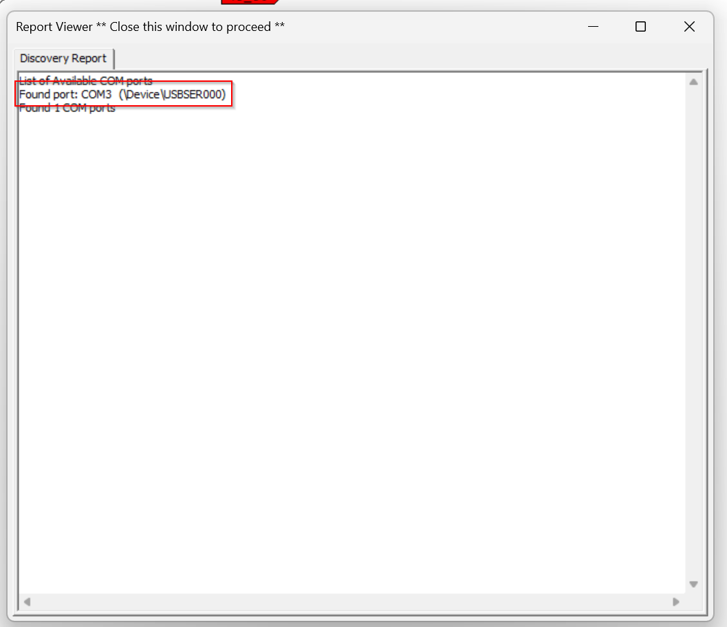
To check if the PC has installed the available COM ports, go to View>Show Available COM Ports.
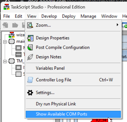
It is OK if the COM number is displayed on the Found port.
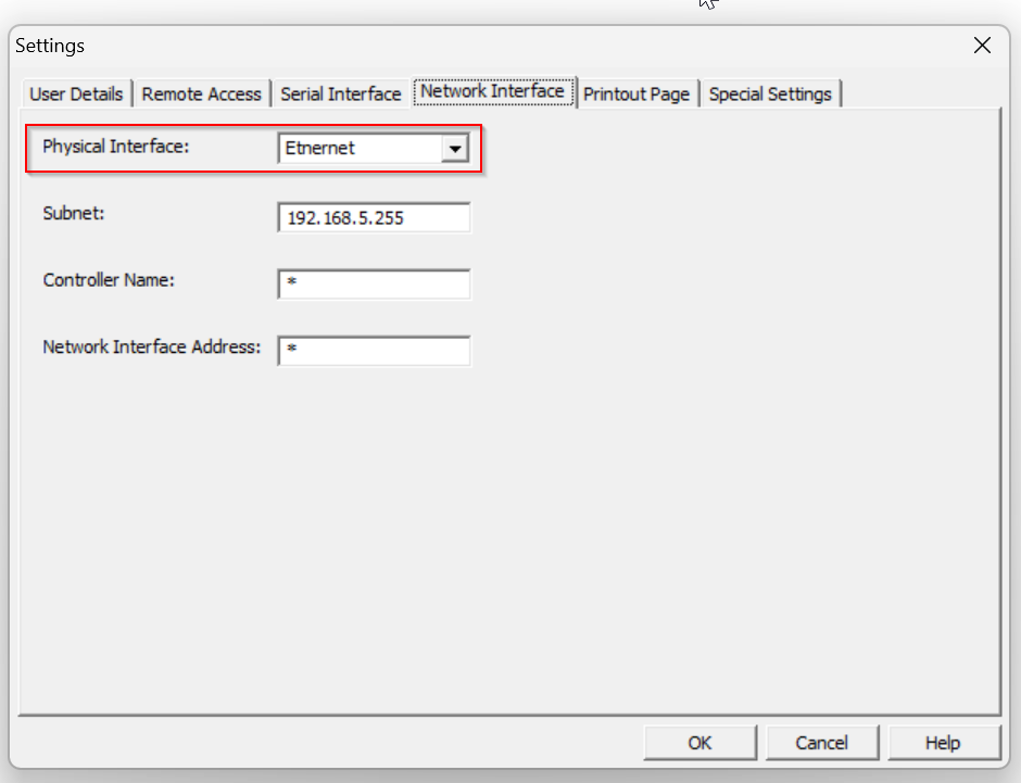
Network Interface
Next, open the Network Interface Tab and set Physical Interface to Ethernet.
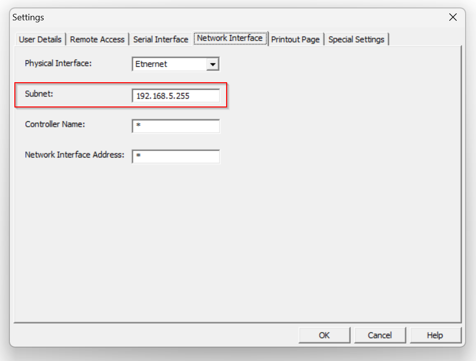
Let’s match with the Network setting to be searched from Subnet.Since I set up my HTP Junction BOX PLC from DHCP Server with an IP of 192.168.5.XXX,
Subnet should be 192.168.5.255.(Default is 192.168.1.64, you can set Subnet to 192.168.1.255)
Discover Controller
Next, let’s search for the HTP Junction BOX PLC in the network.
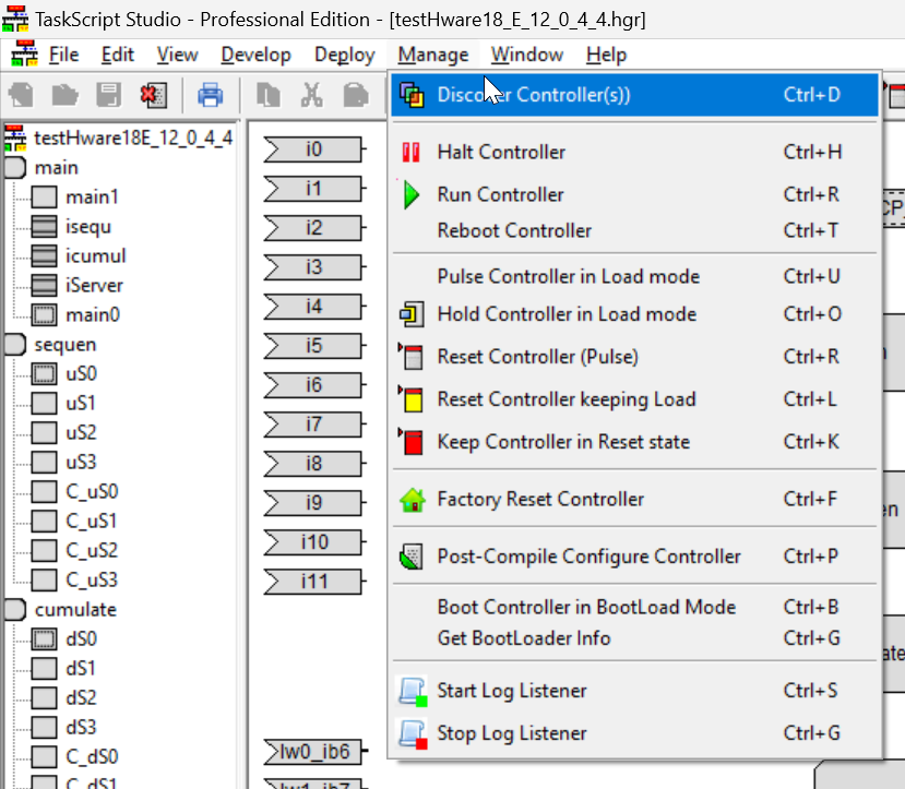
Go to Manage>Discover Controller.
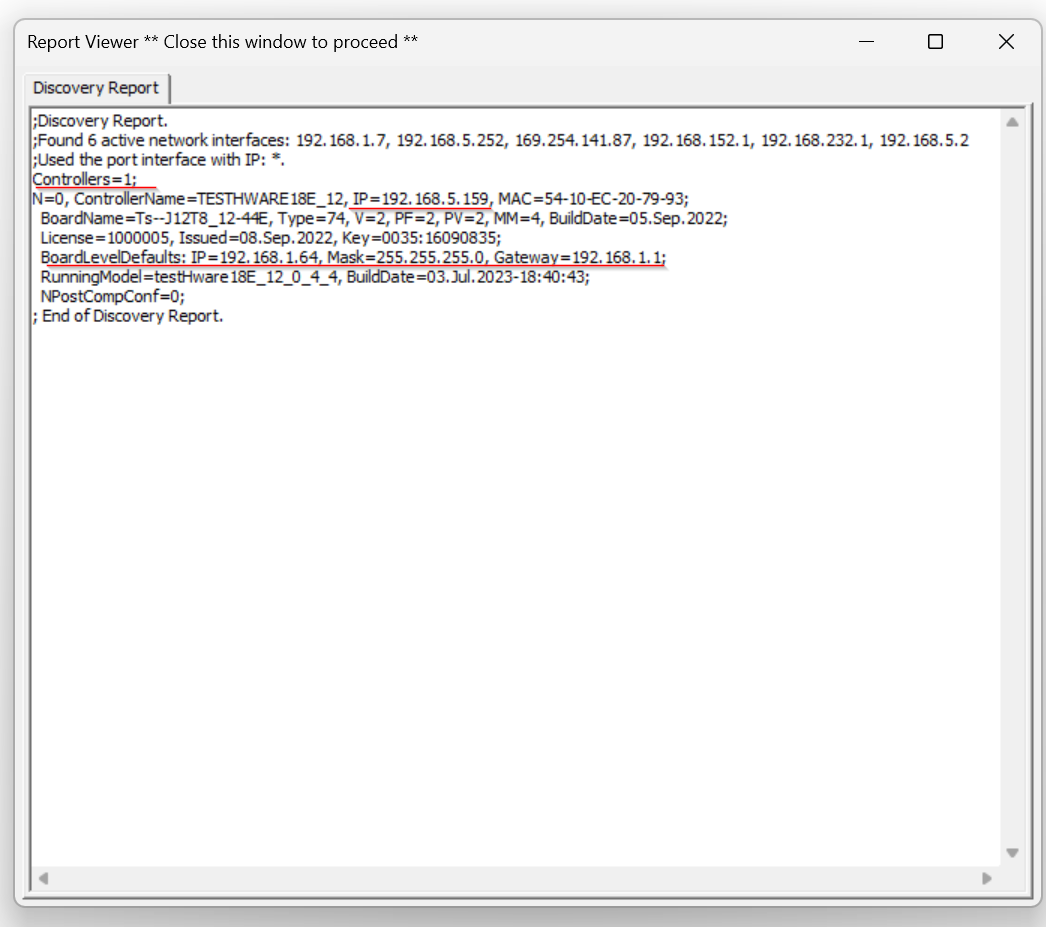
Done!Controllers=1 is one device found, IP is 192.168.5.159.
And the Default IP is 192.168.1.64.
Connect
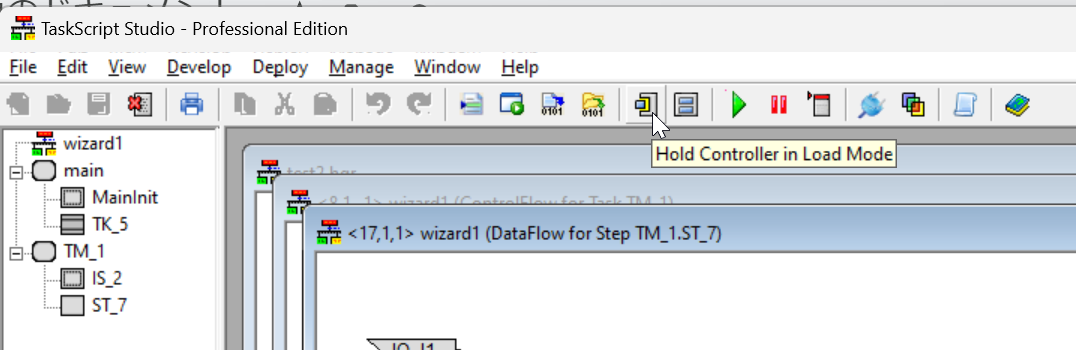
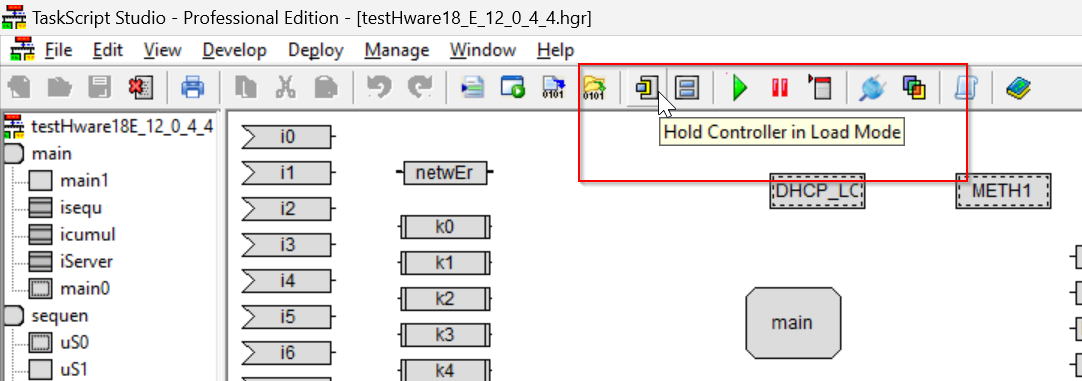
Switch the HTP Junction BOX PLC to Load mode by clicking on “Hold Controller in Load Mode” from the Menu bar.
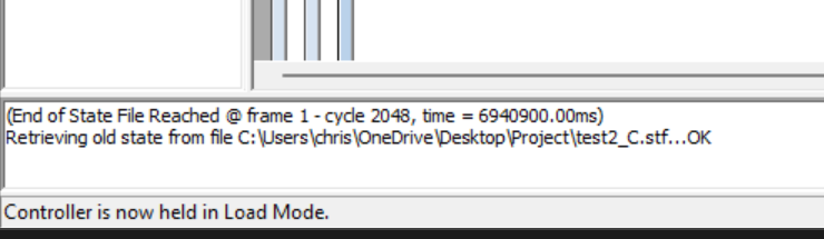
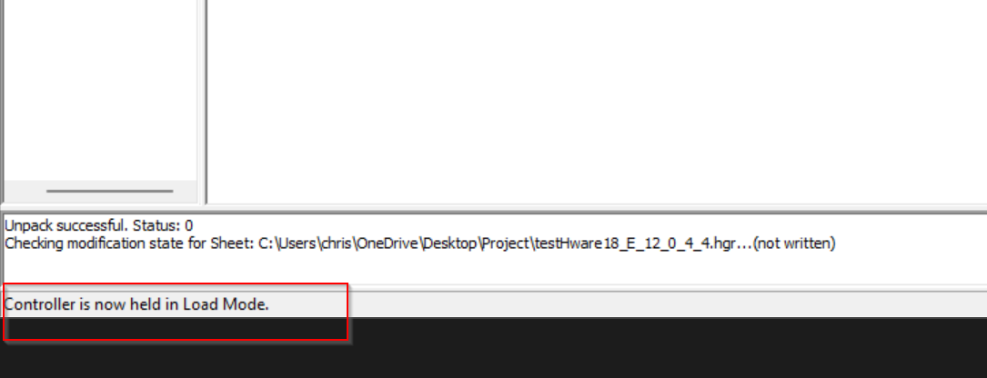
If “Controller is now held in Load Mode” is displayed, it means that the device is now in Load Mode.
Next, connect your PC to the HTP Junction BOX PLC by clicking on Connect to Physical Controller.
OK to proceed.
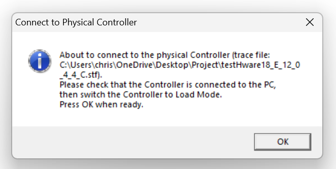
Done!Taskscript is connected to HTP Junction BOX PLC.

Test your Hardware
Finally, we will download the Sample project to the HTP Junction BOX PLC and test the hardware.

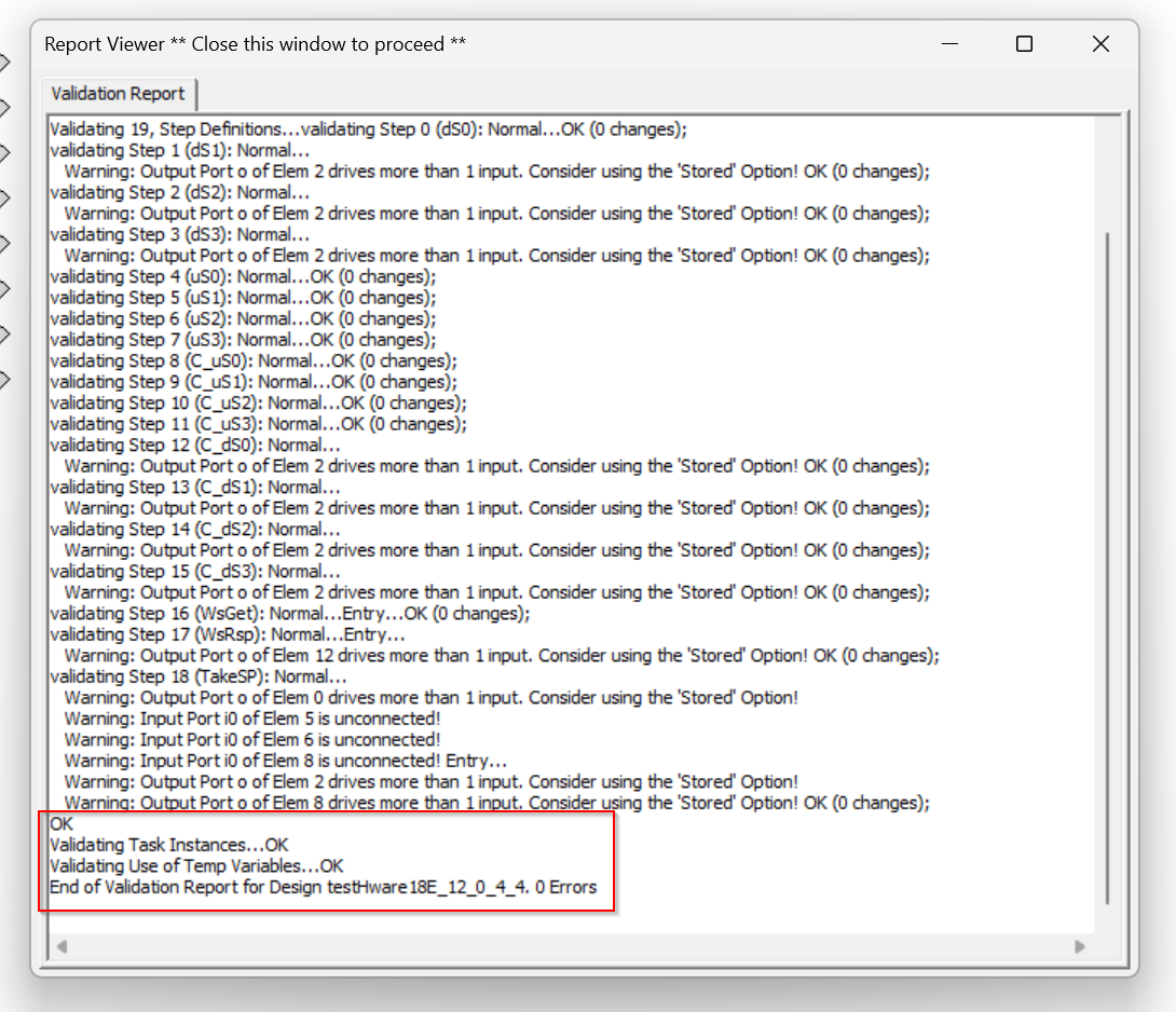
Validate
Click the Validate button to validate the Sample project.

The Taskscript was Feedbacked if the project is OK.
Generate
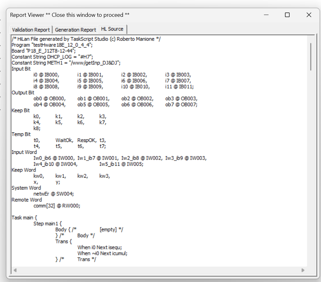
Next, click the Generate button to generate the code.
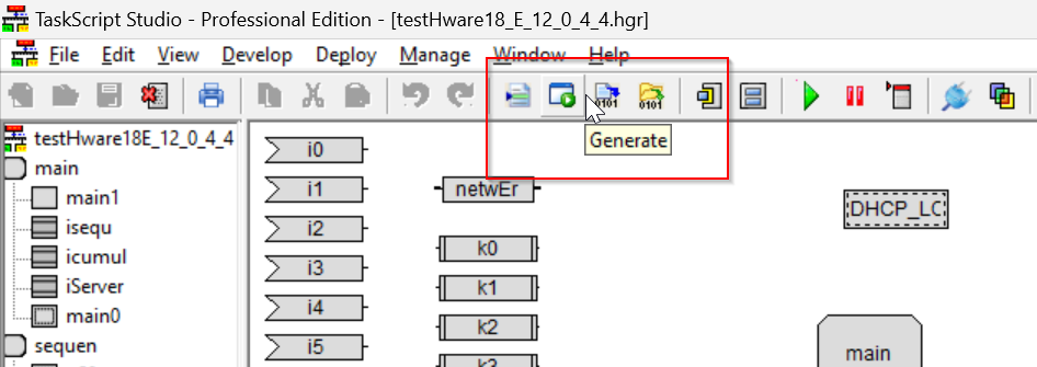
Done!
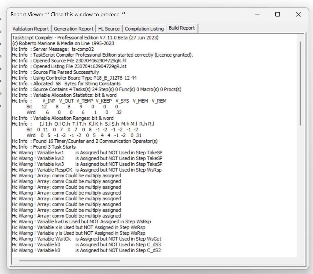
Build
Finally, using the Build button builds the Sample project.

If there is an error, the Background Color of the Report Viewer will turn red.
Hold Mode
To download the project to the HTP Junction BOX PLC, click “Hold Controller in Load Mode” and switch the device to Load Mode.
Download
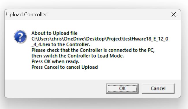
Download the Sample project into the device by going to Deploy>Upload and Run Controller.
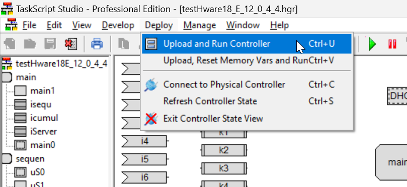
OK to proceed.
Done!
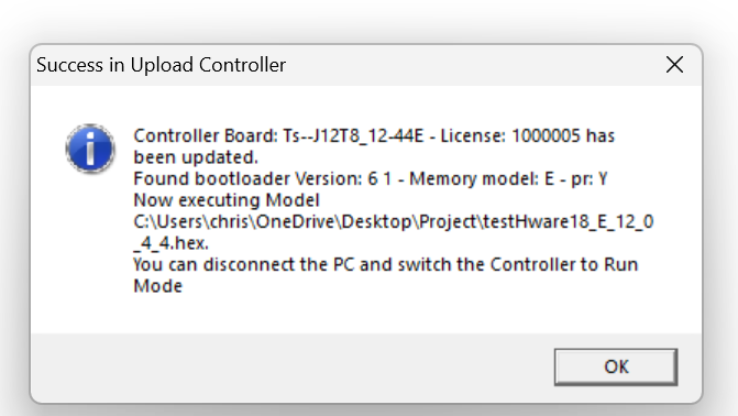
Run
Next, pushing the Run button to switch the HTP Junction BOX PLC to Run Mode.

Done!Your PC is connected to the
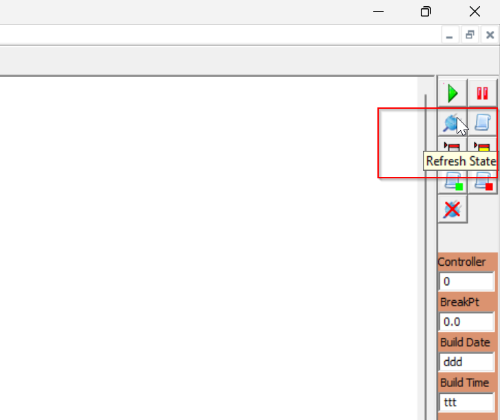
Reflesh
The current Monitor screen can be updated with Refresh State from the Toolbar on the right.
Result
Done!Now you can see that ob0,ob1,ob2… turn on green in sequence and turn off again.
You can see the HTP Junction BOX PLC Sample project ‘s action in this video.
https://youtube.com/shorts/mgFYxzIFSbE?feature=share
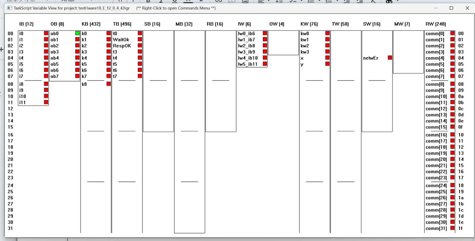
Variables Panel
In fact, you can list project variables from the Variables Panel function.
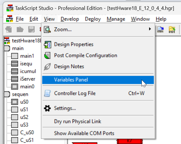
From this screen, not only Input/Output but also internal memory can be checked together.