This is the second episode of the HTP Junction BOX PLC and Taskscript Tutorial. This time, we will create a project from scratch and explain the important parts of Taskscript little by little.
Let’s get started!
Reference Link
Communication Settings
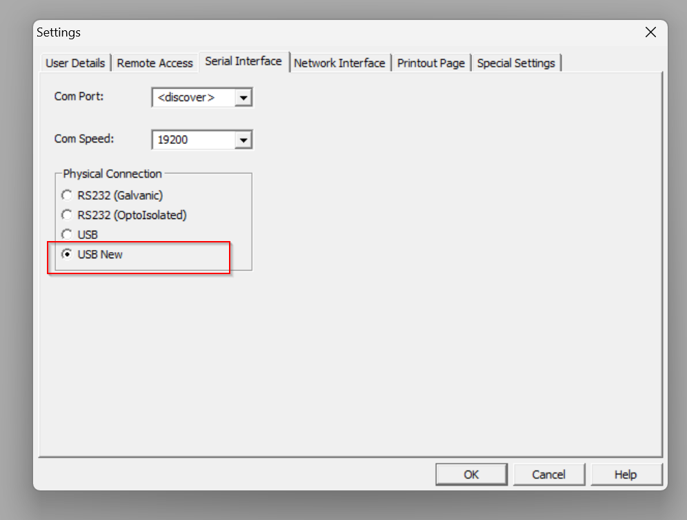
Configure communication settings to connect the PC and PLCBOX.
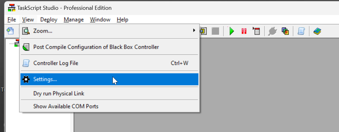
Open View>Settings.
Go to Serial Interface and Select USB New.
Set Subnet to Network Interface.
If your IP is 192.168.5.x, set Subnet to 192.168.5.255.

Search for PLCBOX with the Discover Controllers button.

Done!PLCBOX found.

Enter the IP of the PLC BOX from the Browser to see information on the corresponding PLCBOX.

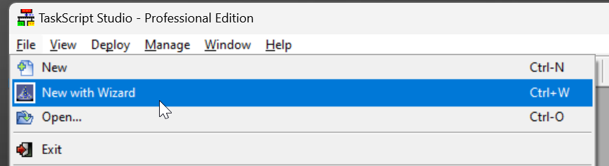
Create Project with Wizard
In the previous example, we used a Sample project, but this time we will create a new project from scratch: Go to File>New with Wizard or Ctrl+w to create a new project.
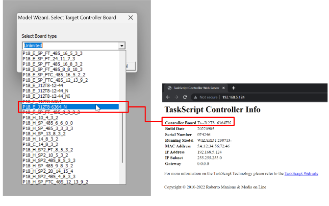
The Board Tpe setup screen appears.
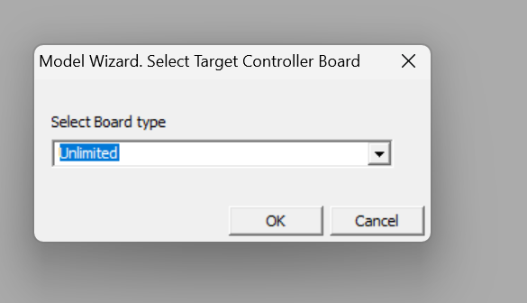
Set the Board Type from the drop-list.

The Board Type to be set can be confirmed from the web screen mentioned earlier.
Done!
Configure the IOs
Change the IO name so that each point of input/output is easily recognizable.
The figure below shows the ICON for inputs and outputs.
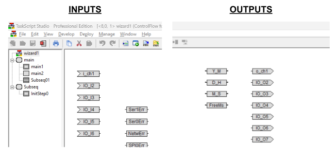
Next, let’s rename input Channel 0.
Double-click IO_I1.
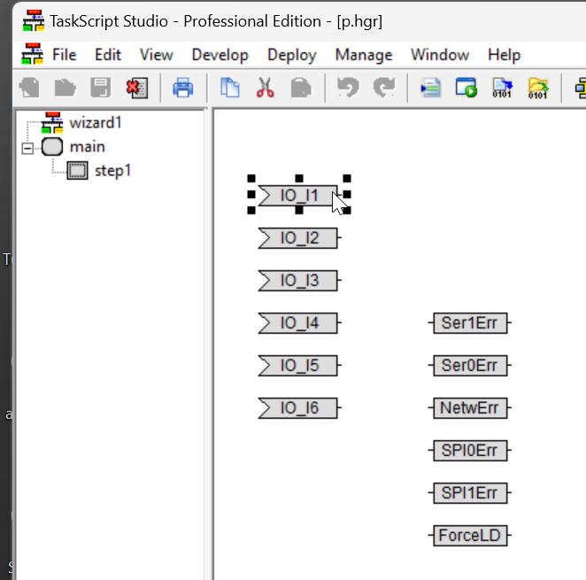
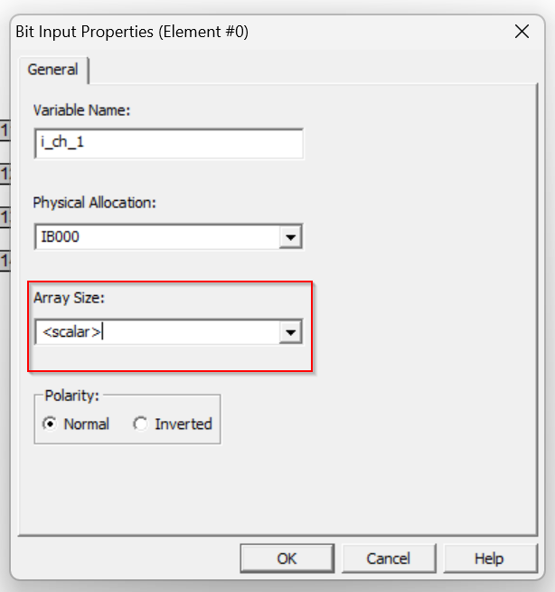
The Bit Input settings screen appears.

Variable Name
You can rename the corresponding variable in the Variable Name field.
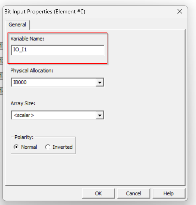
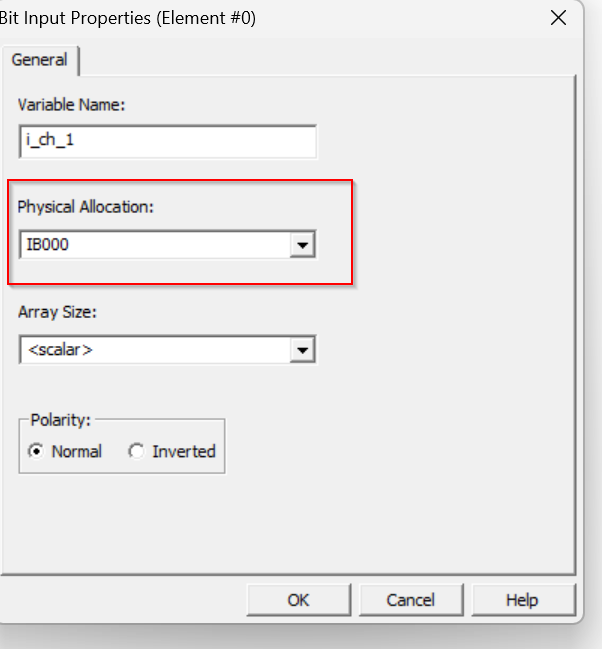
We will change to i_ch_1.

Physical Allocation
Here you can set the Hardware address to be associated with the corresponding Bit Input device.
This is like Mitsubishi’s X0 and X1.
Array Size
Sets the Arra Size for the relevant device, where Scalar is a Single variable.
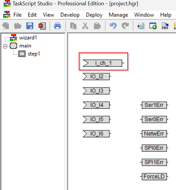
Result
Variable names were changed.
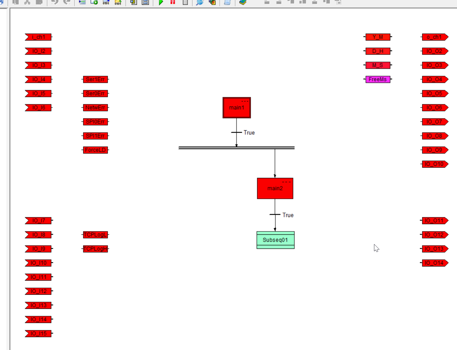
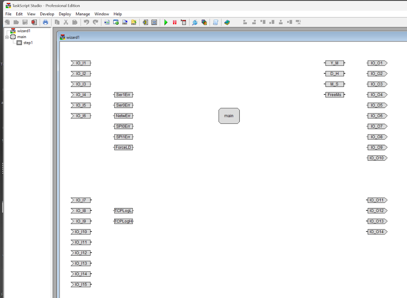
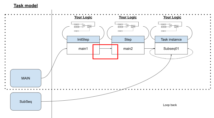
Flow
This is a Flow to be built in TaskScript.
We will not build the logic part in this article, but we will explain a few important parts in TaskScript.
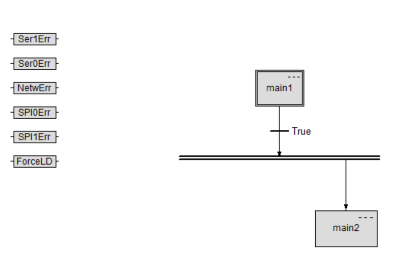
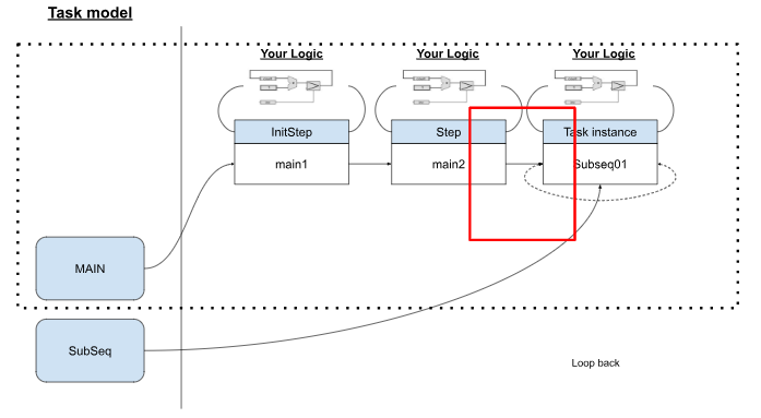
Main Task
The first step is to build the MAIN Task.
Open the Task Editor by right-clicking on the main Task in the Taskscript>Open Task Editor.
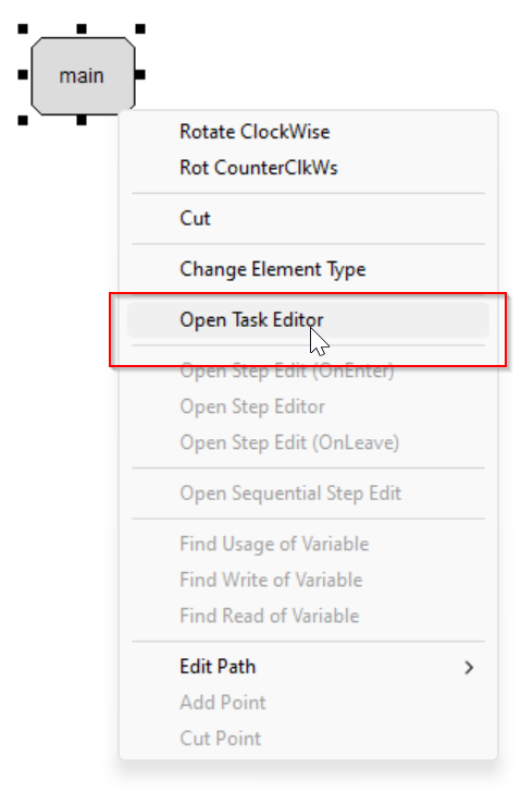
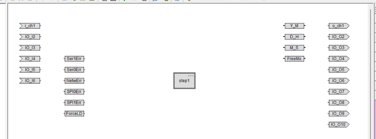
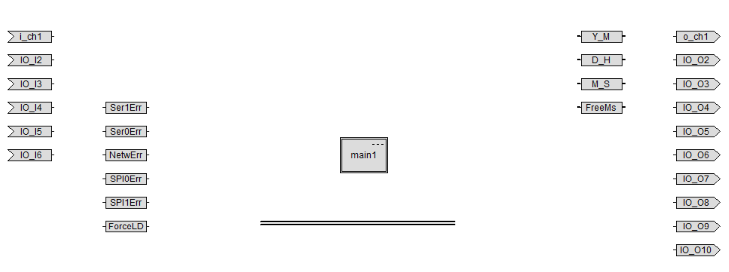
This is the interior of MAIN Task.
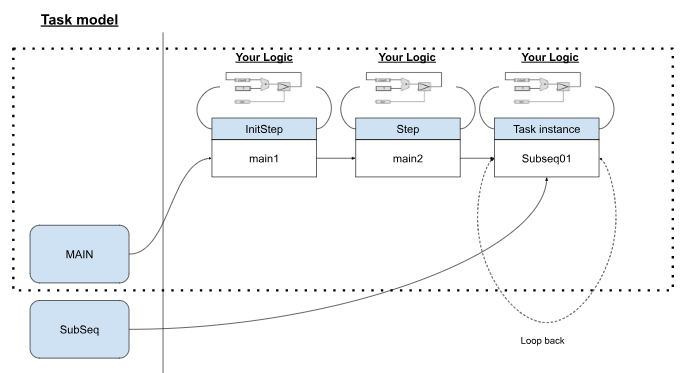
Task?
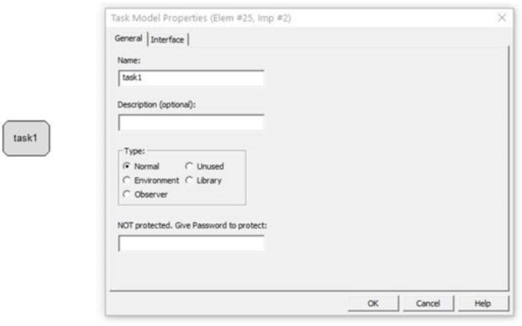
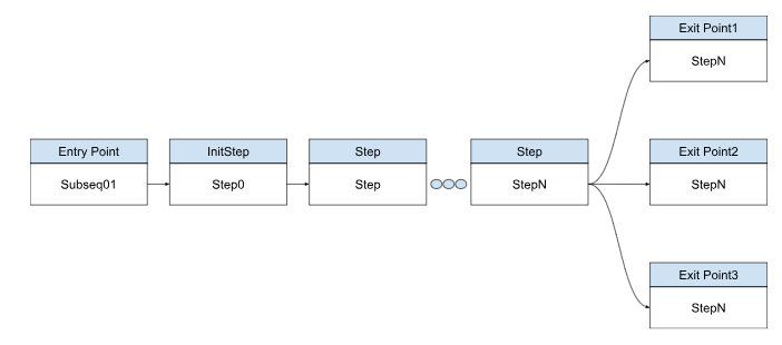
A Task is a component to realize a module of a model. Tasks are there to implement their own logic completion and can be instantiated in a Flow.
Tasks can be defined from the Context Editor, where the Task name, Options, etc. can be set.
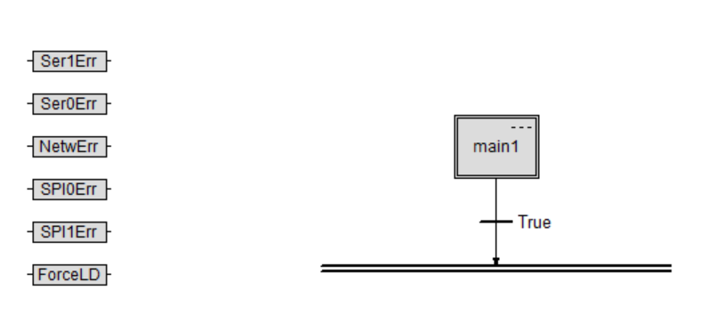
Init Step
The next step is to build the InitStep in the MAIN Task.
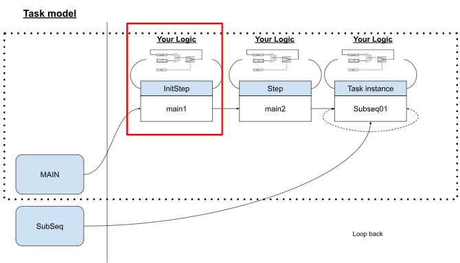
Tasks can be set up with one Entry Point (Initial Step) and in some cases without an Exit Point.
Configure
Double-click on InitStep to display the settings screen.

This time, change Name to main1.
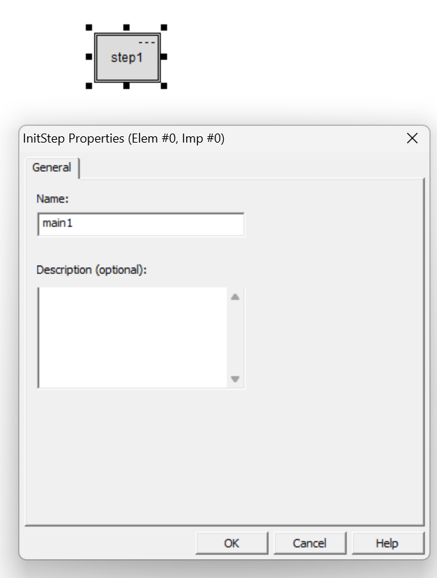
Done!

Update Name
After changing the Step name, click Open task Editor one more time to update the Tree view.

Done!

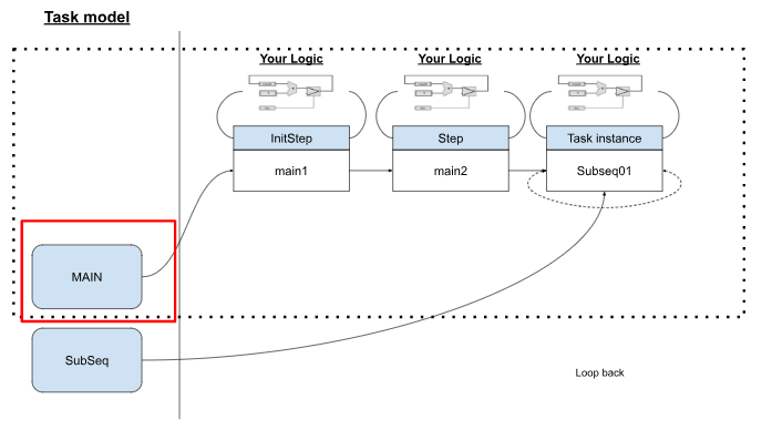
Context Diagram Editor
If you want to see the entire Project Flow, right click on ICON at the top of the Tree>Context Diagram:Your project name.

You can thus return to the overall Flow screen.

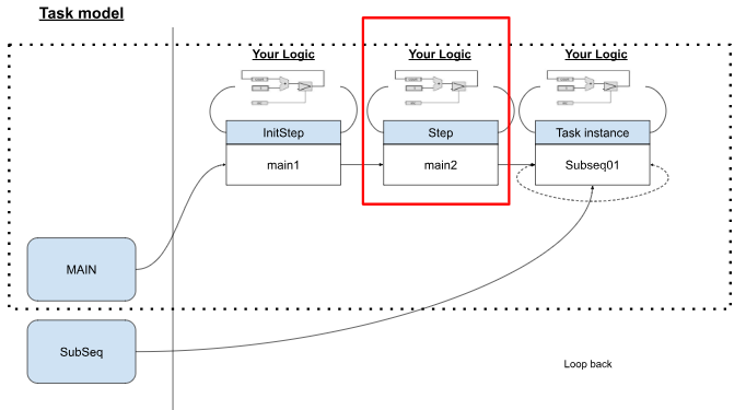
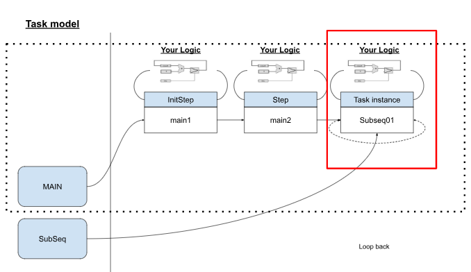
New Task Model
Now we may add a new Task Model (SubSeq in red box).

Switch to the Whole Flow screen using the previous operation.
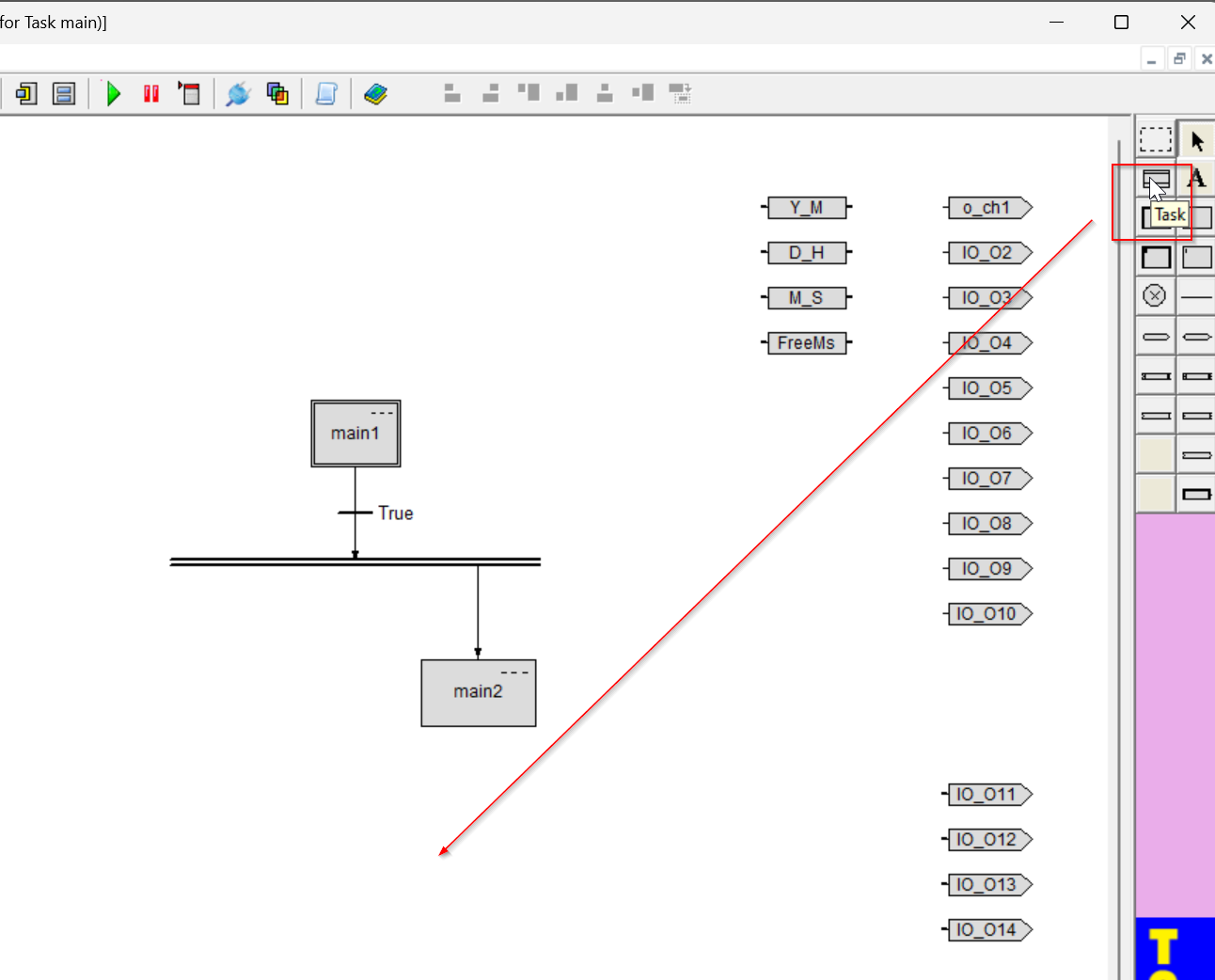
Add a Task Model to the project from the Toolbar on the right.

Done!A new Task Model has been added.

Double-click on Task Model and rename the Task.
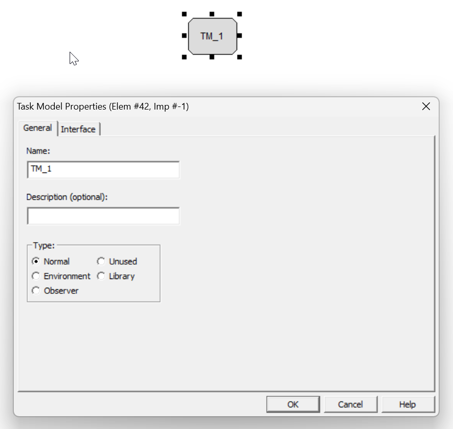
Done!

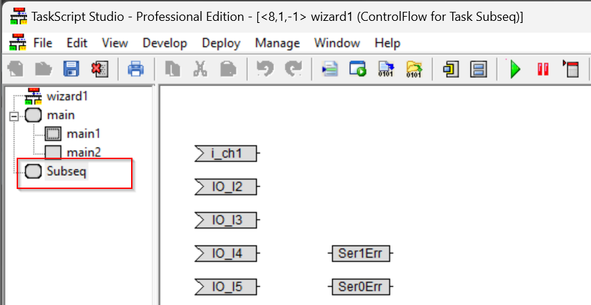
Update View
Once the Task Model name has been changed, select the appropriate Model again > Open task Editor and the Project Tree will be updated.

Done!
Add Parallel
The next step is to create a control that transitions from main1 of InitStep to main2 of Step.
Right click on main>Open Task Editor.

Add a Parallel component from the Toolbar on the right.

Done!
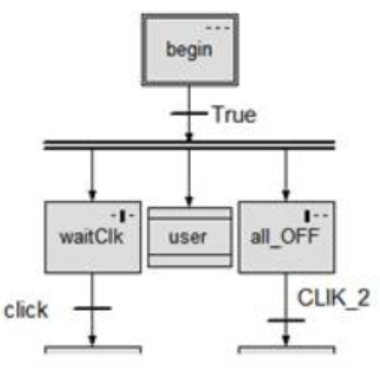
Parallel Fork/Synchronize?
Parallel Fork/Synchronize is used to open and synchronously close two or three parallel computation threads.
As shown in the figure below, three parallel Threads are executed simultaneously.
After the begin InitStep is executed, three Threads (WaitClk, user Task, and all_OFF) are executed at the same time. Note that in this Example, the only transition condition for the begin Step is True, which can be determined from the logic depending on the application.
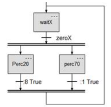
Below is an Example that uses both the top double bar and the bottom double bar synchronizing Threads at the same time. That is, both Step perc20 and Step perc70 are enabled, and then return to waitX Step when execution is complete.
Align
TaskScript can align multiple parts. In the figure below, by selecting multiple InitStep and Parallel parts with Ctrl > Align horizontally, two parts can be aligned in the middle.
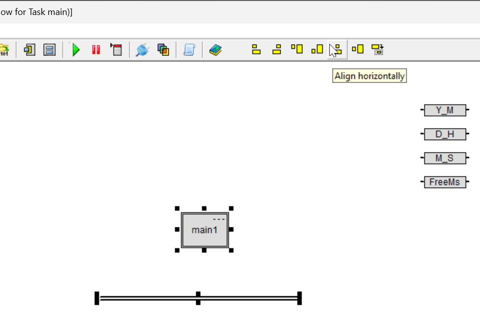
Done!

Arrange Flow
To set up a transition to a Parallel part after the InitStep is completed, it is OK to move to the Parallel part while right-clicking on the InitStep.

The operation is as shown in the figure below.

Done!
Add Step
Now we build Step main2, which is the next step after InitStep.
Add the Step component in the Toolbar on the right.
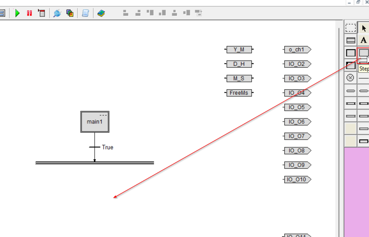
The operation is as shown in the figure below.

Done!

Connect Step main2 and Parallel using the same operation as before.
Add Task Instance
The last step is to configure the SubSeq Task in MAIN Flow.
Add a Task in the Toolbar on the right.
The operation is as shown in the figure below.
Done!

Add Flow Control
Now we need to set up TaskInstance Subseq01 to move to TaskInstance Subseq01 after main2 Step completes execution.
Connect the same parts using the operation just described.

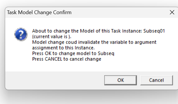
Model Name
Double-click on the Task>Model Name and set SubSeqw from the Drop List.

OK to proceed.
Task instance?
Task Instance allows the functionality of a Task to be used inside the model; in the case of PLC’s IEC61131-3, it should be understood as an Instance of a Function Block. When an instantiated task has arguments, the arguments can also be materialized by connecting them to the necessary variables.
As shown in the figure below, the Task Instance name can be any name, and the Model Name can define any model available in the project.

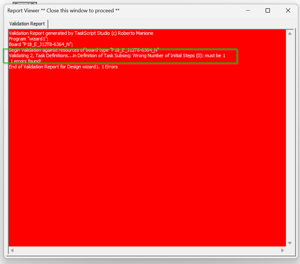
Validate
Now that you have finished creating the project, click the Validate button to Check the project.

A red screen indicates that there is an error in the project.
The error message is that Subseq’s Task does not have an Initial Step.
As explained earlier, an Initial Step is always required in a Task.
Add Init Step
Right click on Subseq>Open task Editor.
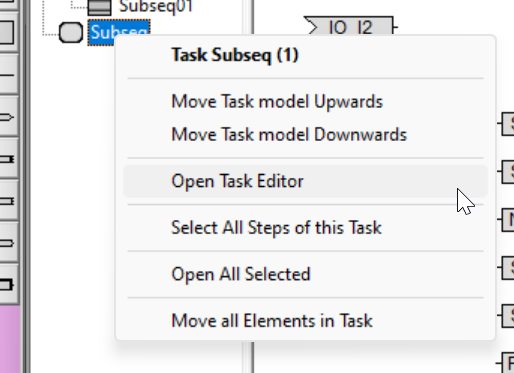
Add the Initial Step in the Toolbar on the right.

Done!

Validate one more time and the error is gone.

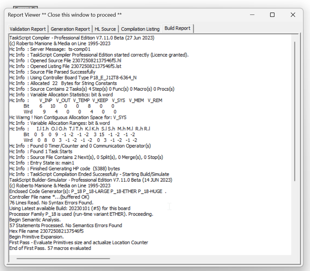
Build
Generates the source code for the project.

Done!
Hold in Load Mode
Switch the PLC Box of the HTP to Load Mode.

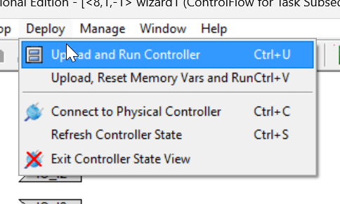
Upload and Run
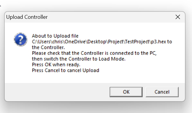
Upload the project to the PLC by going to Deloy>Upload and Run Controller.
OK to proceed.
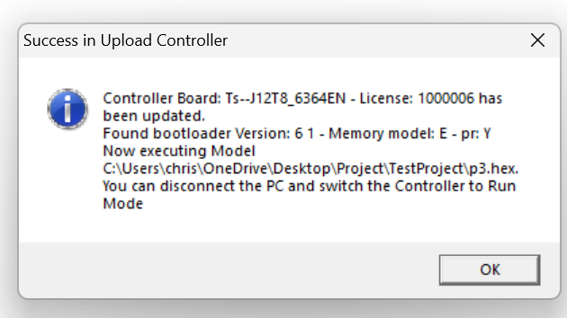
Done!
Connect
Go to Deloy>Connect to Physical Controller to connect the PC to the PLCBOX.

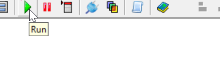
Run
Click the Run button switches the PLC to Run Mode.
Done!It is now green SubSeq01 because Substep01 Task is being executed.