This is the fourth episode of the Tutorial on the HTP Junction BOX PLC and Taskscript. This time, the control is almost the same as in the previous article, but the program is written in a different way.
Instead of outputting each step directly, we will assign a step number to each step and control the necessary outputs by hitting the corresponding step.
Let’s Start!

Reference Link
Implementation
You can download the project from the previous Tutorial at this Link. In this article, we will create from this project.
Define Global Variable
Add the Global variable.

Add Word Keep to your project.
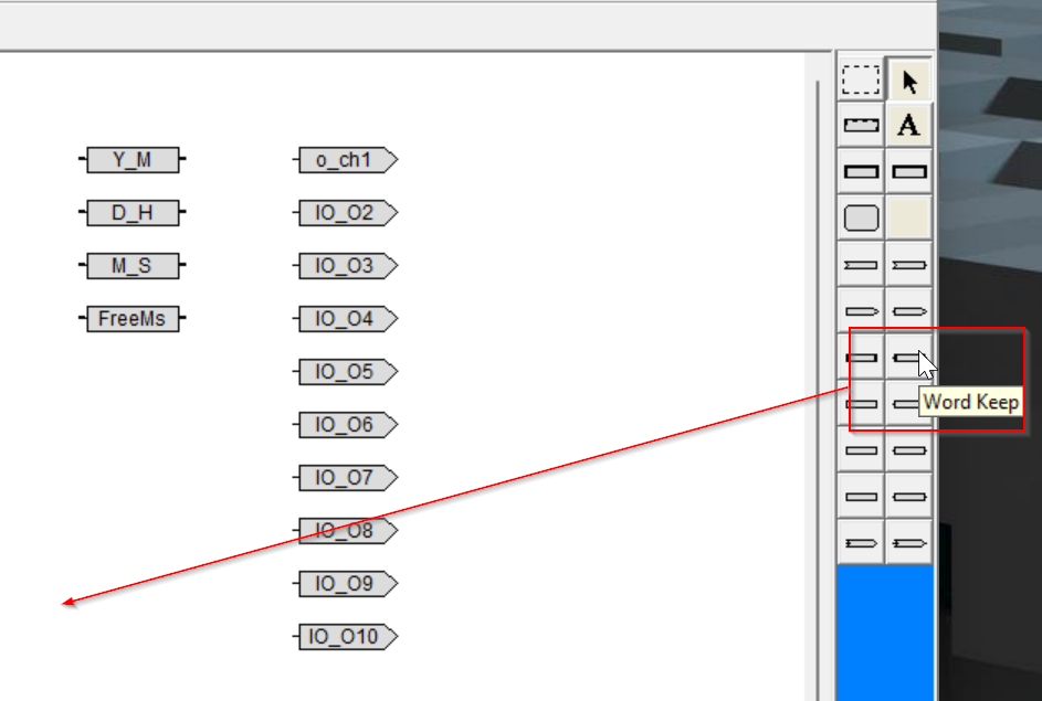
Done!

Double-click to configure the Word Keep component.

Set Variable Name to Subseq1Word.
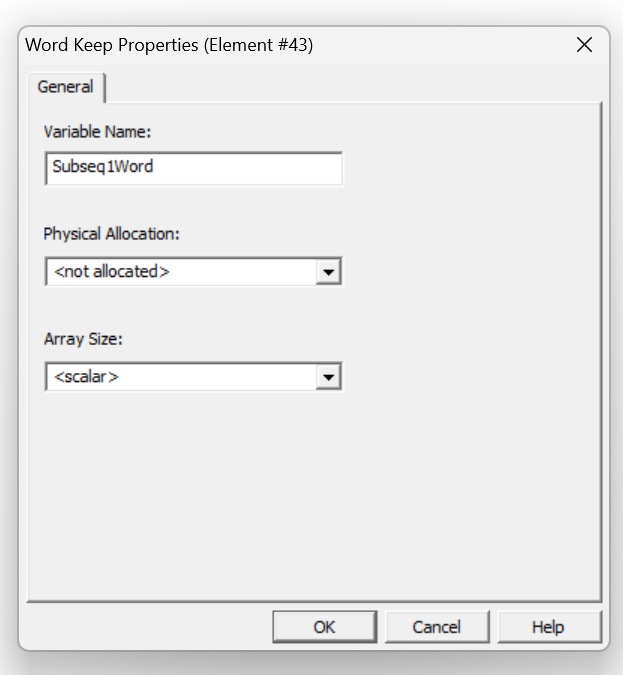
Done!

Edit Subseq
Next, we can edit Subseq.

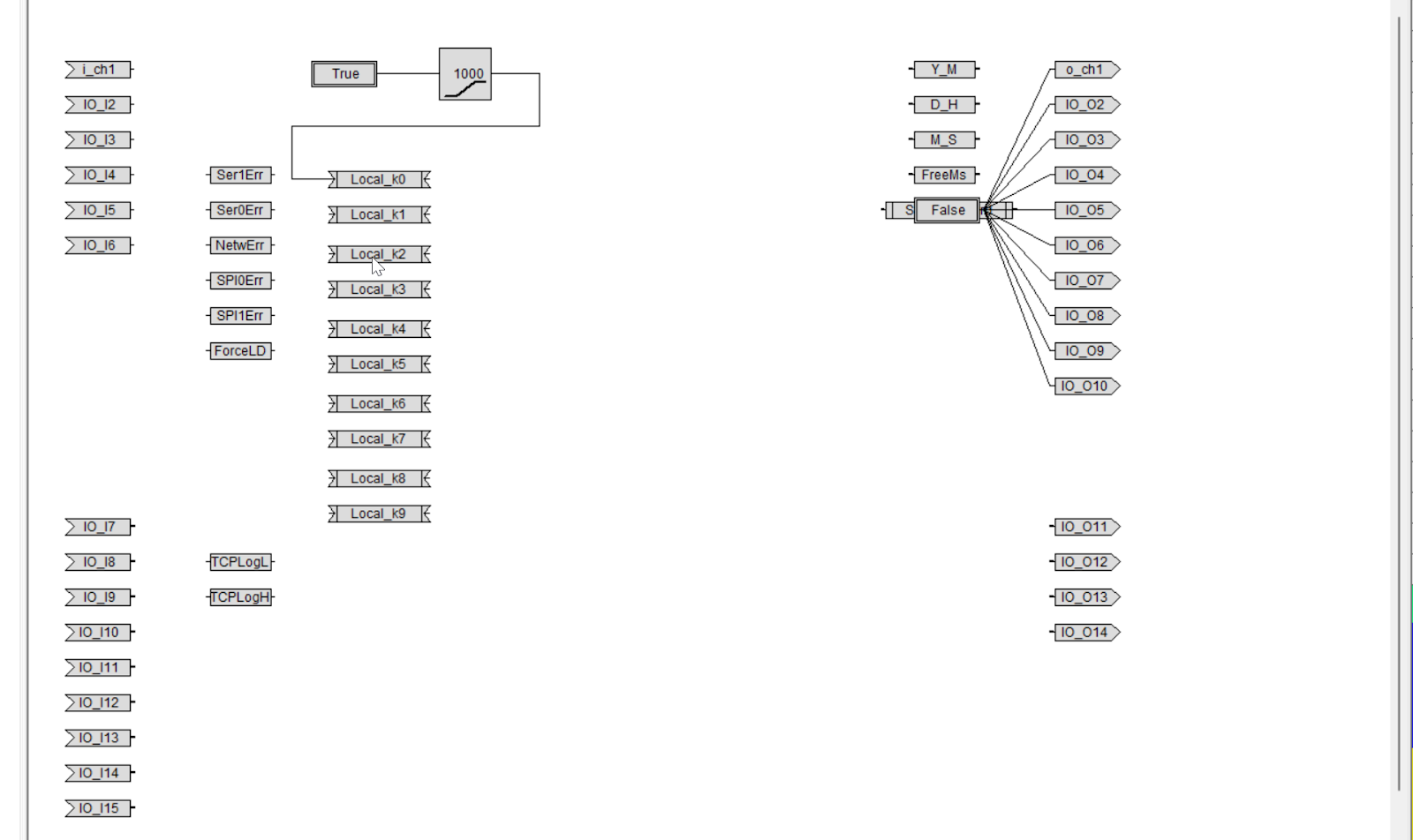
Here is the Flow from the previous Tutorial.

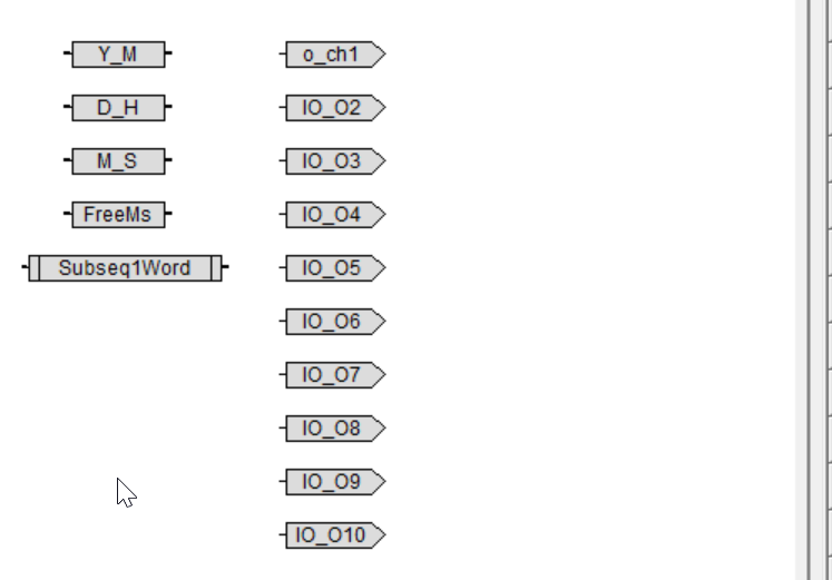
We will now remove the programs that control the output directly within each Step.

This is Step control Program.
Delete the original Action
Delete Output Lines that are directly connected to all outputs with True/False for each Step.
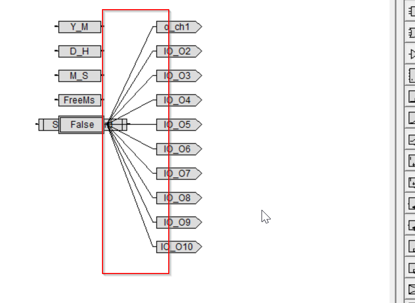
Done!
Assign Values to Global Variable
Instead, it assigns a Step number, such as 0x0 for Step0, 0x1 for Step1, etc. Add a Word Value.
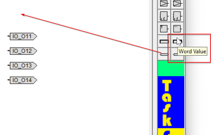
Done!
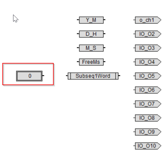
Next, let’s connect with Word Value and Global variables.

Done!

Using Hex Value
If you want to use HEX Value directly, just set it like 0x04.

Insert New Task Model
To add a new Task Model, click on the project name>right click>Open Context Diagram Editor.
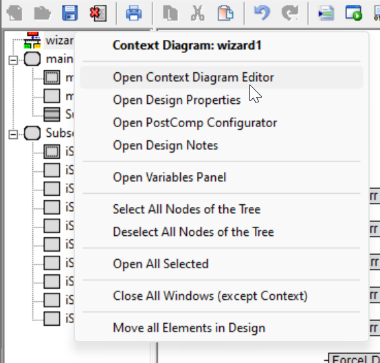
Add a Task Model from the Toolbar on the right.
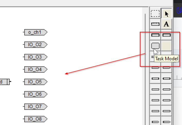
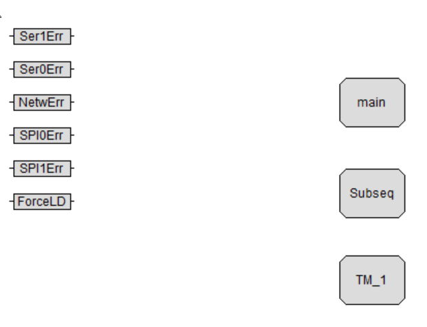
Done! A new ModelTM_1 has been added.
Rename it
Easy-to-understand variable names are fundamental in programming. Let’s name the new Task Model Out_Seq.

Edit the Model
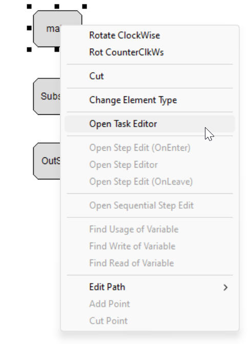
Right-click on the Task Model>Open Task Editor to edit the Task.

Insert Step
Add one InitStep and one Step component as shown below.
Rename it
Change Step for clarity.

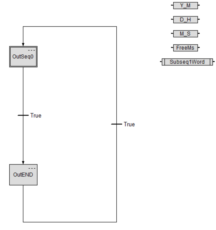
Create Infinite Looping
Create an infinite loop in the Task Model. That is, unconditionally return to OutSeq0>OutEND>OutSeq0 again.
Insert Word Local Keep
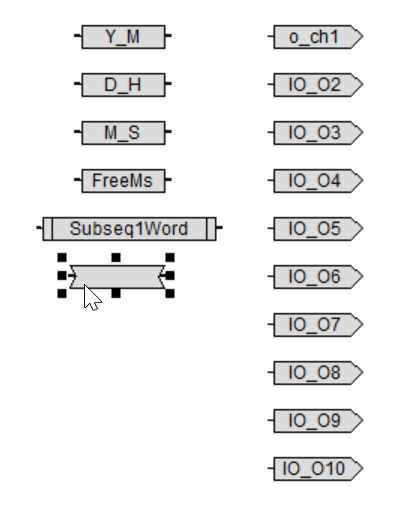
Now add the Local Keep variable again. Let’s add the Word Local Keep component from the Toolbar on the right.
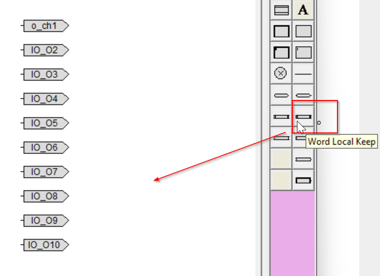
Done!Word Local Keep component added.
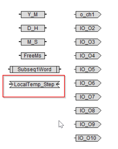
Rename the Word Local Keep variable to LocalTemp_Step.
Insert Bit Local Temp
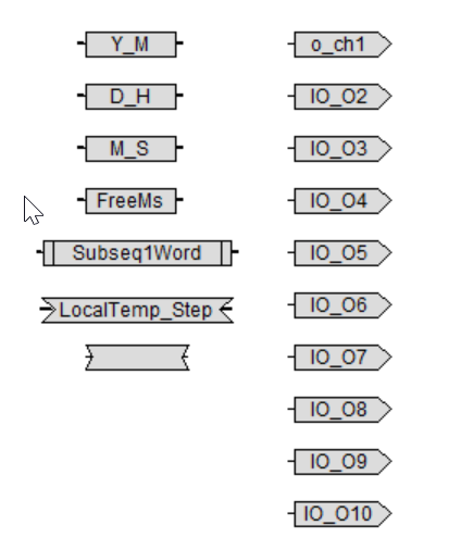
Now add Bit Local Temp to the Task Model from the Toolbar on the right.

Done!
Rename the Bit Local Temp component.

Add six Temp variables as described in Flow.

Edit Step
Select OutEnd>Right click>Open Step Editor.
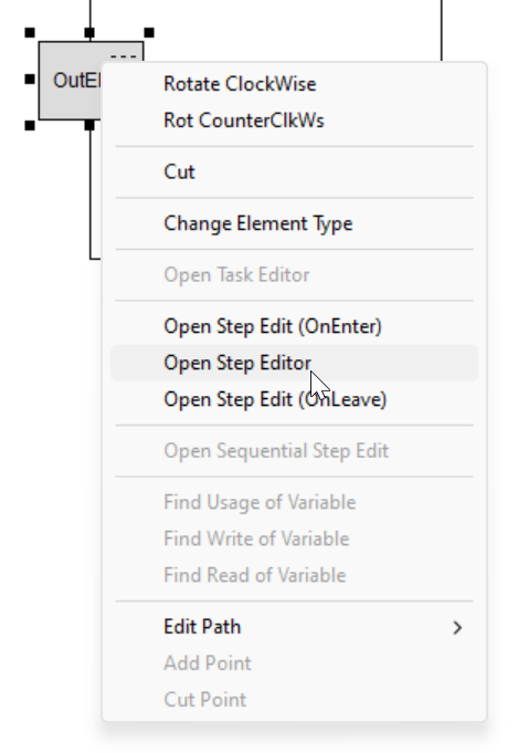
This is the Step to be edited this time.

Assign Value to temp Variables
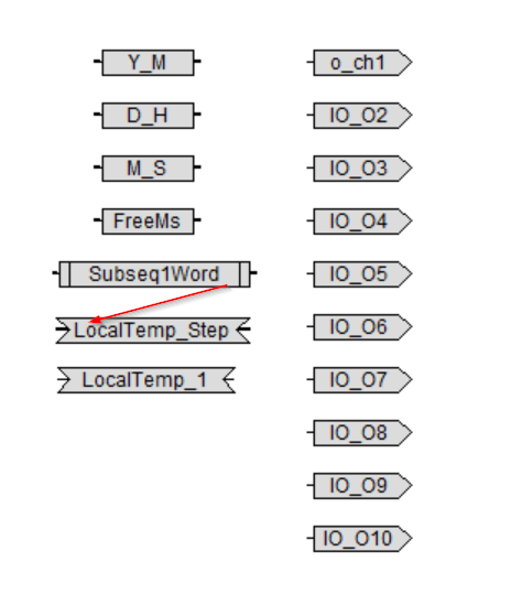
The current value of the Global variable Subseq1Word is stored in the local variable LocalTemp_Step.It is a common action in PLCs to first transfer the necessary variables to another device before executing the control circuit.
Done!
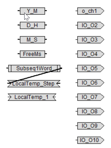
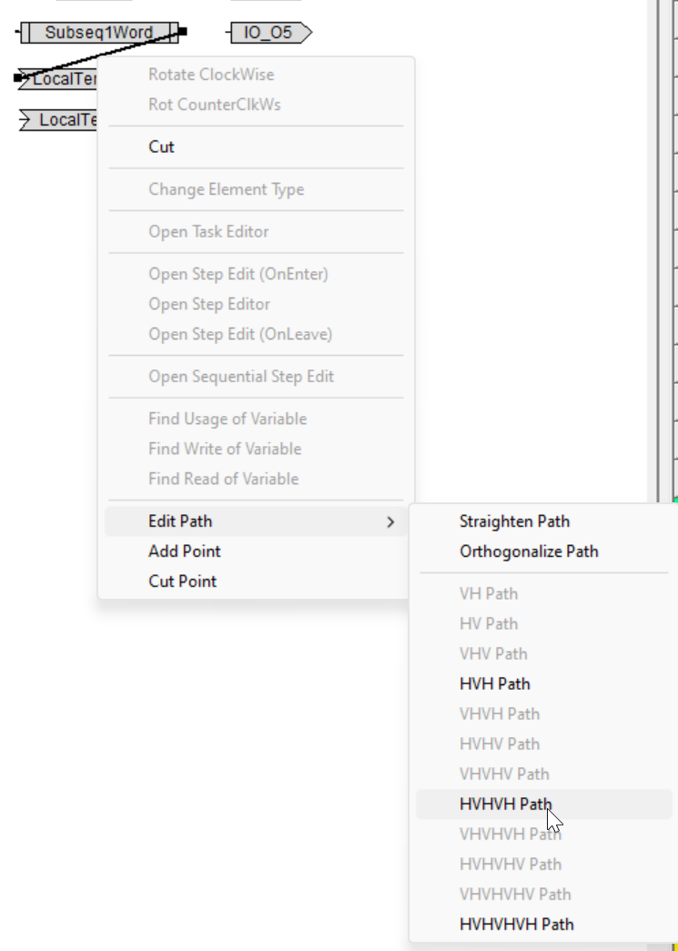
Edit the Path
Right-click on a line>Edit Path>HVHHVH Path to organize the lines connected by parts.
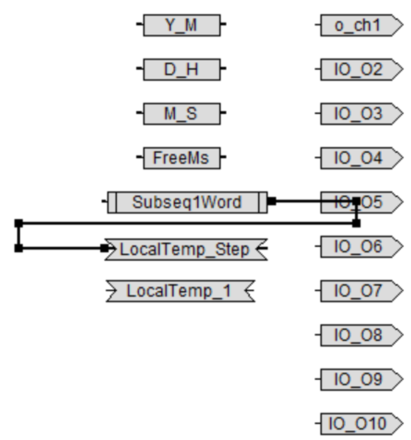
Done!
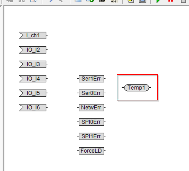
Access the Global Variables
Add the Word Variable Name component. This component is designed to allow variables in the project to be accessed more freely in the Task Model.
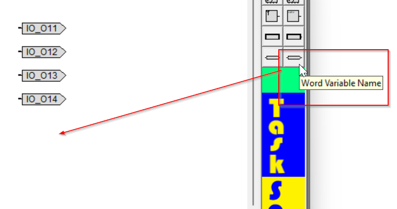
Done!

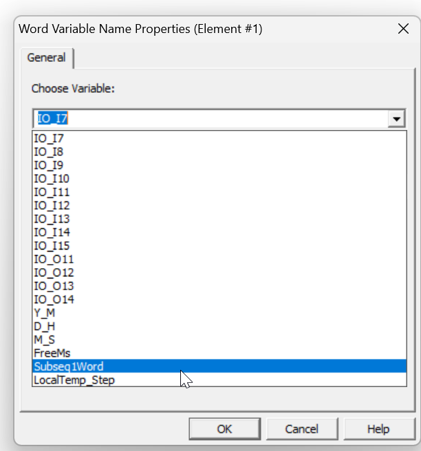
Double-click to edit the part.

Choose Variable
You can set variables to be associated with the relevant Word Variable parts.
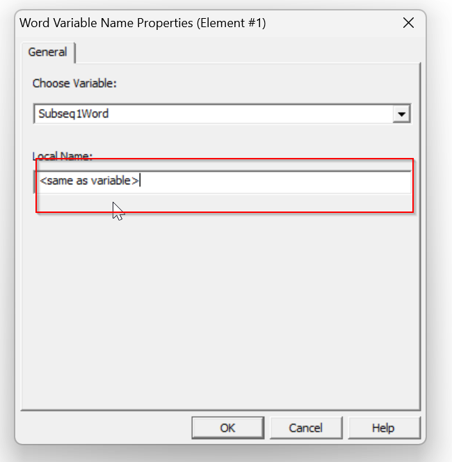
Local Name
This function allows you to set the display name of the variable in the Step.
The default is <Same as variable>, which means that the variable name is the same as the variable to which it is attached, but if the variable name is long, this feature can be used to improve the readability of the project.
In this case, we will use Temp1.
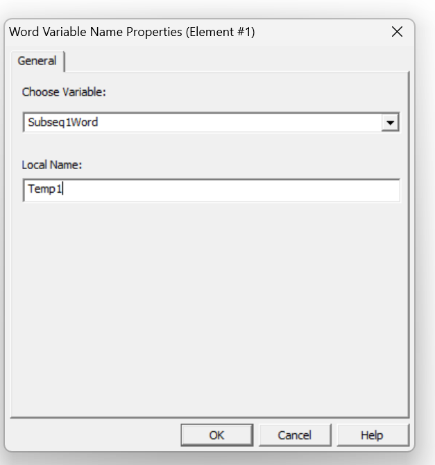
A variable named Done!Temp1 has been added.
Access the Bit inside the Word
Next, add an Extract component to access the Bit of Temp1 by itself.
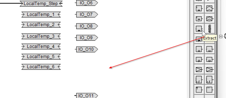
Extract parts have been added.

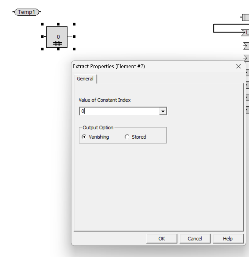
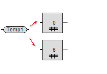
Double-click on the Extract component and you will find a setting called Value of Constant Index.

Value of Constant Index
This is to set how many bits of Word to get True/False.
If it is 0, it will be Bit 0.
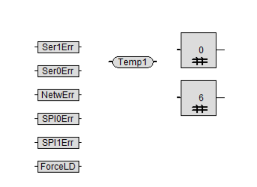
The program is accessing Bit0 and Bit6 now.。
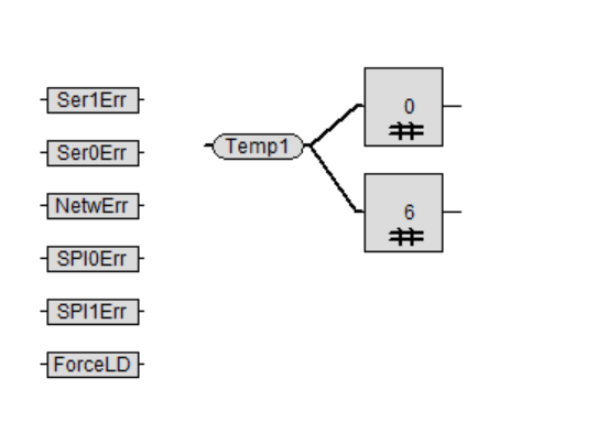
Connect
Connect Temp1 and Extract components.
Done! Now we get Bit0 and Bit6 of Temp1.
Create the OR Logic
Now add the OR Logic component.
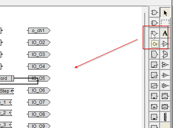
Done!OR Logic components have been added.
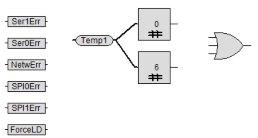
Next, the True/False values of Bit0 and Bit6 taken from Temp1 are connected to the Input of the OR Logic component.
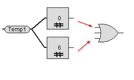
Done!

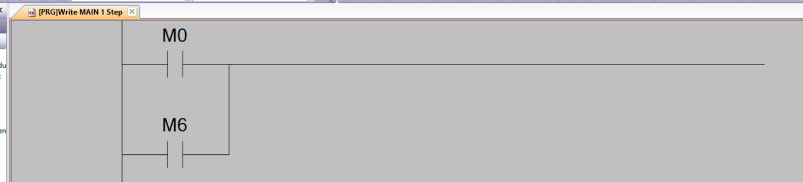
From the ladder diagram, the circuit looks like this
The next step is to connect the OR Logic result to the input of LocalTemp_1.
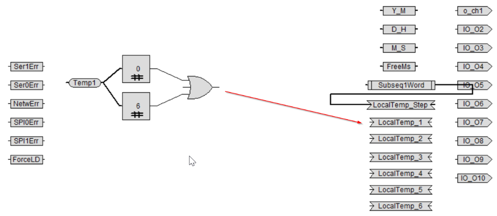
Done!
From the ladder diagram, the circuit looks like this

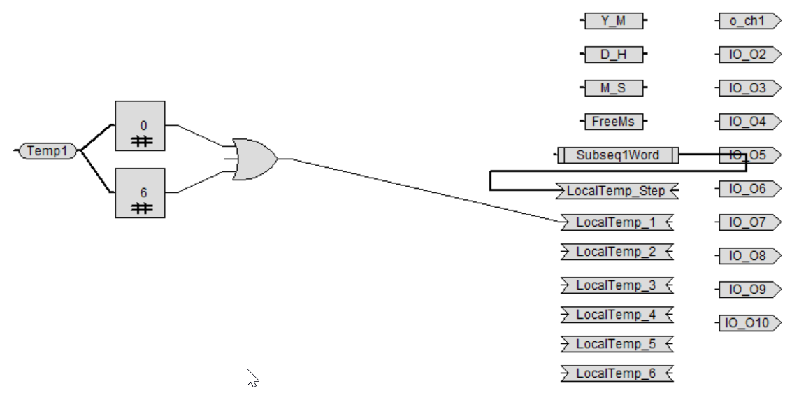
The End Flow
This is the project Flow completed in this article.

IF More than 3 Conditions in One OR Gate…
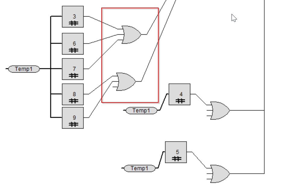
Note that when three or more OR Logic components are to be connected at the same time, they should be separated by two OR Logic components as shown in the figure below.
Call the Model
Finally, to invoke the Task Model, go to Project>Open Context Diagram Editor.

Go to Main>Right click>Open Task Editor.
Let’s add the OutSeq Task Model that we just added.

Result
You can see Flow in action in this video.
Download
You can download this project from the Github Link below.
https://github.com/soup01Threes/Taskscript/blob/main/char04.hgr