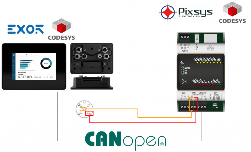
In this Tutorial I will show you how to configure a CANOpen Network with EXOR XA5 panel and Pixsys PLC – Codesys are installed both. EXOR XA5 is the Master side and Pixsys is the slave side.
Let’s start!
Reference Link
http://soup01.com/en/category/exor/
XA5?
The XA5 is an HMI designed for outdoor applications where robust and flexible instrumentation is required. A wide operating temperature range of -30°C to + 70°C is possible for reliable outdoor operation under the harshest environmental conditions.
https://www.exorint.com/en/product/rugged-hmi-xa5
Advanced power management and software optimization enable fast startup and user-configurable control of standby/wakeup states. Low power consumption in standby mode is an important feature for battery-powered applications.
- Programmable with JMobile software
- Optional CODESYS PLC
- Optional Corvina Platform connectivity
- CAN FD ports x2
- Ethernet Interface x 2
- RS-485, isolated x 1
- Weight 0.6 Kg
- IEEE 802.11a/b/g WI-FI

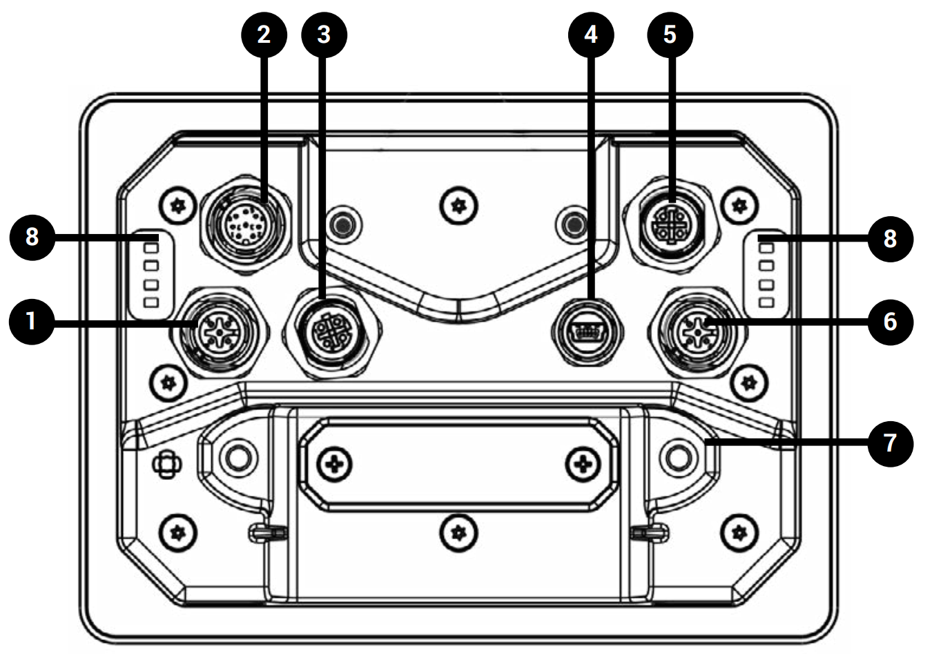
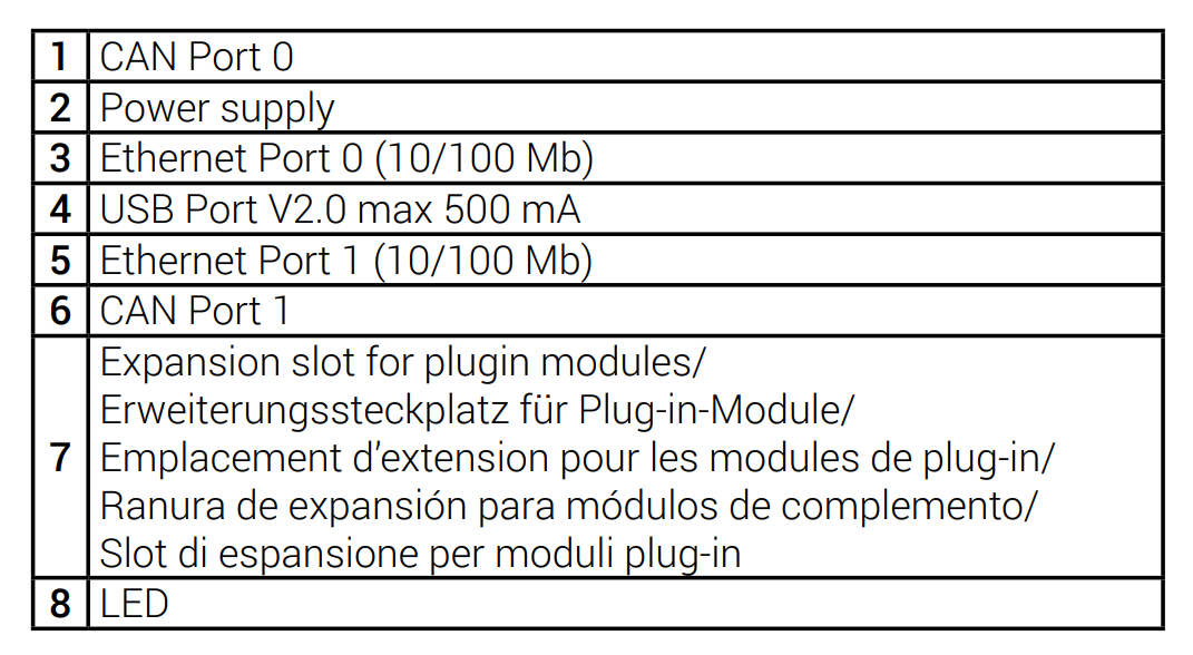
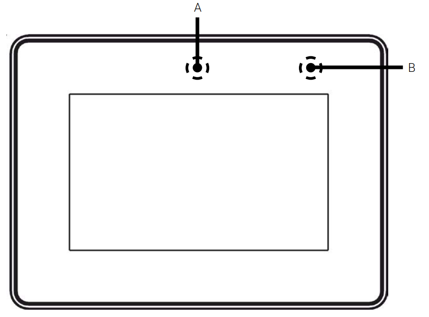
Layout
This is the Layout of EXOR XA5.
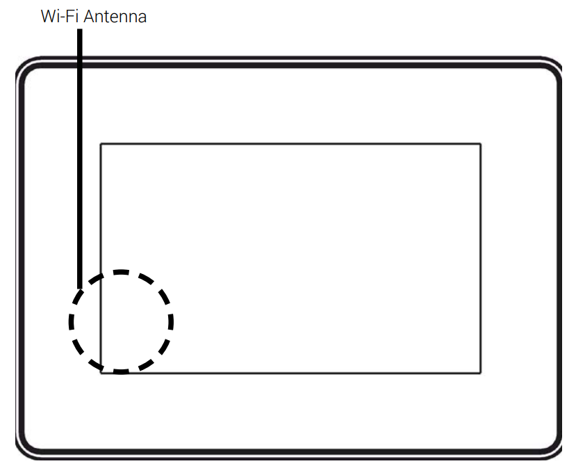
Antenna
This is the location of the WI-FI antenna.
Light Sensor/Configurable LED
A=Light Sersnor place where B=for configurable LED place.
LED
This is the meaning of each LED on the back side of XA5.

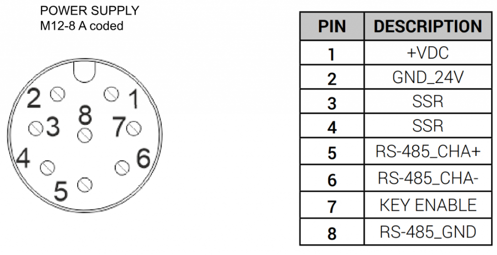
Power Supply
This is the wiring for the power Supply. Note that the KEY ENABLE PIN must also be powered with 24v.

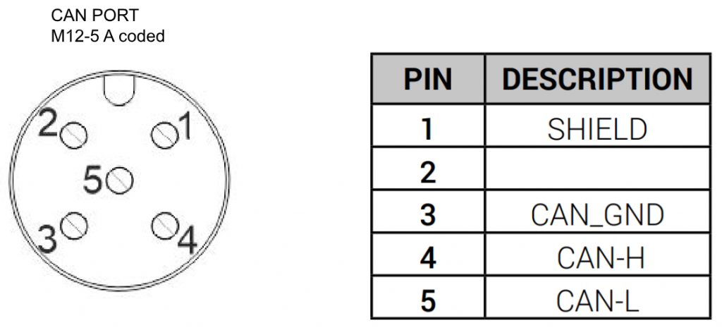
Port
CAN
Power Supply
Implementation
Wiring
This is a wiring diagram.
PlxSys Side
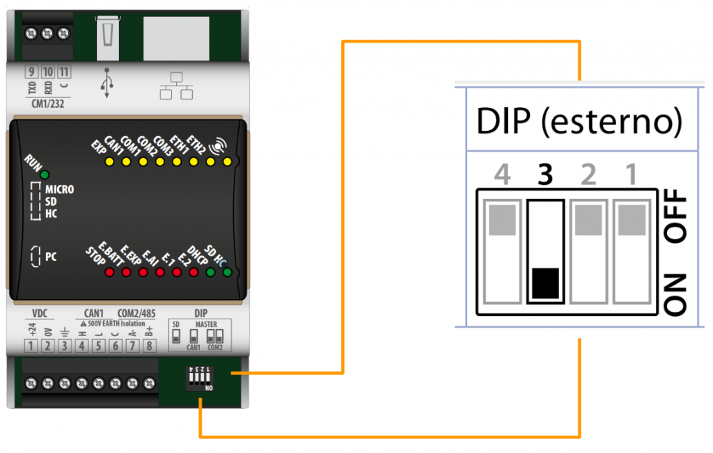
DIP Switch
To use the CAN network, first set DIP switch No. 3 to On.
Add CAN Bus
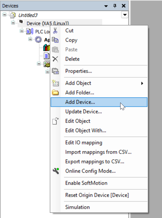
Build a CANOpen Local Slave by clicking the Device>Right click>Add Device.
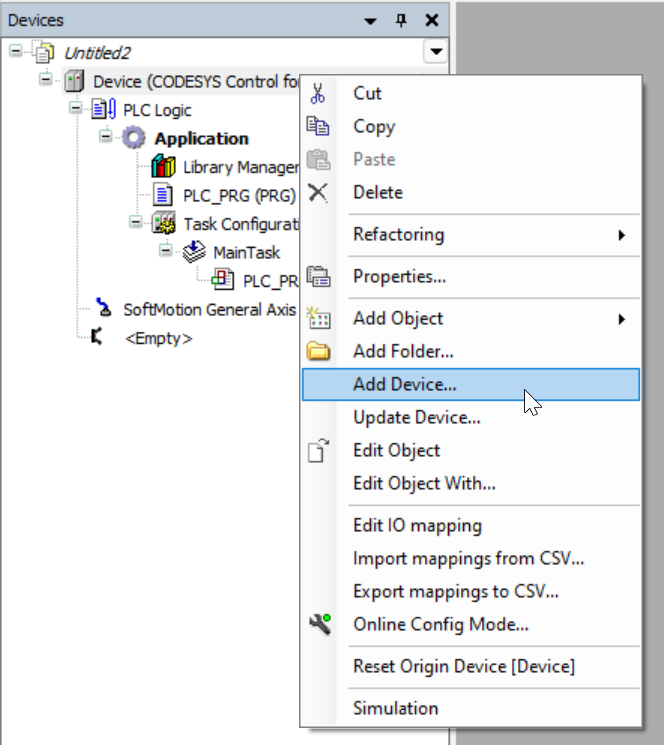
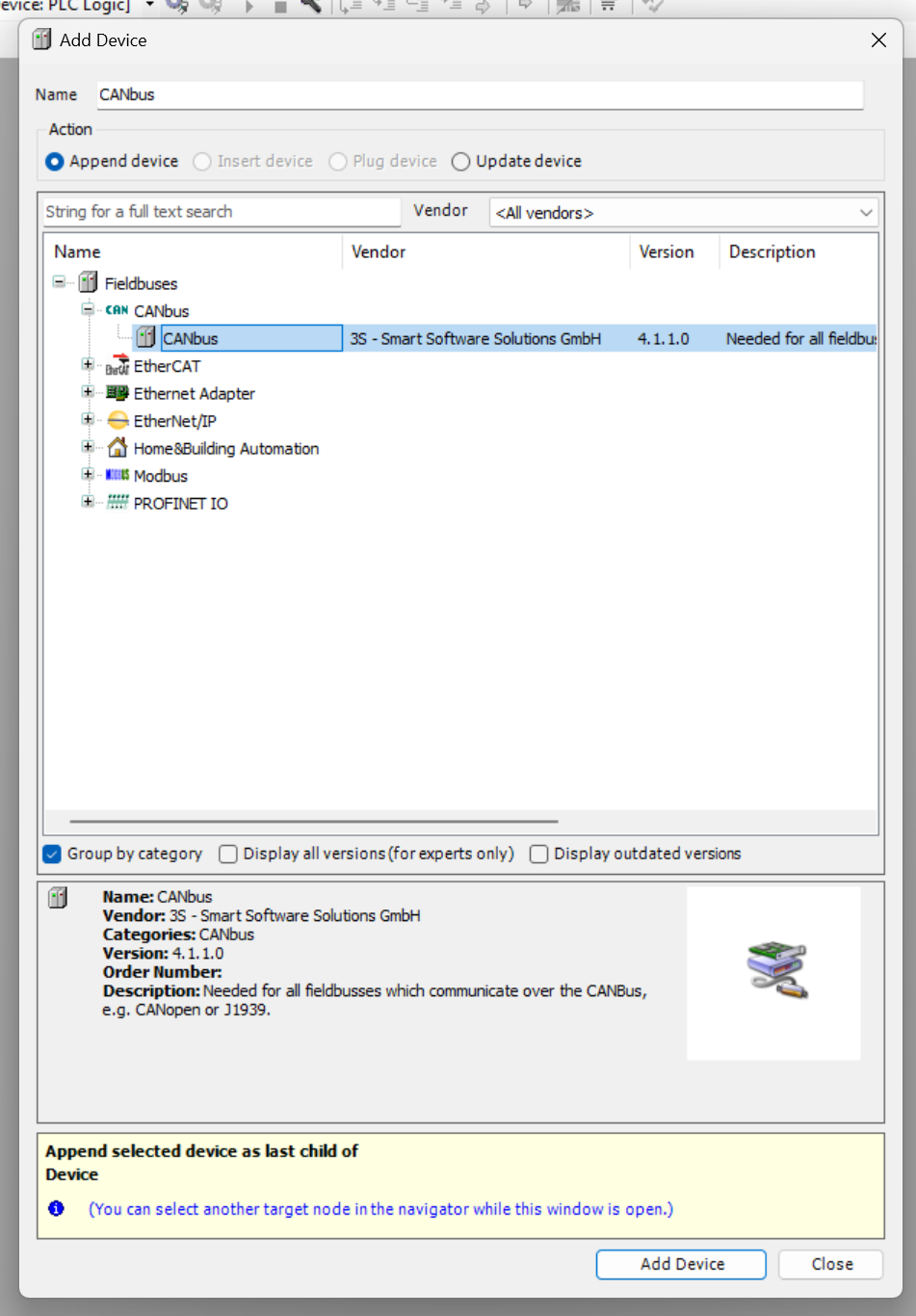
Choose Fieldbus>CANbus>CANbus and Add Device.

Done!CANbus Driver is inserted in your project now.

Add Can Bus Local Devices
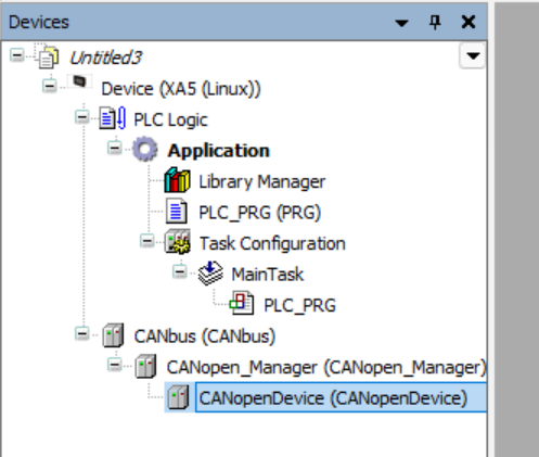
Then we can Add the local CANbus device with right Click>Local Device>CANOpen Device and Add Device.

Done!CANOpen Slave is inserted in your project now.

IF missing Library
Missing Library errors may occur each time a new device is added.

Go to Library Manger>Download Missing Libraries and download the missing libraries.

Parameters
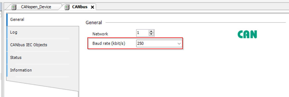
Now we can configure the CANbus parameters.
Canbus(CANbus)
Double click the Canbus(CANbus) and General Tab is displayed.

Network
Please configure the Network to 1(0=Pixsys CPU Local CANBus,1=the CANBus terminal interface of 4 and 5)

Baud rate
Configure the Baud rates to match your applications.
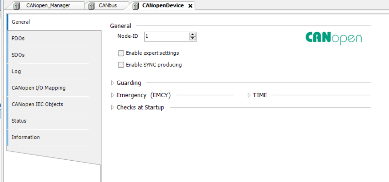
CANopen Device
Then we can configure our CANOpen Device settings.
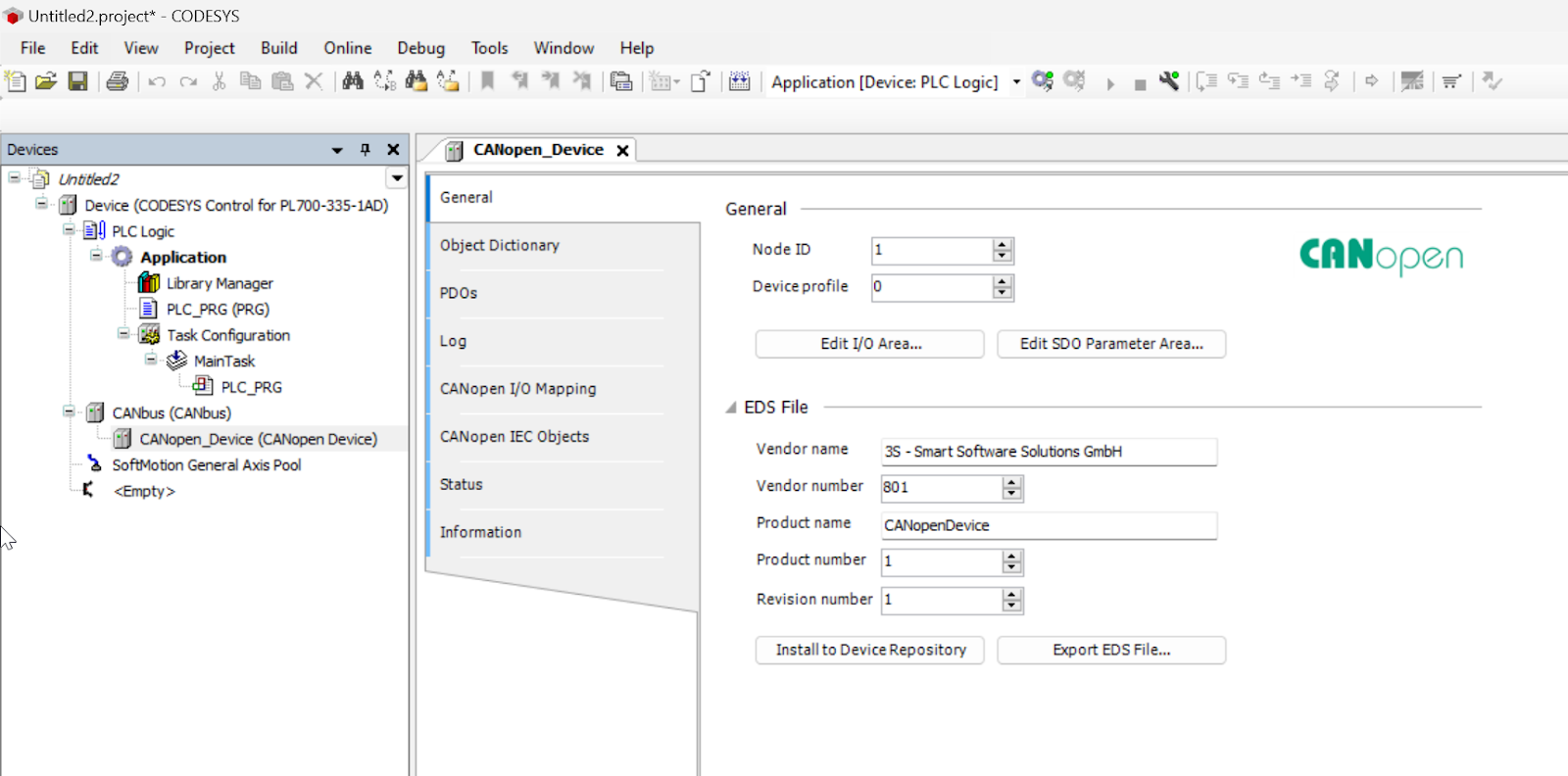
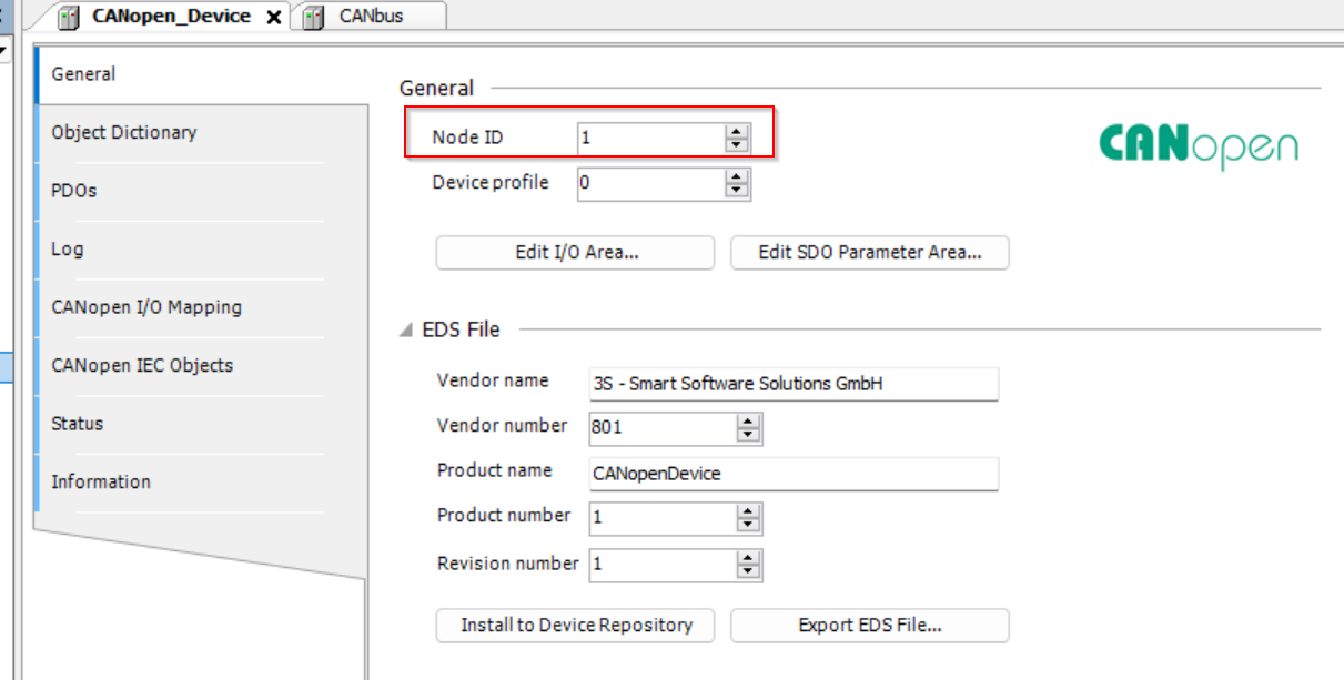
Node ID
You can configure the NodeID that depends on your application.(Default=1)
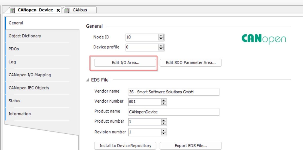
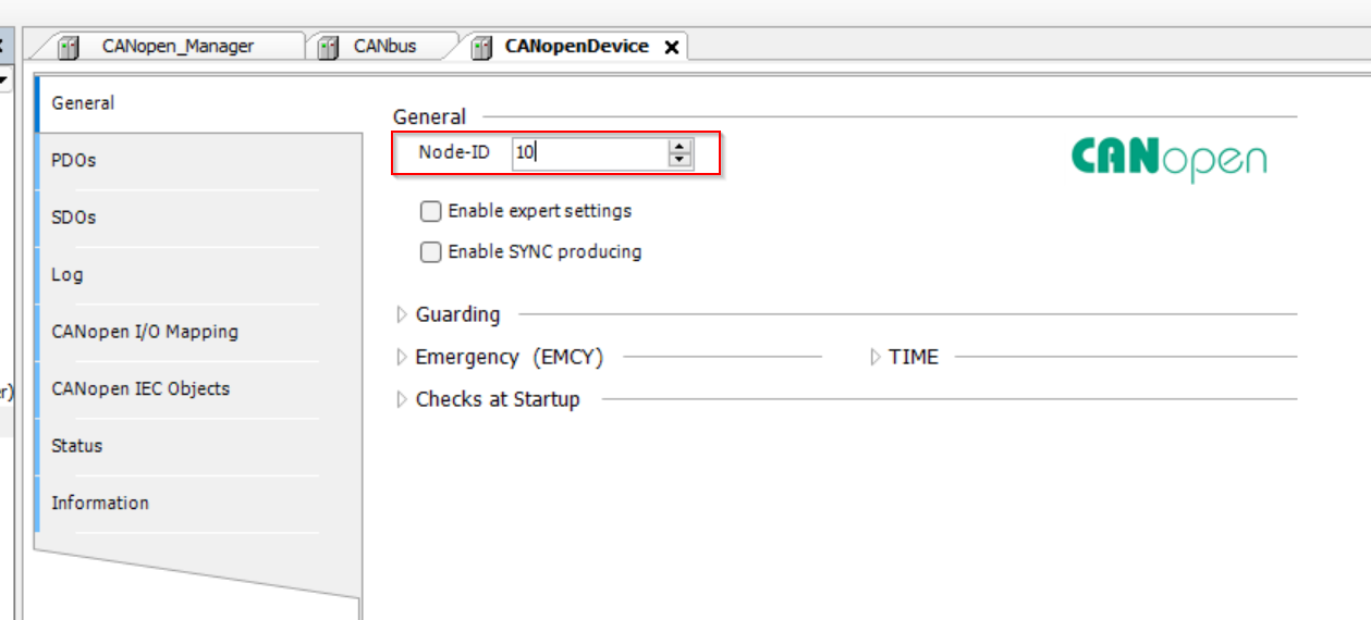
Let’s change the NodeID to 10 and you need to match the NodeID settings in the CANOpen Master Side.

Edit I/O Area
Next, we need to set the data size, direction that would be exchanged with the Master.
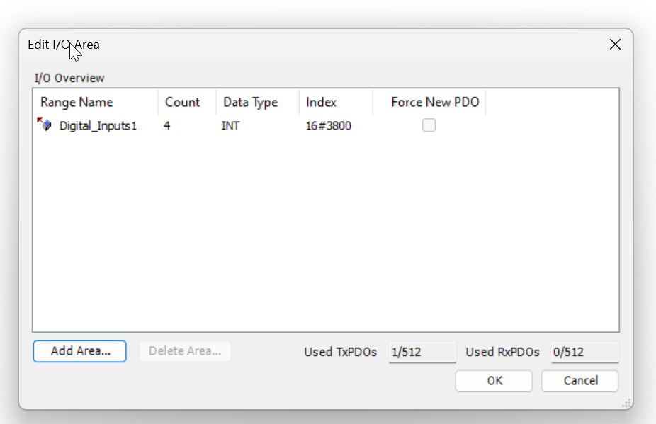
The Edit I/O Area screen appears.
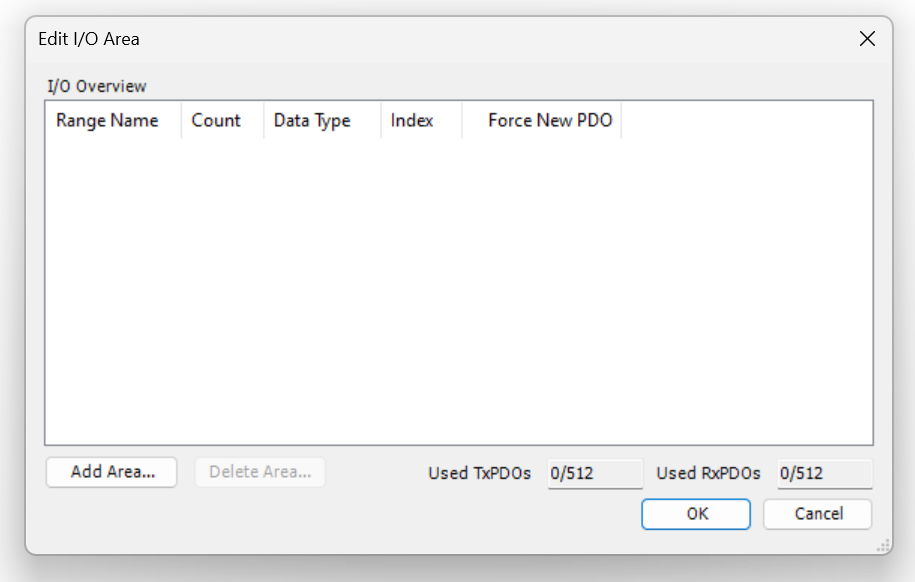
Add Transmit
Declare a new data exchange area with Clicking the Add Area button.

Set I/O direction to Transmit. In other words, this is the Q data output from Pixsys to XA5.

Data Type allows you to set the data type to be exchanged. In this case, let’s use INT (16 Bit integer) from Drop-List.
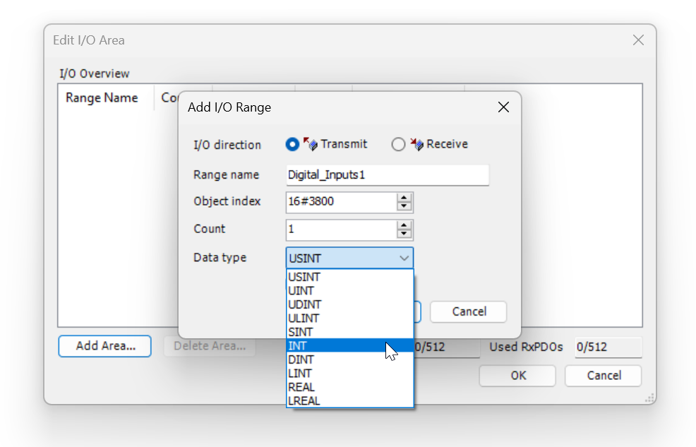
Count is the field that allows you to set the number of identical data in a sequence; Count=4 means four 16-bit integers.

Done!Transmit direction (output) data has been defined.
Add Receive
Next, click Add Area one more time and set the I/O direction to Receive; for Pixsys, this data will be input (I). Same as before, let’s define it as four 16-bit integers.
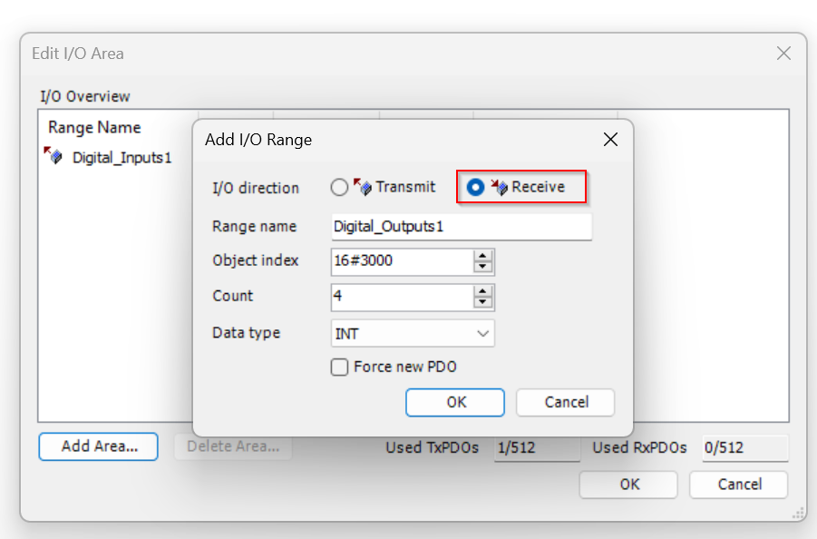
Done!
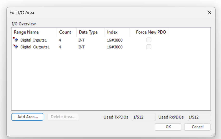
Finally, press the Ok button to save the settings.

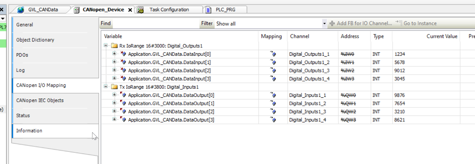
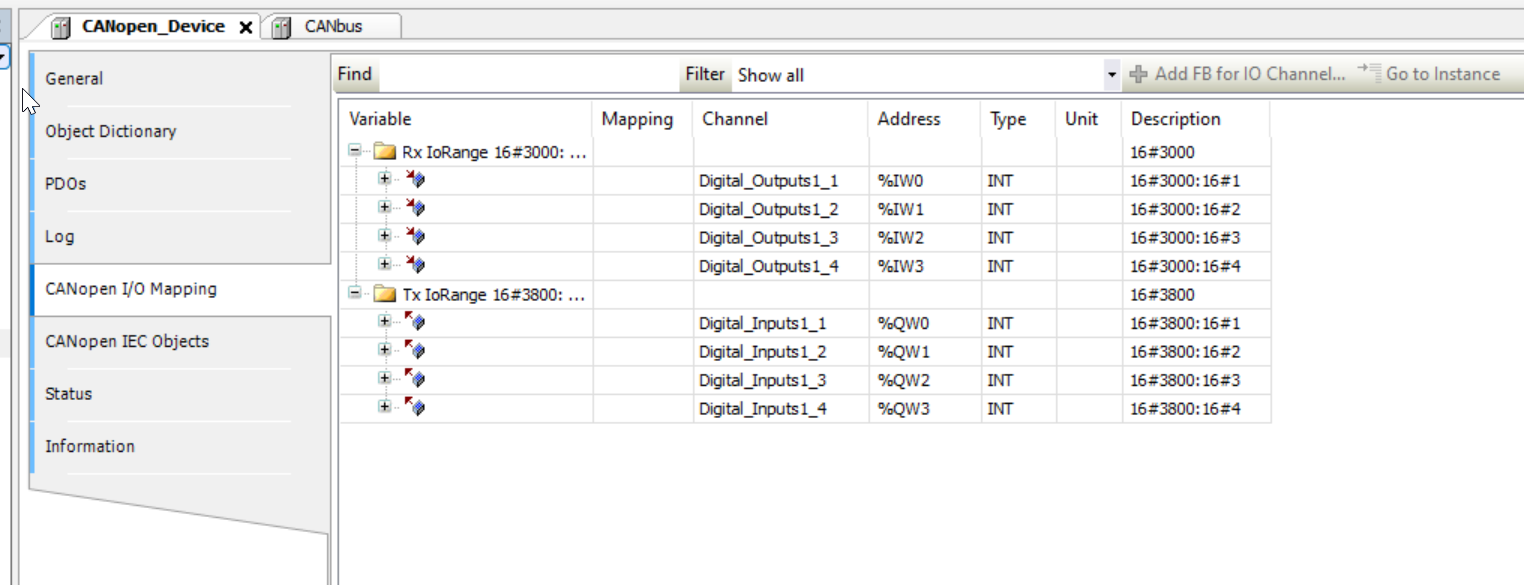
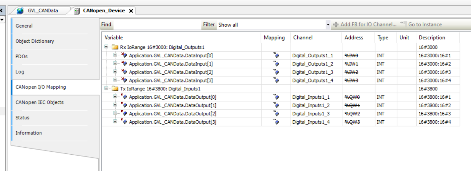
CANopen I/O Mapping
When the CANopen I/O Mapping Tab is opened, the Transmit and Receive data defined earlier are also added and can now be mapped.
Object Dictionary
Next, open the Object Dictionary Tab.
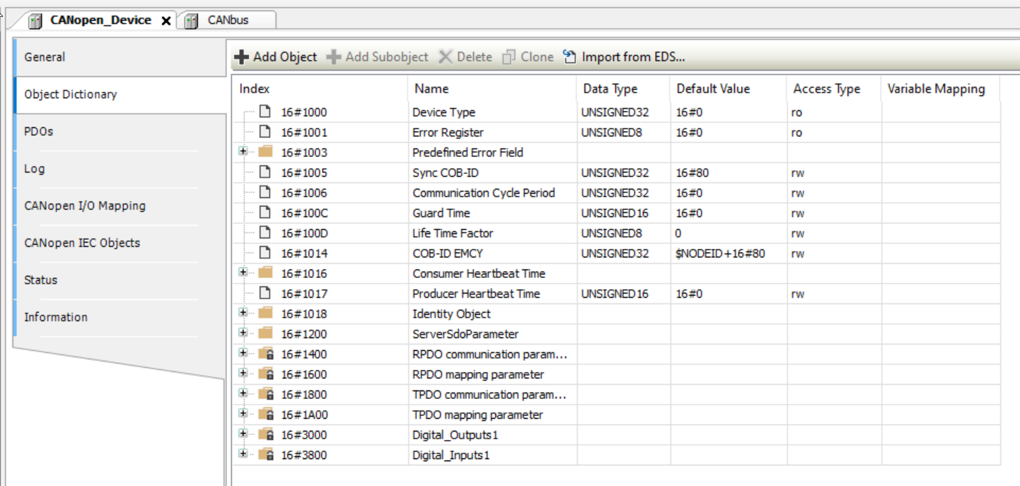
Transmit and Receive data for 16#3000 and 16#3800 were also available.
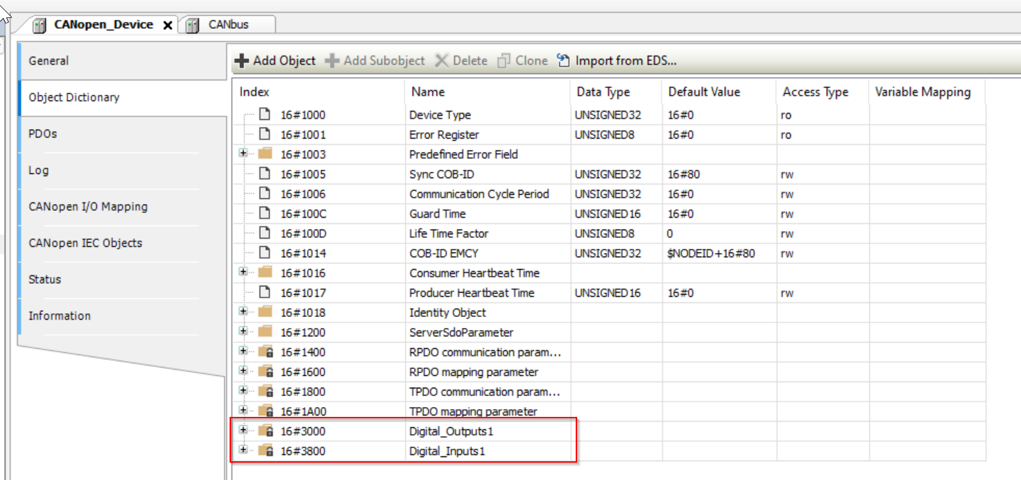

Each Object also has 4 data.

Export EDS File
Next, let’s Export the EDS File.

Set the Export destination.

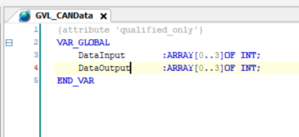
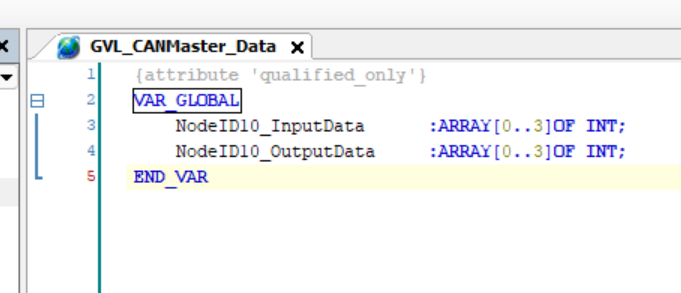
Add GVL
Add GVL for Mapping by click Application>Right click>Add Object>Global Variable List.

Enter the GVL name.

Define an INT array for Mapping.
Mapping
The last step is Mapping GVL variables and CANopen I/O.

Let’s link the I/O to the variables defined in GVL earlier.
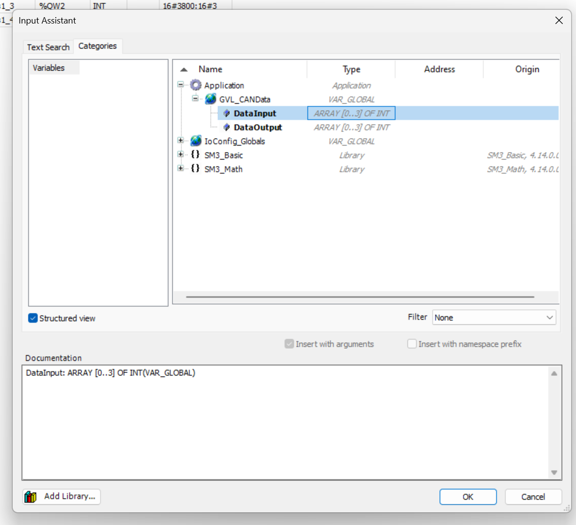
Done!
Program
To check, the program can be checked by putting the appropriate value in each variable.

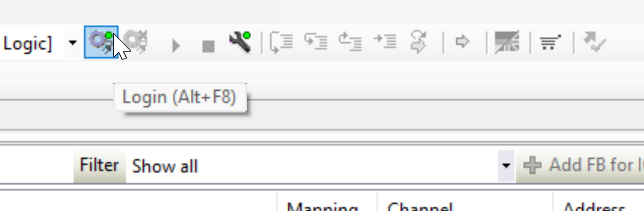
Login
Login to Download the project.
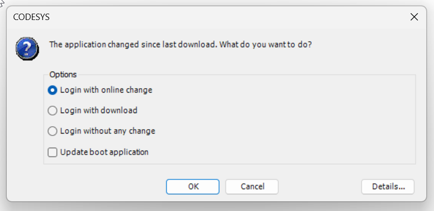
Select Login with online change>Ok.
Then the Codesys CANOpen Slave side of Pixsys is ready.
XA5 Side
Next, we will do the XA5 side: please choose XA5.when you create a new project in Codesys.

Install EDS File
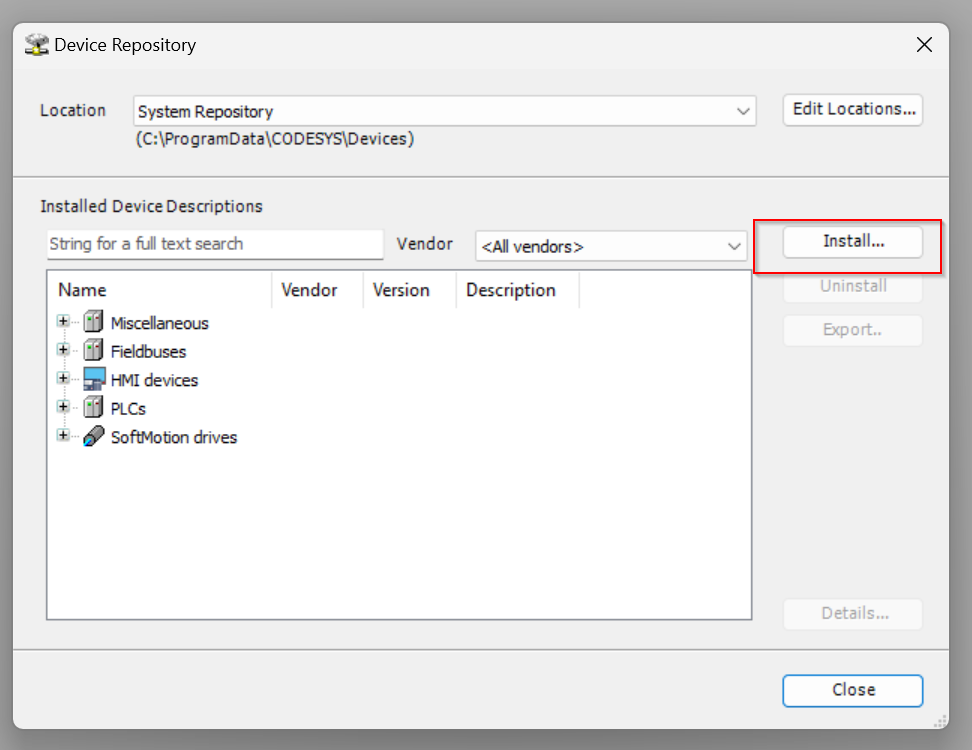
Install the Exported EDS File from the Pixsys project, open Tools>Device Repository.
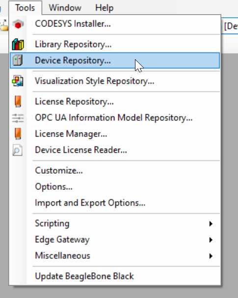
The Device Repository screen appears.

Click the Install button to import the EDS File.
Open the EDS File you just exported.

Add CANbus
To add a CANBus Driver, go to Device>Add Device.
Select Fieldbus>CANbus>CANbus and add CANbus Driver in Add Device.
CANbus Driver has been added.

Add CANopen Manager
Next, add CANopen Master to XA5 Driver by CANopen>CANopenManager>CANopen_Manager.

Done!CANopen Master has been added.

Add CANopen Slave
Now insert the Pixsys CANopen Slave into the CANopen network: Go to Fieldbus>CANopen>Remote Device>CANopenDevice is the EDS file you just imported.

Done!Pixsys CANopen Slave has been added.
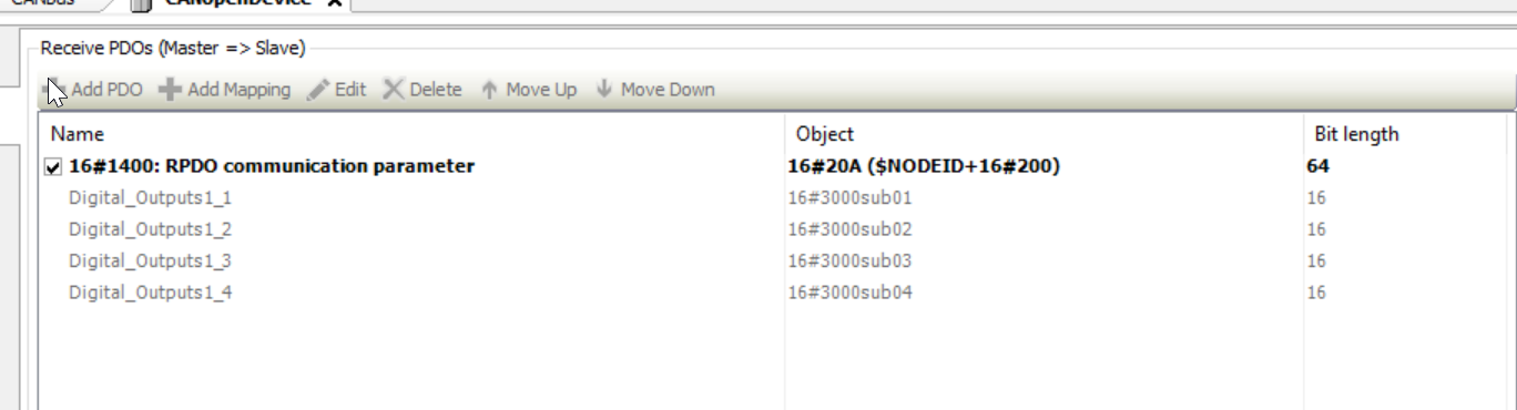
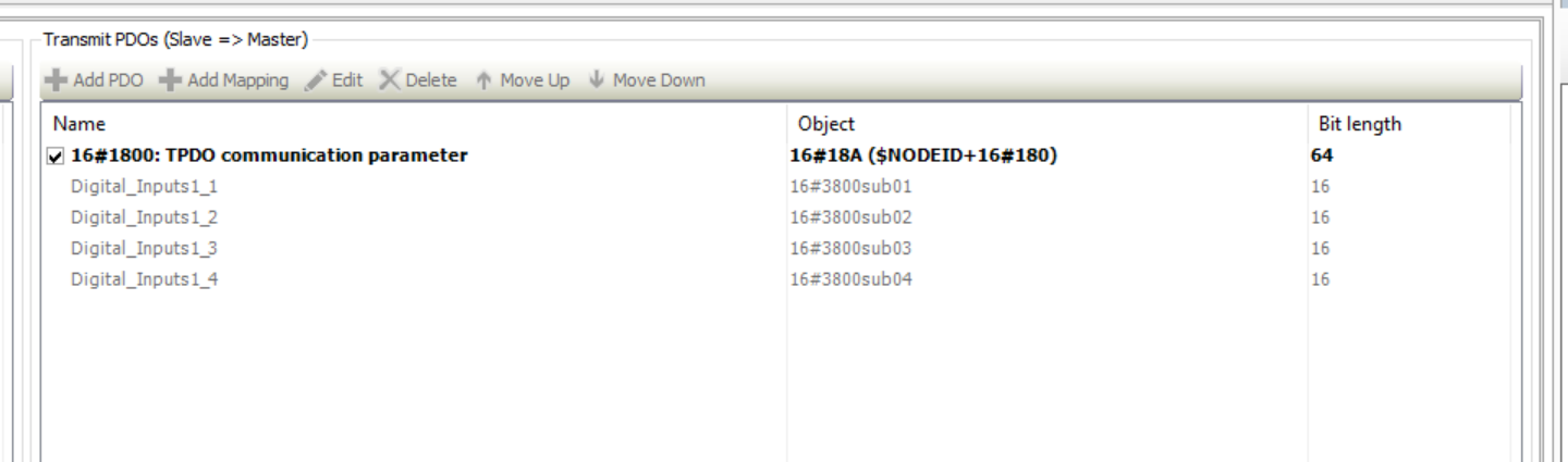
PDOs
Open the Tab in PDOs to see the Process Data Object.

Both Transmit and Receive PDOs were Imported!
Parameters
The next step is to set CANOpen’s network parameters.
CANbus
Network
Set Network=1.

CANopen Device
The next step is to set the communication parameters for Pixsys’ CANopen Slave.

The General Tab appears.
Node-ID
Node-ID=10,which is the corresponding Codesys project in Pixsys.
Add GVL
Define GVL for I/O Mapping: add Application>Add object>Global Variable List.

Let’s define two INT arrays.
CANopen I/O Mapping
The next step is Mapping the variables and IOs defined in GVL.
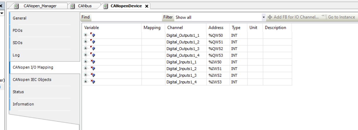
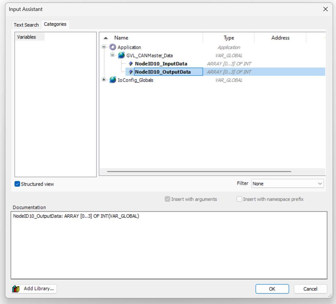
Click the … button.

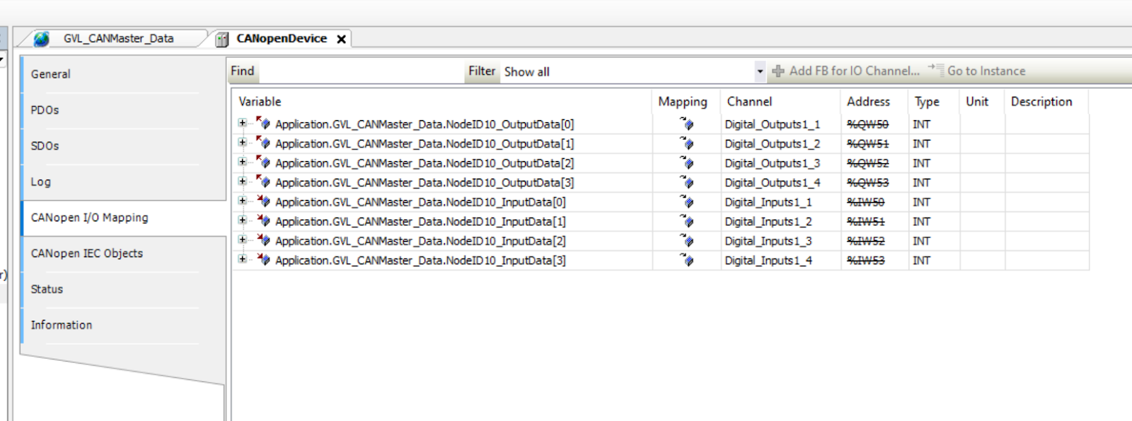
Connect them to the appropriate variables.
Done!

Mapping other I/Os in the same way.
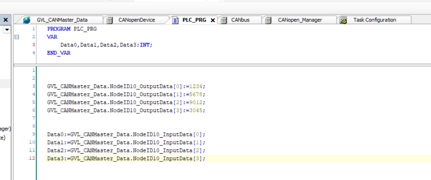
Program
Finally, write appropriate values to the output for verification.
Login
Download the program to Codesys Runtime with Login.
Result
EXOR Side
It has a green ICON next to CANbus, which means it is working properly now.

You can check the current CANbus status from Status.

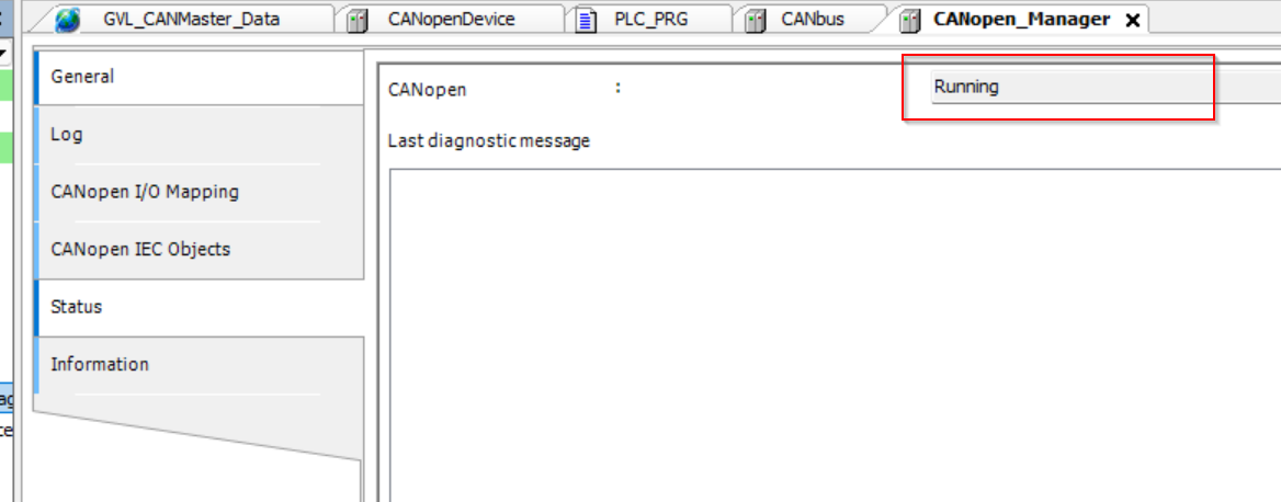
From CANopen Mangaer’s Status, we can see that CANOpen Master is now Running.
You can check the detailed operation history in the Log.

Output data from Pixsys was also received.
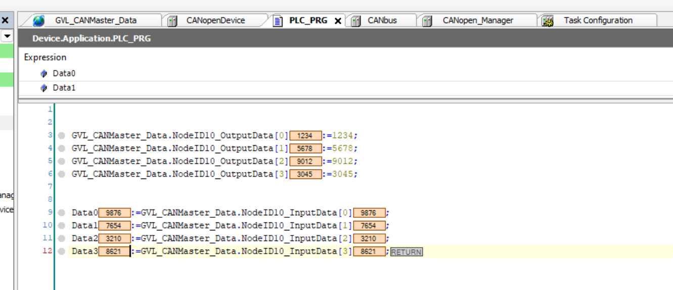

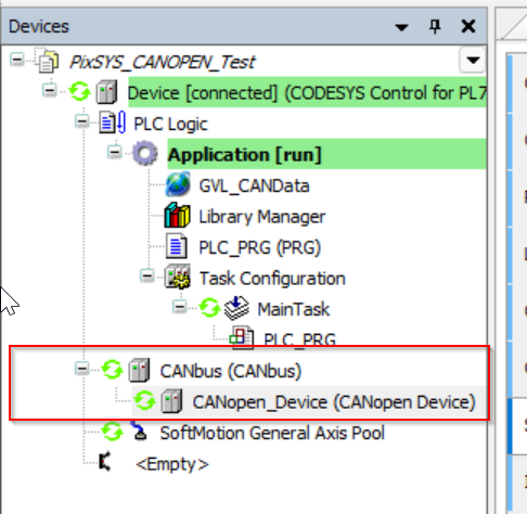
PixSys Side
The PixSys side also has a green ICON on the CanBus, indicating that the CanBus is working properly.
Data from EXOR XA5 was also received.