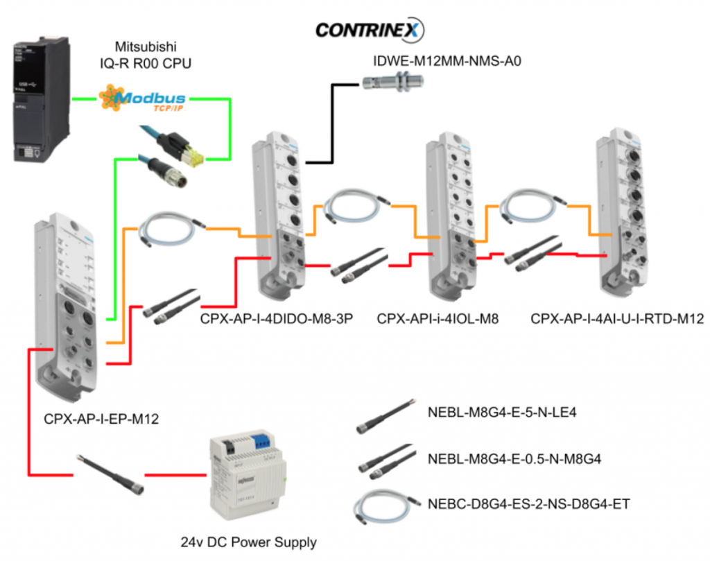
In the previous article, I showed how to build the Ethernet/IP Network from FESTO’s CPX-AP-I-EP module, but this time we use Modbus TCP Mode , Mitsubishi’s IQ-R CPU and its built-in Ethernet Port / Predefined Protocol function to build the network.
In addition, we will also introduce the diagnostic functions of FESTO’s CPX-AP-I-EP module.
Let’s start!
Reference Link
Festo Side
First, I will introduce the Modbus TCP Mode of the Festo module.
Rotary Switch
Since Modbus TCP Mode is used this time, please set the Rotary switch to 745.
The IP address is 192.168.1.145 and uses the built in Modbus TCP Function.

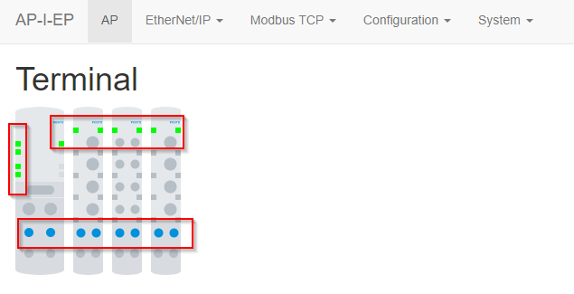
Status
You can check the communication status of the module by accessing the Web Server.
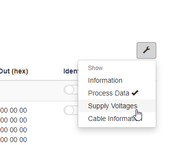
Information
You can check detailed information of each module by clicking the tool ICON.

Process Data
You can check the IO data of each module from the Process Data item.

It is possible to check each module’s raw data.

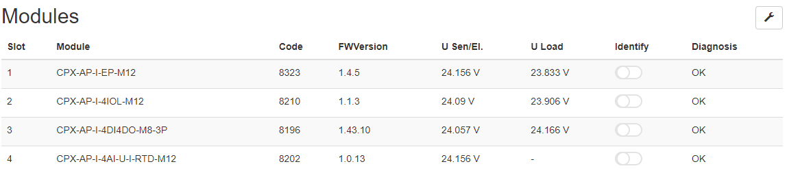
Supply Voltages
Supply Voltages item allows you to check the power supply status of each module.
Cable Information
You can check the length of the cable connected between each module.


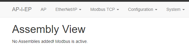
Assembly View
Using Modbus TCP Mode will disable the Ethernet/IP functionality and you will not be able to see anything from the Assembly View.
Modbus TCP Function
Instead of disabling the Assembly View, you can check the Modbus TCP function now.
Support Functions
Modbus TCP>Support Function Codesをクリックします。
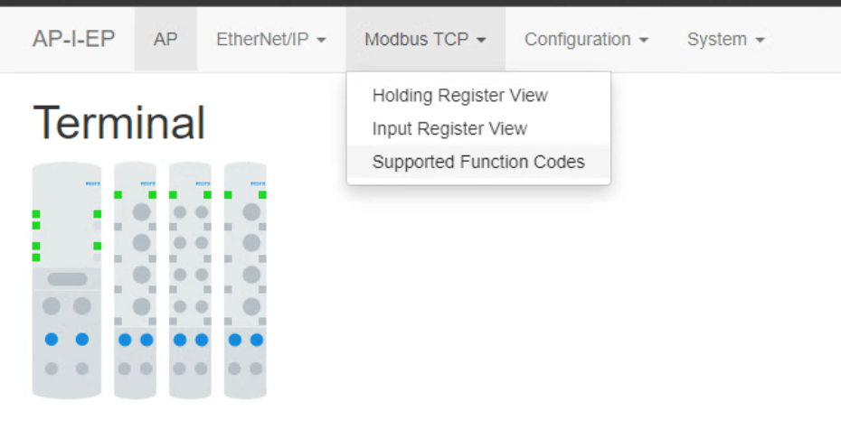
You can also view the list of Function Codes that the module supports.

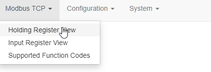
Holding Register
From the Holding Register View, you can check the details of the meaning of each module’s output, register number, etc.

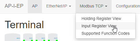
Input Register
From the Input Register View, you can check the details such as the meaning of each module’s input, Register number, etc.

Mitsubishi Side
New Project
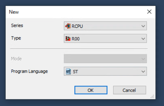
Start GXWORKS3 and create a new project with Project>New.

Select CPU Type etc. and create a project with OK.
Configure IP Address
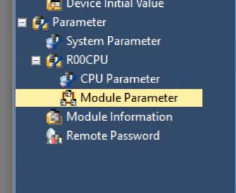
Set the IP address of the CPU by clicking CPU>Module Parameters.
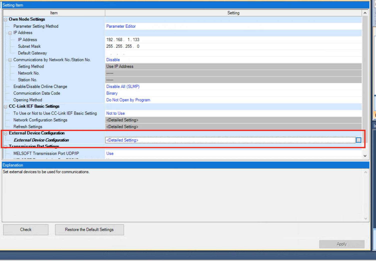
Search IP from Setting Item List.

Set the IP address of the built-in LAN Port and save with Apply.

Setup
We need to configure the Modbus TCP Connections.
Click External Device Configuration>Detailed Settings.
Add Connection
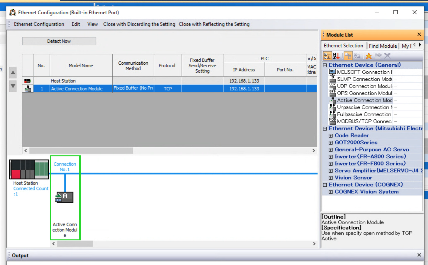
The Ethernet Configuration screen is displayed.

Drop “Active Connection Module” from the Module List on the right.
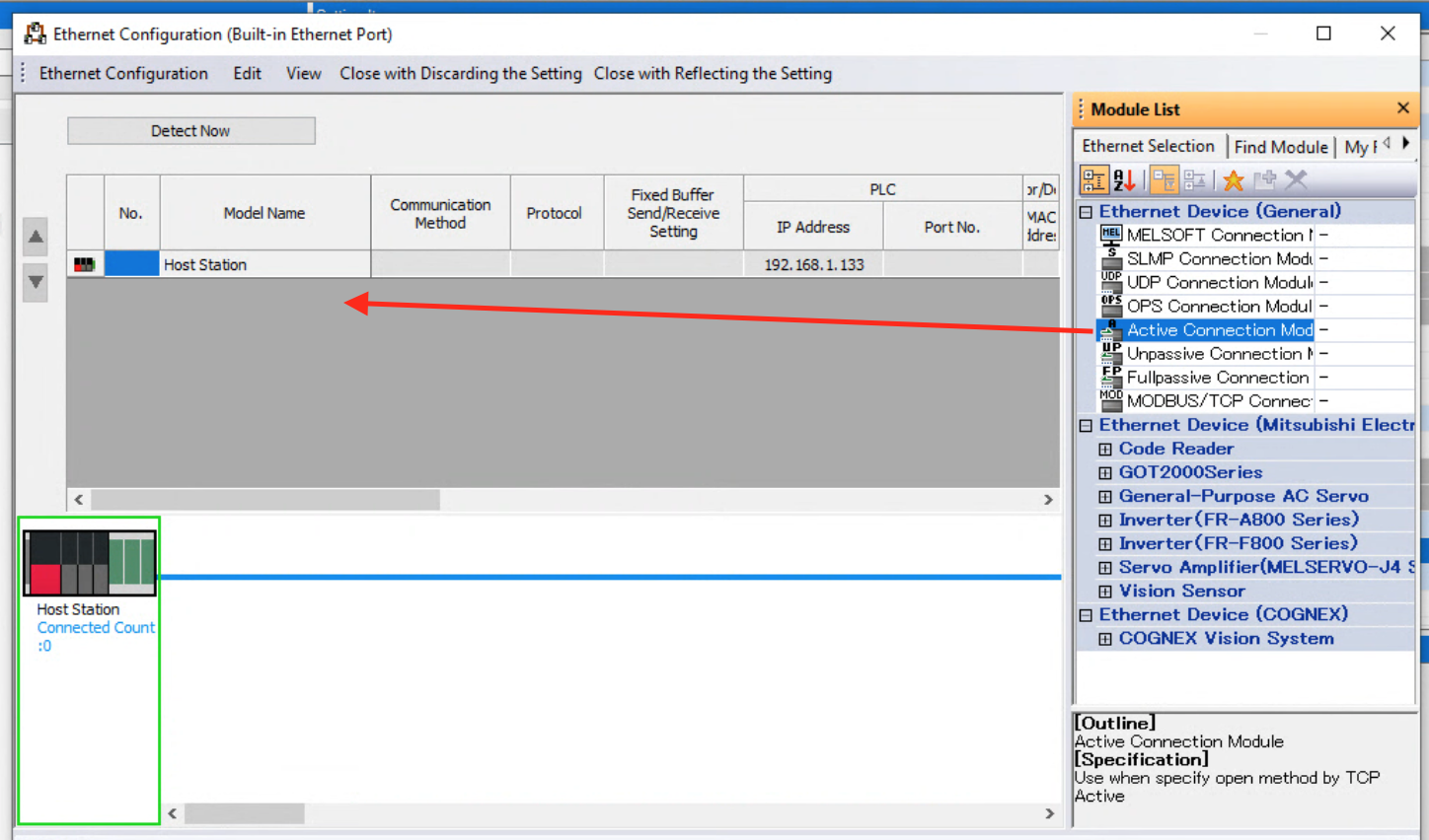
Done! Active Connection Module is added into your configuration.
PLC Side
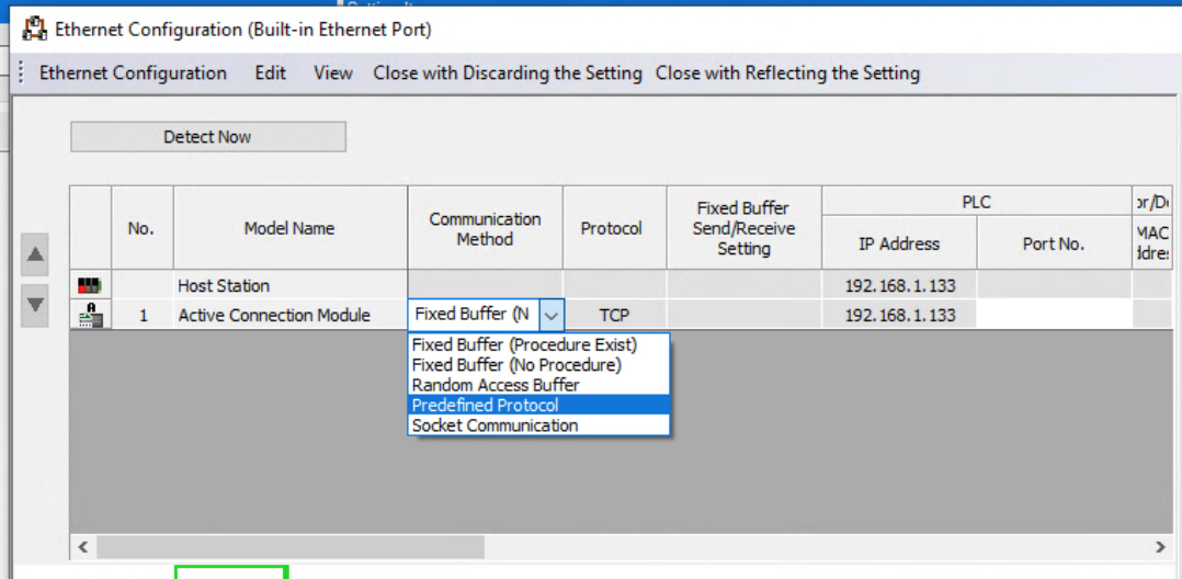
Communication Method
Set Communication Method to “Predefined Protocol”.
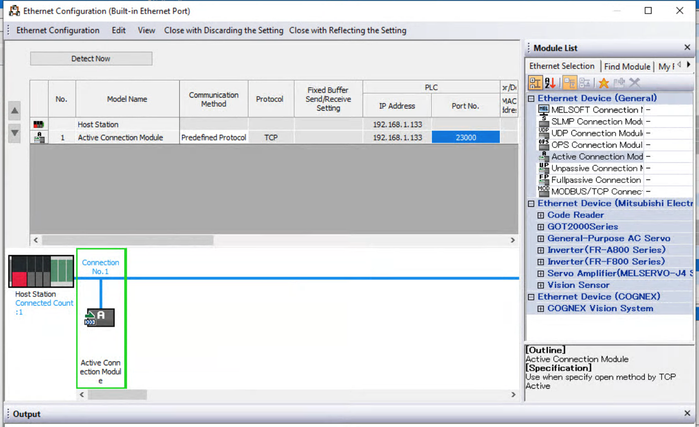
Port
It is OK if you enter a Port number that is not used appropriately inside your Application.
Festo Side
Now we can add the Festo Module. As you see,there is a Sensor/Device item.

Set the IP Address and Port No. In this article, IP=192.168.1.159, Port uses Default 502.

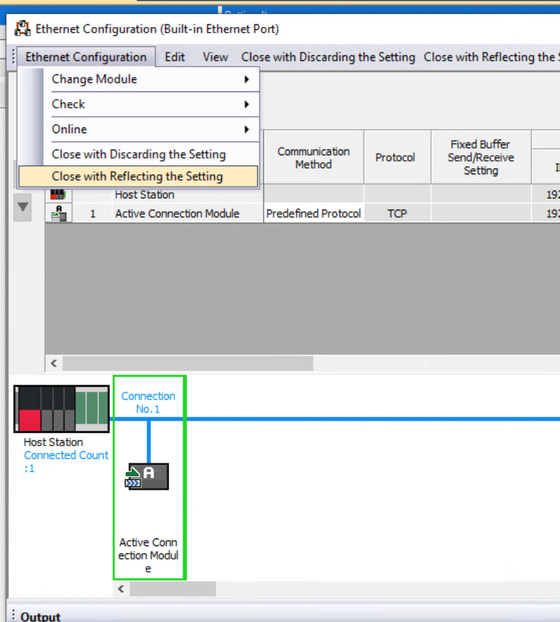
Save it
Save the settings with Ethernet Configuration>Close with Reflecting the Setting.
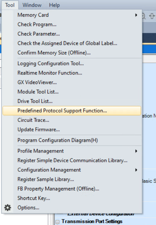
Predefined Protocol Support Function
Open Tools>Predefined protocol support functions.
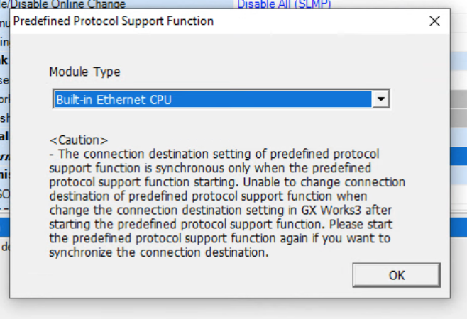
You can select the module type.
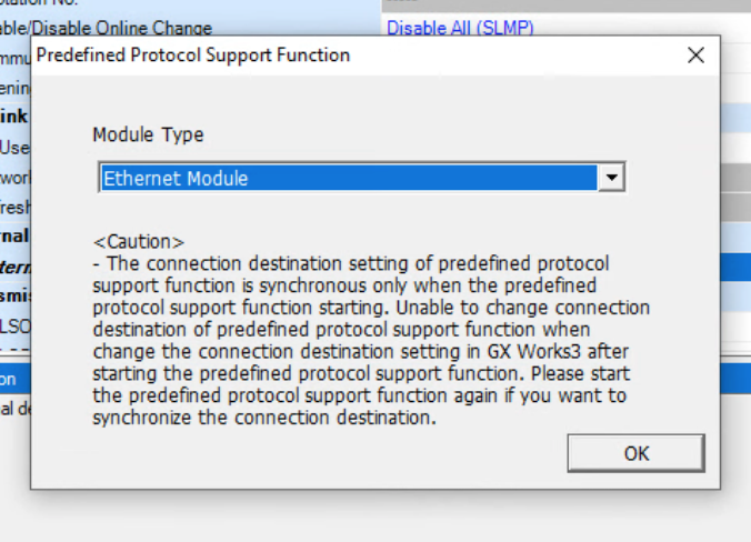
Select the build-in Ethernet CPU from the Drop list.

Confirm with Ok.
The Predefined protocol support function screen is displayed.

New Project
Open a new project with File>New.
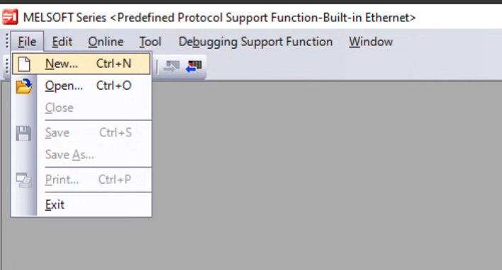
A new predefined protocol support project has been added.
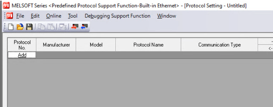
Add Protocol
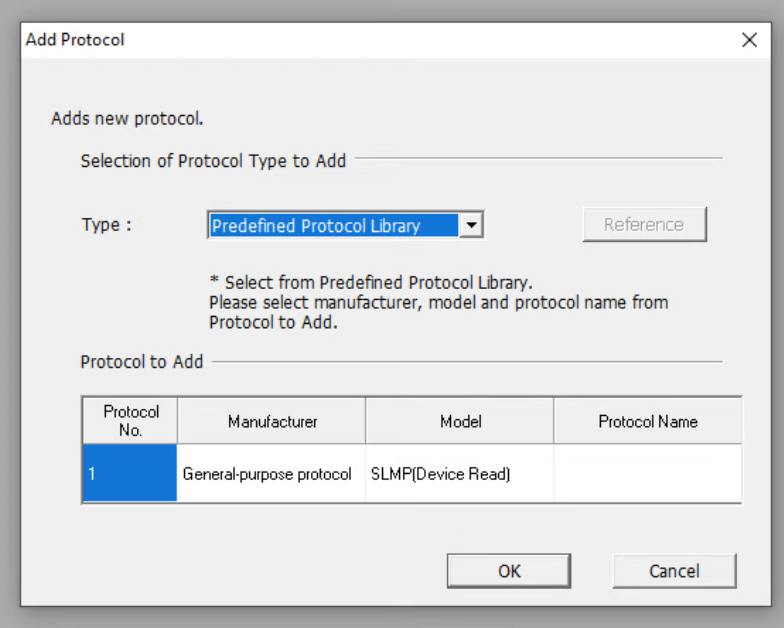
Add a new Predefined Protocol with “Add”.

The Protocol setting screen is displayed.
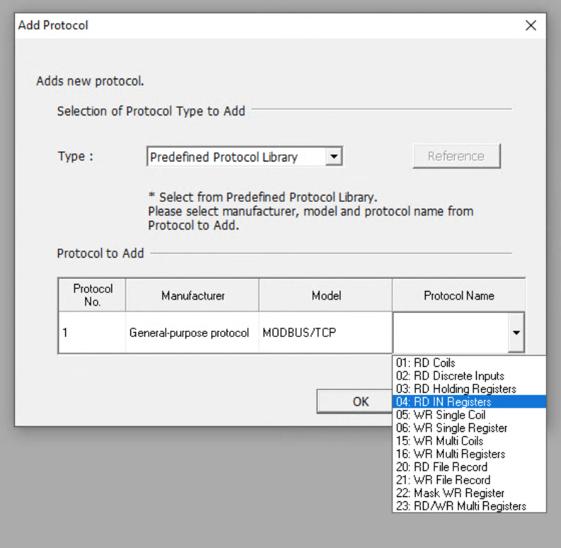
Protocol No.1
Select MODBUS/TCP from the Model item.

Set 04: RD IN Register to Protocol Name, It means Function Code04.
Added Protocol No.1. is added.
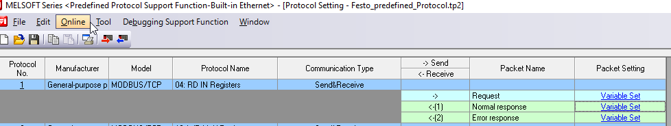
Request
04: Set the absolute address corresponding to each part to the Request of RD IN Register.
- D100: Transaction ID
- D101: Module ID
- D102: Start number of Input Register to read
- D103: Number of Registers to read

Normal Response
Next, set the absolute address corresponding to each part in the normal Response of 04: RD IN Register.
- D110:Transaction ID
- D111: Module ID
- D1000, D1001-D1125: Transfer destination of read data

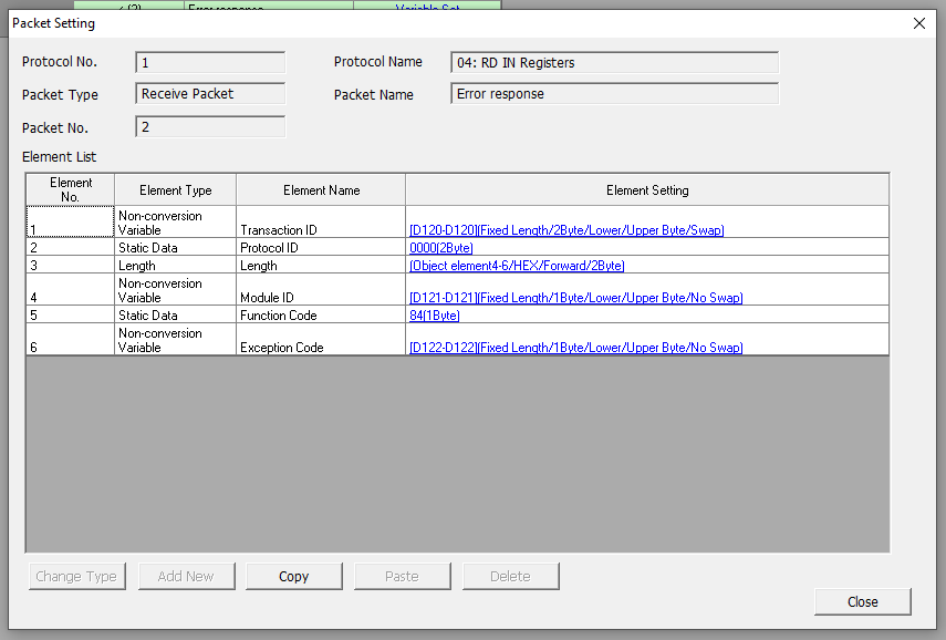
Error Response
Finally, set the absolute address corresponding to the Error response of each part in 04: RD IN Register.
Protocol No2.
Create the second Protocol just like Protocol No1. The Protocol type is 16:WR Multi Register, It means Function Code 16.

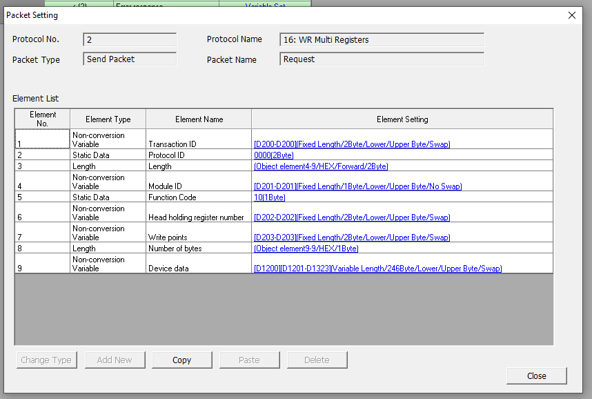
Request
16: Set the absolute address corresponding to each part to the Request of WR Multi Register.
- D200: Transaction ID
- D201: Module ID
- D202: Start number of Holding Register to write
- D203: Number of Holding Registers to write
- D1200: Totol size for writing (in bytes)
- D1201-D1323: data to write
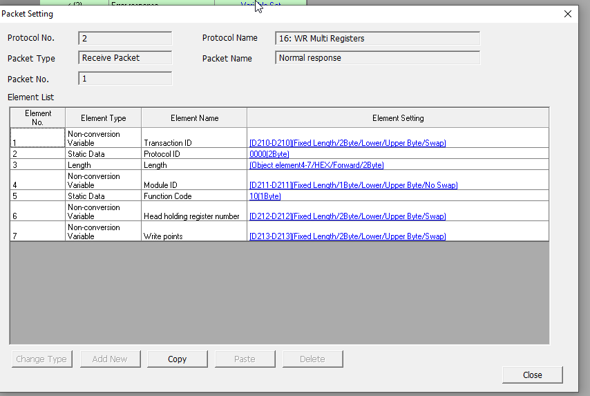
Normal Response
Next, set the absolute address corresponding to each part of Request – 16:WR Multi Register.
- D210:Transaction ID
- D211: Module ID
- D212: Head Holding Register number
- D213: Number of Registers written
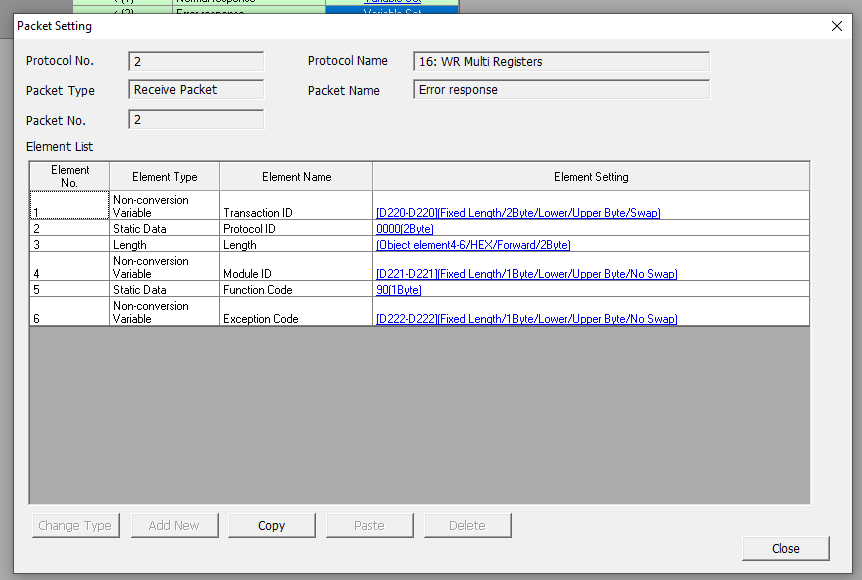
Error Response
Finally, set the absolute address corresponding to the Error response of each part in 16:WR Multi Register.
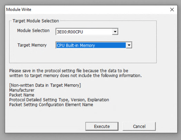
Write to Module
Press Write to Module to download the configuration to CPU.

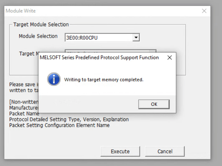
Execute it.
Done!
Program
Function
Before introducing the program, I will first introduce the functions used in this tutorial.
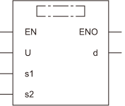
SP_SOCOPEN
This function can open a Connection.
Parameters
| Operand | Descirption |
| U | Dummy |
| s1 | Connection Number |
| s2 | Control Data |
| d | The status of function execution |
s2
| s2+0 | Whether the function uses control data or Open Settings0000H=Open Settings・8000H=Use control data |
| s2+1 | function execution result, 0=success |
| s2+2 | Connections setting |
| s2+3 | Source port number |
| s2+4、s2+5 | IP address |
| s2+6 | Destination port number |
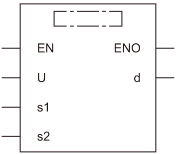
SP_ECPRTCL
This function uses the Pre-definedProtocol to send the request to the destination.

Parameters
| Operand | Descirption |
| U | Dummy |
| s1 | Connection Number |
| s2 | Protocol function to process |
| s3 | Control data |
| d | Function execution state |
s2
| s2+0 | Number of protocols successfully executed |
| s2+1 | function execution result, 0=success |
| s2+2-s2+9 | Protocol number to execute |
| s2+10-s2+17 | 0=Applicable protocol is receive only |
SP_SOCCLOSE
こちらの関数を使用し、Connectionを閉じることができます。
Parameters
| Operand | Descirption |
| U | Dummy |
| s1 | Connection Number |
| s2 | Control data |
| d | Function execution state |
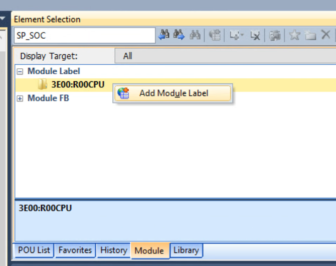
Add Module Label
Right-click Element Selection>Module Label>R00CPU and add a CPU label with>Add Module Label.
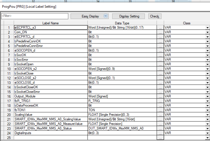
MAIN

Local Label
This is the local label used in this project.
DUT_SMART_IDWx_MxMM_NMS_A0
This is a Contrinex smart sensor state struct.

OB100
This ST is a program that resets all flags in the CPU when the CPU goes from STOP>RUN.

| //Init the Parameters IF RCPU.stSM.bAfter_RUN1_Scan_ON THEN bSocOK:=FALSE; bSocError:=FALSE; bSocketOpen:=FALSE; bPredefineConnError:=FALSE; bPredefineConnOK:=FALSE; bSocketClose:=FALSE; bSocketCloseError:=FALSE; stECPRTCL_s3[2]:=1; //we will only use this control word and change it dynaimiclly stECPRTCL_s3[3]:=0; stECPRTCL_s3[4]:=0; stECPRTCL_s3[5]:=0; //Protocol Number1 D100:=1; //Transaction ID D101:=1; //Slave ID D102:=0; //Starting Register Number D103:=39; //Your Reading Points //Protocol Number2 D200:=2; //TransactionID D201:=1; //Slave ID D202:=0; //Starting Register Number D203:=33; //Write Points D1200:=66; //Totol writing bytes – 33 words END_IF; ; |
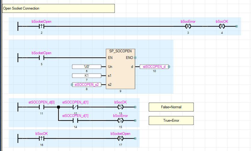
Open Socket Connection
This program opens the Connection1 connection.
bSocOK=Connection successful and bSocError=Connection failed.
Trigger the Pre-definedProtocol
This program sends a Pre-definedProtocol request to the connection destination of Connection1 (Festo module in this article).

s2は常に1を入れていますが、実際はその関数の制御データを変更し異なるPre-definedProtocolをFestoモジュールに送信します。そしてSTB_1にはそのPre-definedProtocolを切り替えと入出力データをEncodeするプログラムが入っています。s2 always puts 1, but actually we change the control data of that function and send a different Pre-definedProtocol to the Festo module,and STB_1 contains a program that switches the Pre-defined Protocol and encodes the input/output data.

STB_1
stECPRTCL_s3[2] is a Register to switch the Pre-definedProtocol number. It then encodes the IOLINK Sensor data into the correct format.
| // fbTON1(IN:= NOT fbTON1.Q ,PT:= T#1s); D1:= stECPRTCL_s3[2]; IF bDataProcessOK THEN CASE D1 OF //Protocol 1 1: D0:=1; stECPRTCL_s3[2]:=2; ScalingValue[0]:= (INT_TO_REAL(D1036)/32000.0)*10.0; ScalingValue[1]:= (INT_TO_REAL(D1037)/32000.0)*10.0; ScalingValue[2]:= (INT_TO_REAL(D1038)/32000.0)*10.0; ScalingValue[3]:= (INT_TO_REAL(D1039)/32000.0)*10.0; // SMART_IDWx_MxxMM_NMS_A0_ScalingValue:=D1002 & 16#00FF; //SMART_IDWx_MxxMM_NMS_A0_MeasureValue:= //(INT_TO_REAL(SWAP(EN:=TRUE ,d=>D1001 ))/16383.0)*110.0; M0:=SWAP(EN:=TRUE ,d=>D1001 ); SMART_IDWx_MxxMM_NMS_A0_MeasureValue:= (INT_TO_REAL(D1001 )/16383.0)*110.0; SMART_IDWx_MxxMM_NMS_A0_Status.OSS1:=D1002.8; SMART_IDWx_MxxMM_NMS_A0_Status.OSS2:=D1002.9; SMART_IDWx_MxxMM_NMS_A0_Status.TSS:=D1002.A; SMART_IDWx_MxxMM_NMS_A0_Status.SSC1:=D1002.B; SMART_IDWx_MxxMM_NMS_A0_Status.SSC2:=D1002.C; SMART_IDWx_MxxMM_NMS_A0_Status.ALR1:=D1002.D; SMART_IDWx_MxxMM_NMS_A0_Status.ALR2:=D1002.E; SMART_IDWx_MxxMM_NMS_A0_Status.ALR3:=D1002.F; DigtialInputs[0]:=D1035.0; DigtialInputs[1]:=D1035.1; DigtialInputs[2]:=D1035.2; DigtialInputs[3]:=D1035.3; //Protocol 2 //Holding Register 2: D0:=1; stECPRTCL_s3[2]:=1; IF D1233.0 = TRUE THEN D1233.0:=FALSE; D1233.1:=FALSE; D1233.2:=TRUE; D1233.3:=TRUE; ELSE D1233.0:=TRUE; D1233.1:=TRUE; D1233.2:=FALSE; D1233.3:=FALSE; END_IF; END_CASE; END_IF; ; |
Actually trigger the program of STB_1 and executes STB_1 each time while the transmission succeeds.

Close the Socket
Here the program closes the Connection1 connection.
bSocketCloseOK=ConnectionClose success and bSocketCloseError=ConnectionClose failure.

Result
The Mitsubishi CPU and the Festo module communicate without errors and data are exchanged.
You can see MODBUS TCP packets from Wireshark too!

Download
Please Download the Project from my Github:
https://github.com/soup01Threes/GXWROKS/blob/main/GX3_Festo_CPX-AP-I-EP_Project.zip