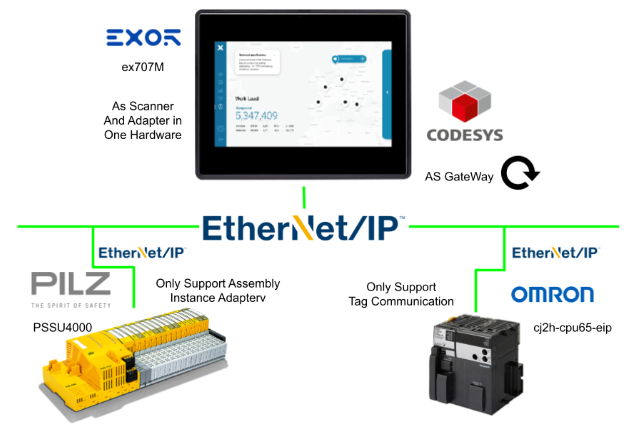
In this article, Pilz and OMRON PLCs are connected to different EXOR ex707M Ports, and Codesys is installed in the EXOR ex707M, with one communicating with OMRON on EthernetNet/IP Tag Link and the other on EthernetNet/IP Assemblies communication ,then EXOR will exchange the data taken from both as a Gateway.
let’s get started.
Reference Link
Configuration
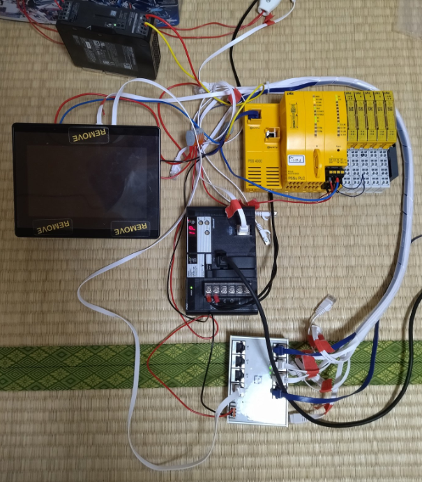
This is actually the Hardware Configuration in this article.
Implementation
Pilz Side
For detailed settings and programming techniques on the Pilz side, please refer to the Reference Link mentioned earlier.
IP Address
Set the IP address of the Pilz PSU4000 in Hardware Configuration>IP address.

Resources Global List
Define variables for the Ethernet/IP Adapter in the Resources Global List.

Program
The next step is to create a simple programme. The program will feedback the outputs of the data acquired via Ethernet/IP.

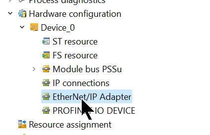
Ethenret/IP Setting
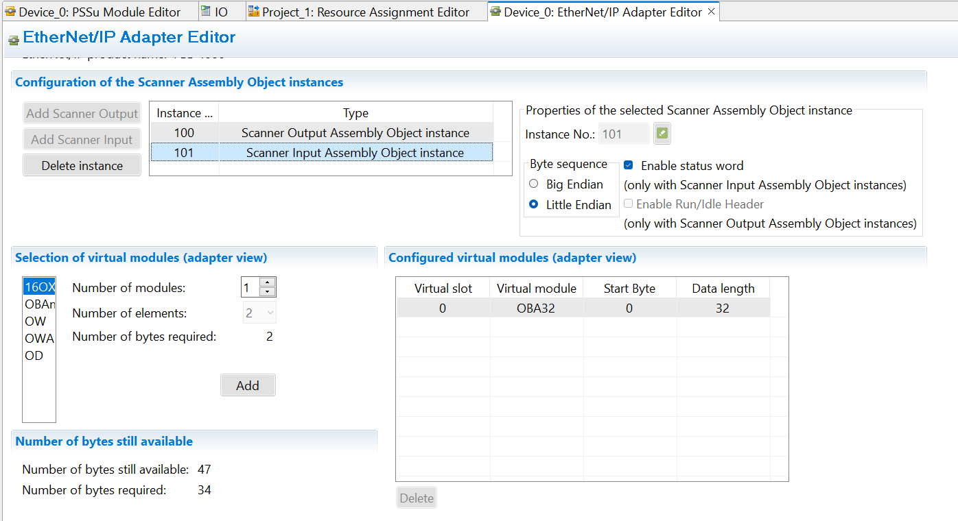
Let’s configure the Ethernet/IP Adapter.
Set the Scanner Output Assembly Object to 32 Bytes.

Set the Scanner Input Assembly Object to 32 Bytes.
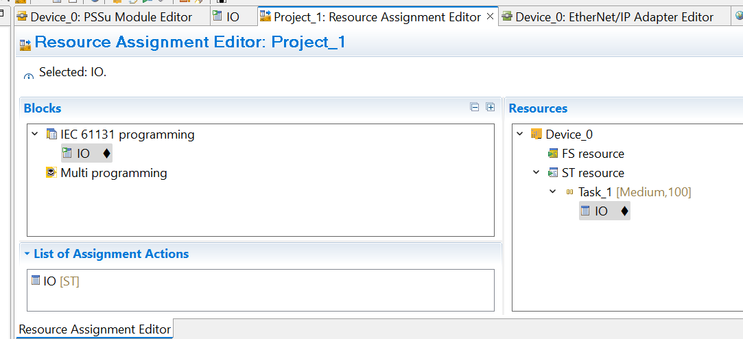
Mapping Program to Task
The next step is to assign the programme to a Task.
Codesys Side
This is the Codesys Version used in this article.

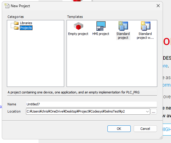
New Project
Create a new project under File>New Project.

Select Standard Project and proceed to OK.
Select Target
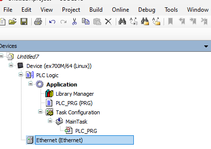
The next step is to set the Device Target for the relevant project.
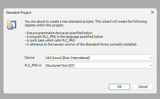
The ex707M from EXOR is used in this article, so select ex700M/64 from the Drop-List.

Done!The project has been created.
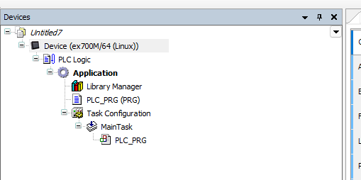
Scan Network
Next, go to Communication Settings>Scan Network to search for EXOR devices.

Done!You have searched for devices in the ex707M series. Click on the device.
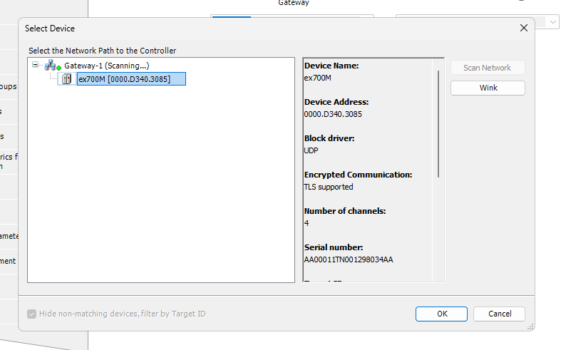
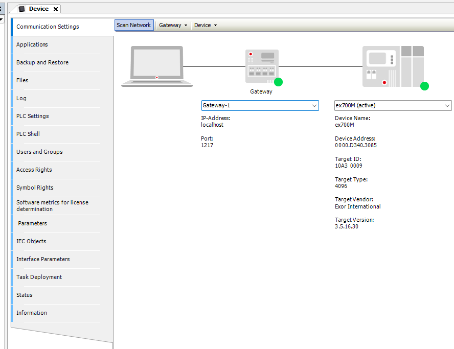
The connection between the Codesys IDE and the EXOR device has been established.
Add Ethernet Driver<Ethernet/IP Adapter>
Device Right-click>Add Device to add an Ethernet Driver.
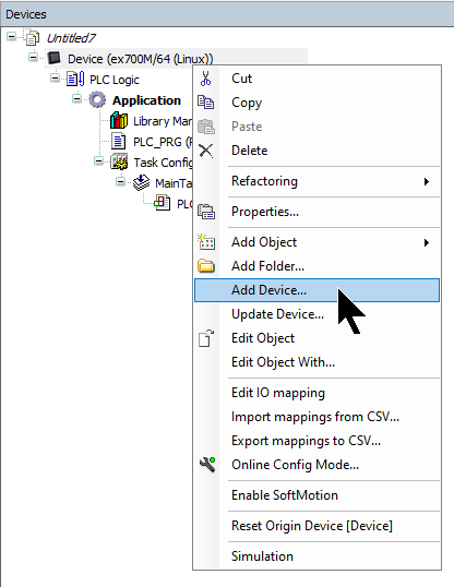
The Add Device screen is displayed.
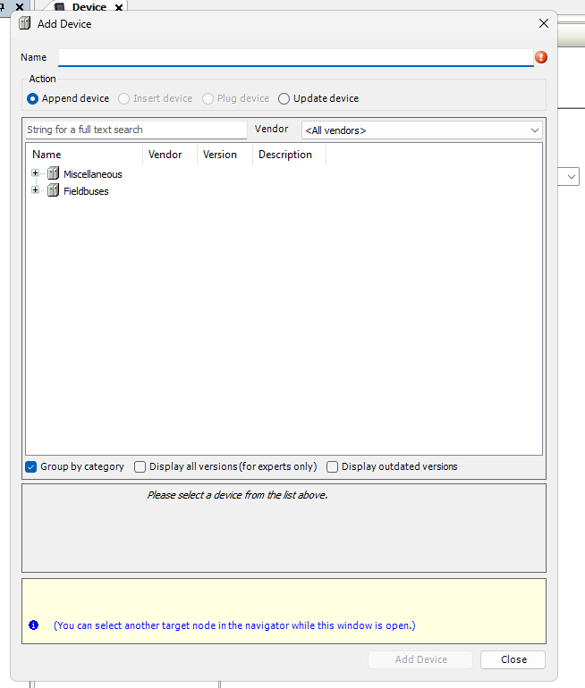
Add Ethernet Adapter>Ethernet.

Add Ethernet/IP Adapter
Next, select the Ethenret Driver and right-click>Add Device.
Select Fieldbus>EtherNet/IP>EtherNet Adapter and add with Add Device.
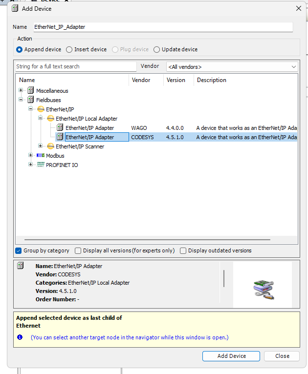
Done!

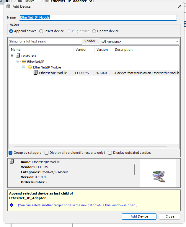
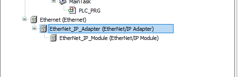
Add Ethernet/IP Module
Select Fieldbus>EtherNet/IP>EtherNet Adapter and add with Add Device.
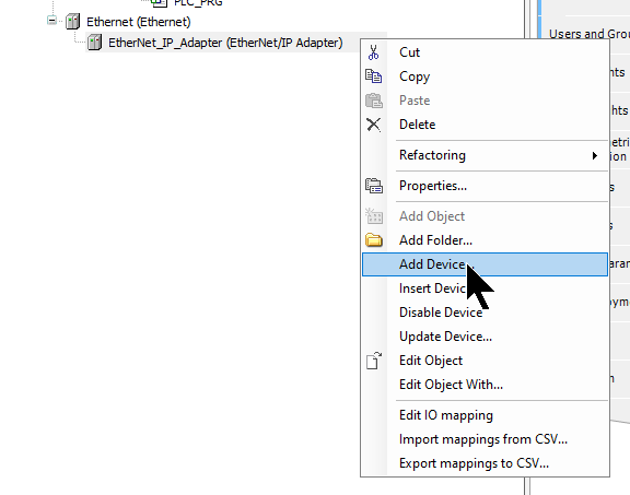
Select EthernetNet/IP Module and add it under Add Device.
Assemblies Configuration
Double-click on the Assemblies just added > Open the Assemblies screen. This is the Codesys EtherNet/IP Assemblies configuration screen.

O–>T
In the Comsuming Assembly section, click the Add button and add a new Assembly.
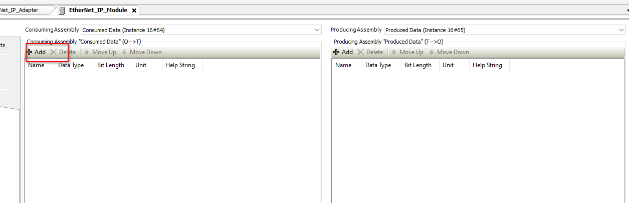
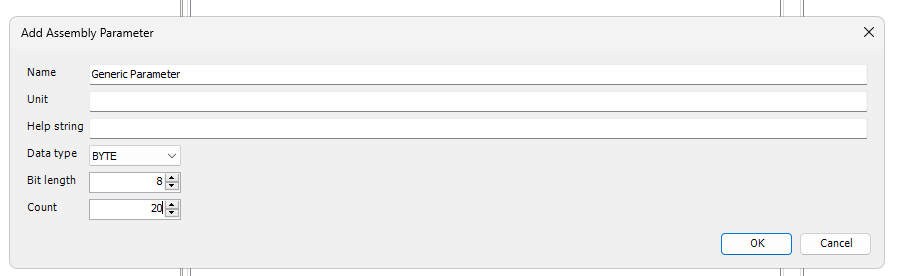
The screen changes to the Assembly Object configuration screen.

Set Data Type to BYTE and enter a Count of 20.
This means that the Assembly Object will occupy 20 Bytes of data.
Done!

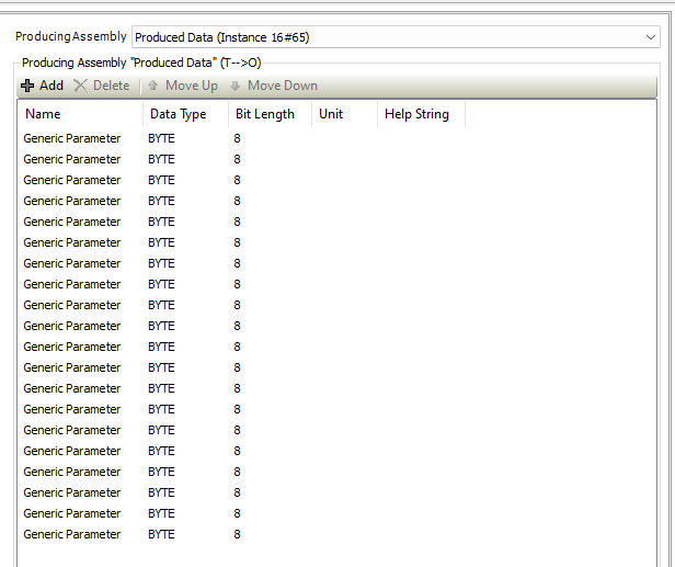
T–>O
Go to the Producing Assembly side with the same settings as before.
Export EDS File
The last step is to Export the EDS File of the EthernetNet/IP Adapter.
Export your EDS File under General>Export EDS File.

Add Ethernet Driver<Ethernet/IP Scanner>
Right-click>Add Device to add an Ethernet Driver.

Go to Ethernet Adapter>Ethernet.

Install EDS File
Next, click on Tools>Device Repository to install the EDS File for the Pilz PSS 4000 on the Codesys side.

Click Install and install the EDS File downloaded from the Pilz HP.

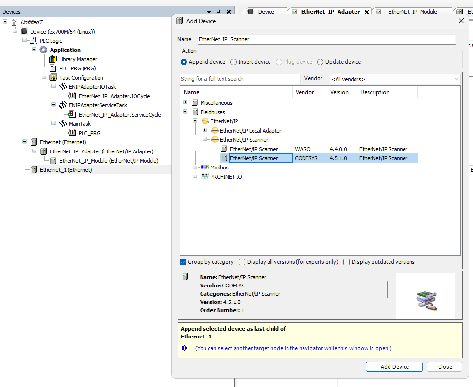
Add Ethernet/IP Scanner
Next, select the Ethenret Driver and right-click>Add Device.
Add Pilz PSS 4000.
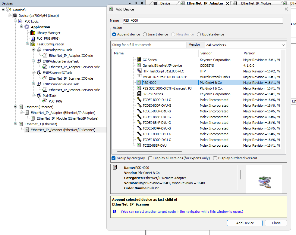
Done!

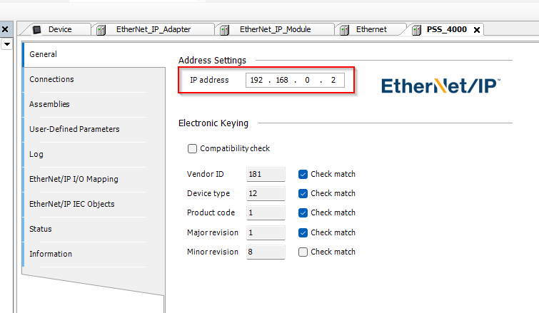
Configure the IP
Double-click the PSS 4000 you have just added and use the Tab in General to set the IP address.
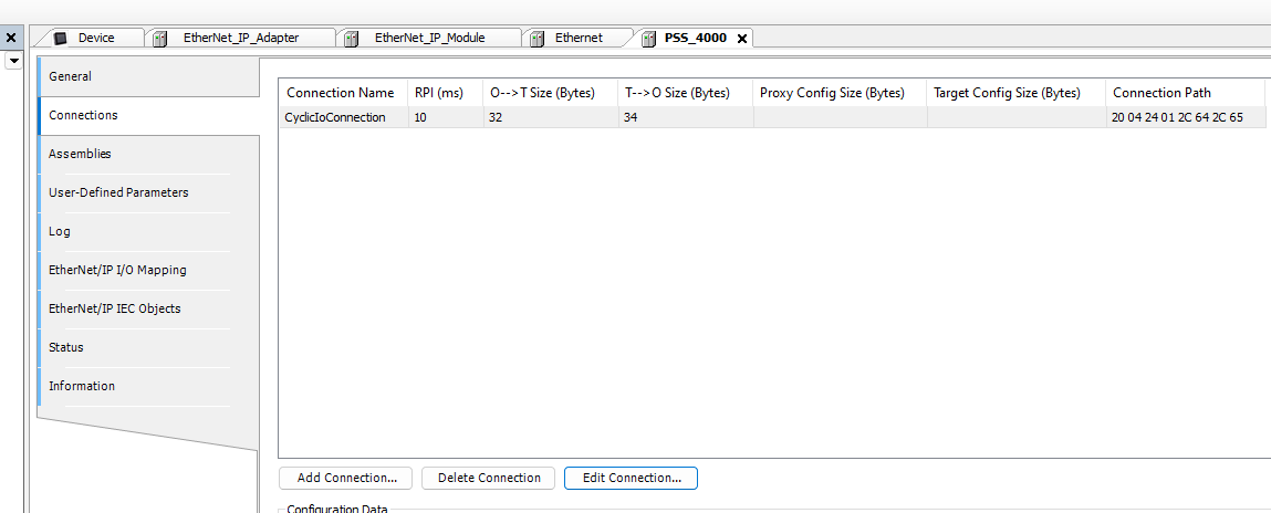
Edit Connection
Next, open the Connections Tab and click on Edit Connection.

This is the Codesys EthernetNet/IP connection configuration screen.
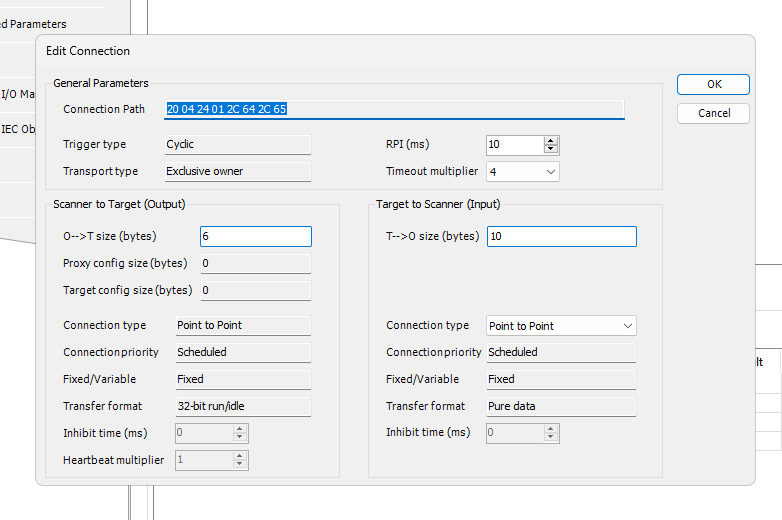
Set O–>T Size and T–>O Size to match Pilz’s PSS 4000 project.

Done!
Add GVL
Now open Application>Right click>Add Object>Global Variable List to add a Global Variable List.
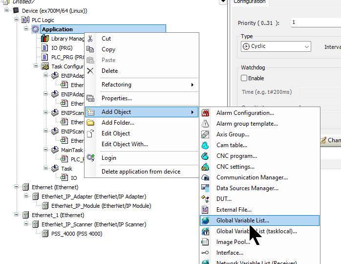
Enter a GVL name.

Define variables for Mapping on the OMRON and Pilz side.
| {attribute ‘qualified_only’} VAR_GLOBAL OMRONInByts,PilzInBytes:ARRAY[0..32]OF BYTE; OMRONOutBytes,PilzOutBytes:ARRAY[0..32]OF BYTE; END_VAR |
Add POU
Now I will program the IO data to work as a GATEWAY function.
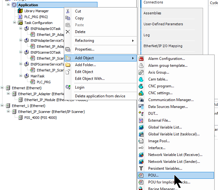
Enter a POU name and create a POU.

Here is the program.
| MEM.MemMove( pSource:=ADR(GVL_1.OMRONInByts) ,pDestination:=ADR(GVL_1.PilzOutBytes) ,uiNumberOfBytes:=SIZEOF(GVL_1.OMRONInByts) ); MEM.MemMove( pSource:=ADR(GVL_1.PilzInBytes) ,pDestination:=ADR(GVL_1.OMRONOutBytes) ,uiNumberOfBytes:=SIZEOF(GVL_1.OMRONInByts) ) ; |
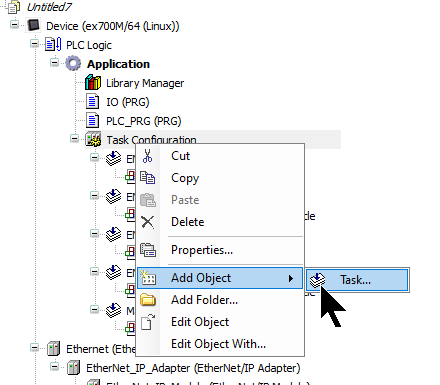
Add Task
To add a Task to be executed at high speed, click Task Configuration >Add Object >Task.
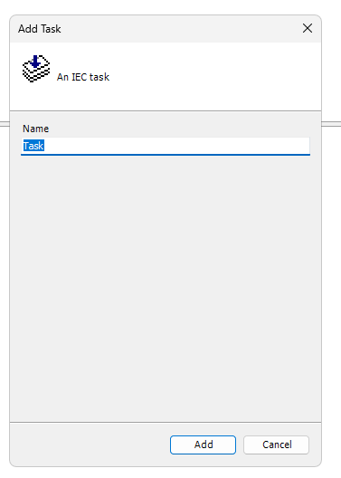
Enter a task name.
Configure Task
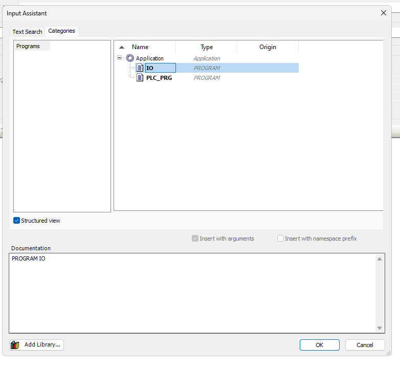
Set the Cycle Time of the Task in Interval and click the “Add Call” button.

Choose the POU you just added.
So POU IO will run in 1 ms.

Download
Finally, download the project to Runtime. we completed the Codesys side.

OMRON CJ Side
Now we will configure the Omron Side.
Configure EIP
Open CX-programer and perform Hardware Configuration in IO Table and Unit Setup.

Ip address
Click Build-in Port/Inner Board>CJ2B-EIP21.

Set the IP address to match your application.

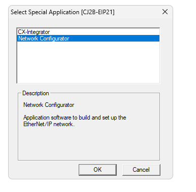
Start Network Configurator
Next, to build the EthernetNet/IP network, right click on CJ2B-EIP21>Start Special Application>Start with Settings Inherited.

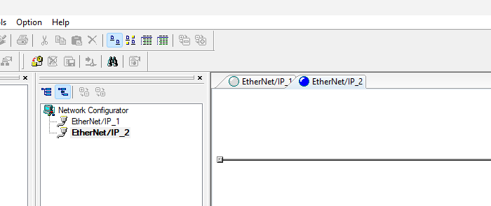
Start the Network Configurator.
Done!

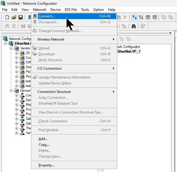
Connect
Connect USB or Ethernet with PC and CPU, then click Network>Connect.
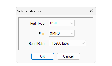
Set the connection Interface. This time, we will use the USB Interface.
Go to BackPlane>CJ2B-EIP21>Configure the connection Interface for TCP-2.
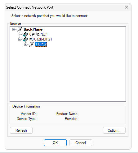
Set Use the existing network and proceed with Ok.

Done!
Upload
To upload the Configuration currently inside the CPU, right-click on an empty space in the Network Configurator > Upload.

Proceed with Yes.

Select the EthernetNet/IP device you wish to Upload.

Done!CJ2B-EIP21 has been Uploaded.

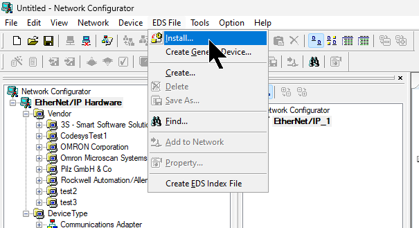
Install EDS File
Go to EDS File>Install to install Codesys EDS File into Network Configurator.
Select the EDS File you just exported in Codesys IDE.
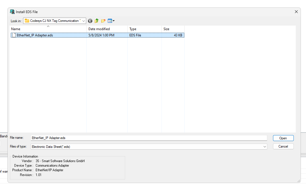
Done!
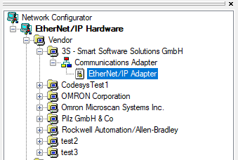
Add to Ethernet/IP Network
Double-click the EthernetNet/IP Module in Codesys to add it to the EthernetNet/IP network.
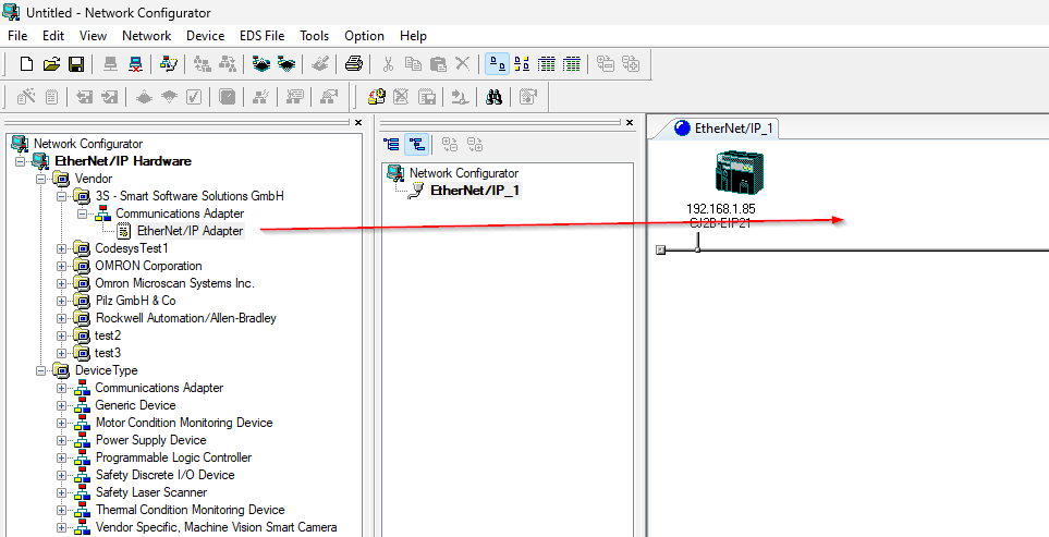
Done!Codesys’ EthernetNet/IP Adapter has been added.

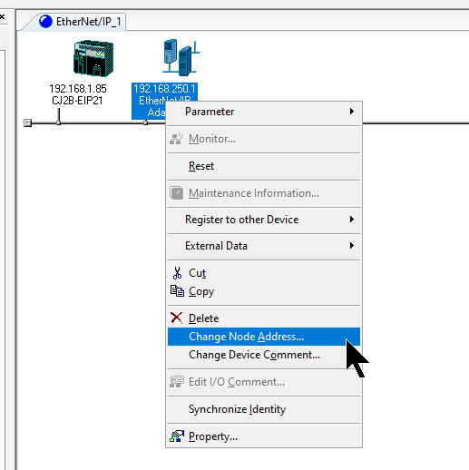
Change IP
Right click on the device you just added>Change Node Address to change the IP address.
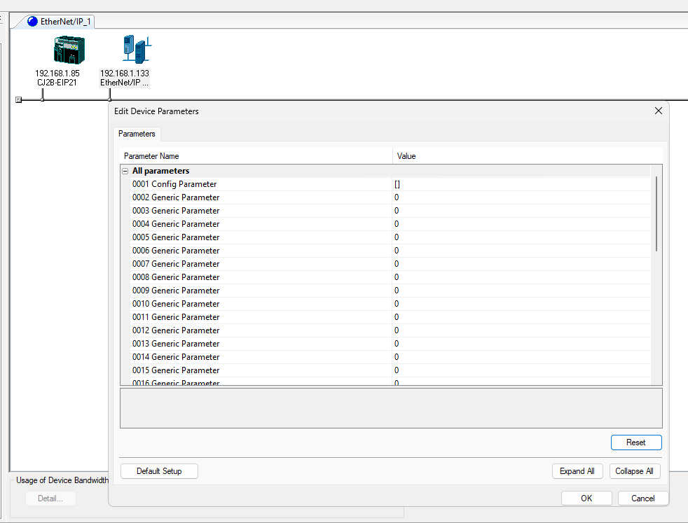
Change the IP address to match your application.

Configure Tags
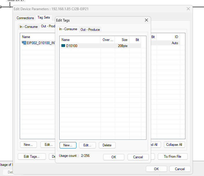
Double click on the Codesys EthernetNet/IP Adapter imported from the EDS File and you will find the IO data you have just configured in the Codesys IDE.
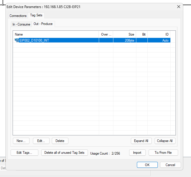
Next, double-click CJ2B-EIP21, open the Tag Sets tab, and add a communication Tag.
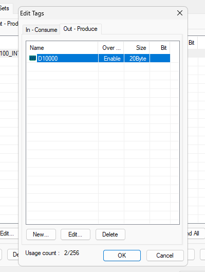
Click Edit Tags.
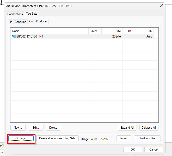
From this screen, you can add or change a Tag.
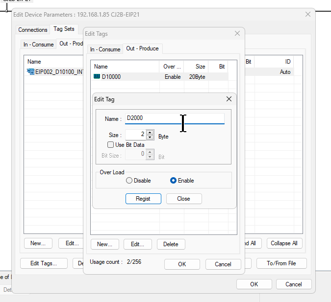
Click “New” to add a new Tag.
Enter an OMRON CPU device, such as D, in the Name field, and link it to the actual Tag and OMRON Memory.
In the example below, the tag is linked from D2000 to 2Bytes, i.e., D2001.
In this case, we will link 20Bytes of data and Tag from D10100.
Configure Connections
The next step is to set up the Tag communication connection for Codesys<–>OMRON CJ2B-EIP21.When you open the Connections tab, the Unregister Device List should show the Codesys device you just registered.
Select that device>click the down arrow.
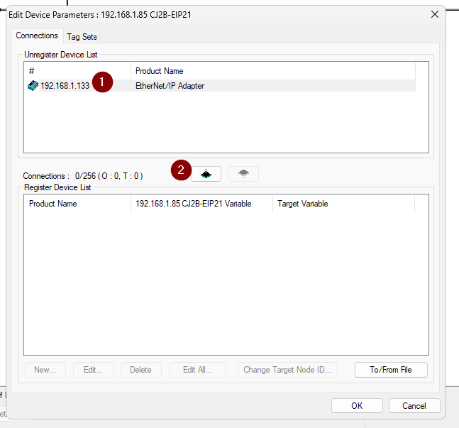
Done!We configured the connection between CJ2B-EIP21 and Codesys.

Next, click New to add a Tag Connection to communicate between the two devices.

The Adapter Edit Connection screen appears.
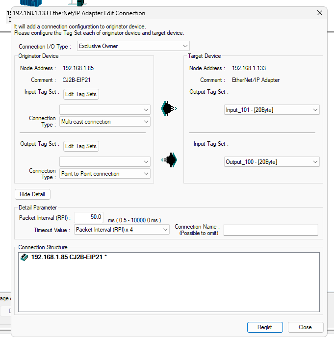
Connection I/O Type
Set the Connection I/O Type to match your application.
In this example, we will set the connection as Exclusive Owner.

Input Tag Set
The next step is to set the Input Tag Set.

Done!

Output Tag Set
Set the Output Tag in the same way.

Done!
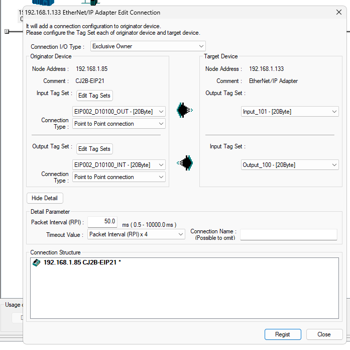
Result
As shown in the figure below, we have set up a Connection for Tag communication between CJ2B-EIP21 and Codesys.

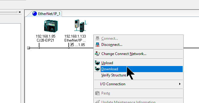
Download
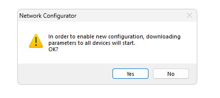
Finally, download the Network Configuration to the CPU.
Proceed with Yes.
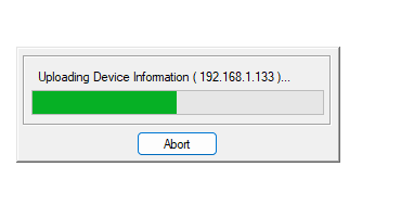
Wait a while…
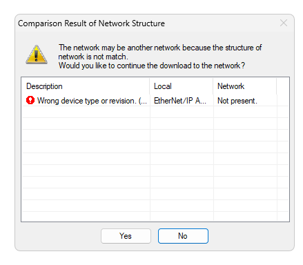
Ignore the error.
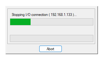
Switch to Program mode and download Configuration.

Wait a while…
Result
Done!Codesys and CJ2B-EIP21 communicate CIP I/O.

Next, let’s check the D memory from the CX-Programmer.
Click PLC>Edit>Memory.
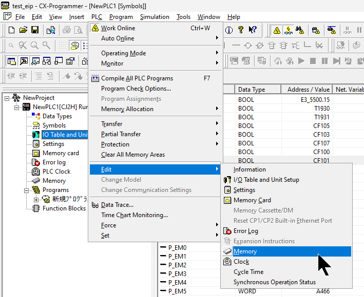
This is the screen for monitoring PLC Memory and you can check the input/output data.

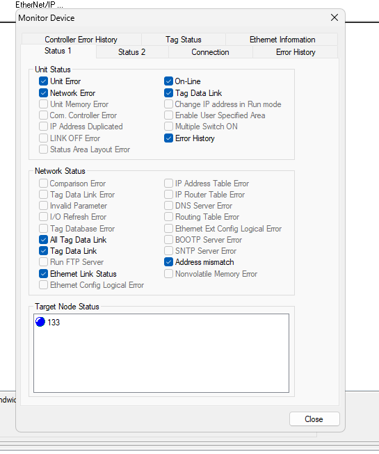
Now let’s check the status of the CJ2B-EIP21 from the Network Configurator.
Go to CJ2B-EIP21>Right click>Monitor.

133=192.168.1.133=Codesys IP address and we have confirmed that communication with Codesys is currently normal.
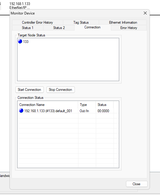
You can also check the communication status on the Connection Tab.
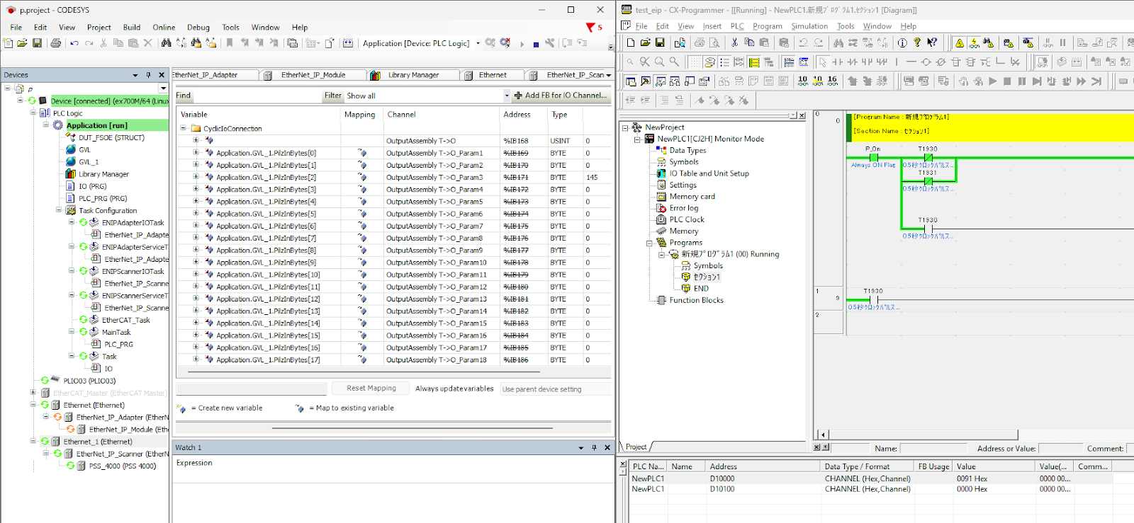
As shown in the figure below, data written from OMRON is also reflected on the Pilz side.
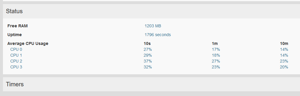
EXORのHMI側ではCodesysのStackを入れたら、大体20%のCPU使用量になります。