This is the third episode of the Pilz PSS4000 introduction. In the previous episode, we introduced the creation of ST Resource programs and simple tool operation. Next, I would like to explain Pilz’s main PLC Concept and show you how to make a simple PLC Program, but also the hardware configuration.
Thanks!
PSSu H PLC1 FS SN SD is borrowed from Pilz Japan, Thanks !!
PILZ
PILZ supports FA sites as a total solution supplier with safety and automation technology solutions, guaranteeing not only human safety, but also machine and environmental safety, to ensure the safe operation of machines and equipment. Pilz has 42 local companies and branches worldwide and is active in various fields such as packaging, the automotive industry, robotics applications, as well as wind power and railway technology.

Office:
ピルツジャパン株式会社
〒222-0033
横浜市港北区新横浜3-17-5
いちご新横浜ビル 4階
HP
Reterence Link
Data types
Pilz CPUs, like other manufacturers, variables must always declare their data type by declaring the data type in the Pilz CPU,
- Limit the range of variables (e.g. USINT/INT)
- The application area that can be used is also divided (FS/ST Resource).
- Memory area occupied by data types
Note that FS Data Type variables cannot be used in ST Resource.
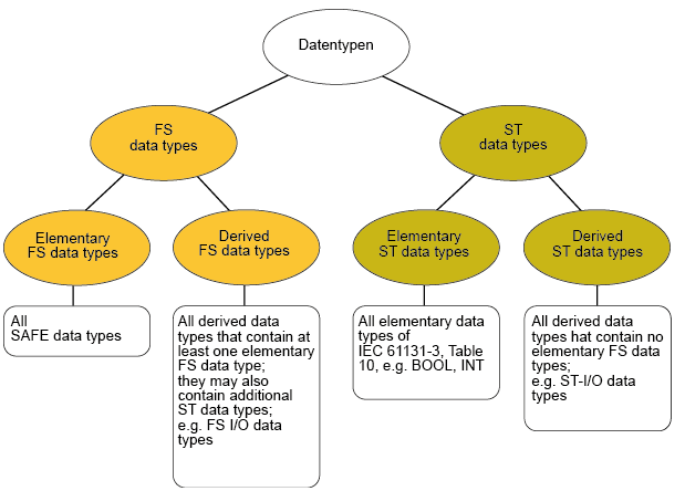
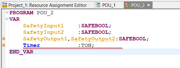
FS data types
This is the FS Data Type of the Pilz CPU and is the variable type used in the Safety application. Note that once a variable is defined in the FS Data Type, it can only be used in FS Resource.
- SAFEBOOL
- SAFEBYTE
- SAFEWORD
- SAFEDWORD
- SAFELWORD
- SAFESINT
- SAFEDINT
- SAFELINT
- SAFESINT
- SAFEYUINT
- SAFEUDINT
- SAFEULINT
Also, a minor detail,
- FS Data Type variables can also be used in ST Data Type functions. For example, if a Function block requires a BOOL variable parameter, it is OK to use SAFETBOOL, and the BYTE_TO_WORD IEC program conversion function can also be used for SAFEBYTE_TO_SAFEWORD.
- FS Data Types variables are OK with expressions like SAFE#47 to update new value.
IEC61131-3
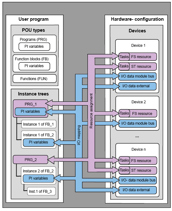
In IEC61131 Programming as well as Pilz, there are three types of POUs in the User Program. PRGs (Programs) were used in the previous and current articles, but there are still FBs (Function Blocks) and Functions (FCs), and FBs are called in PRGs in structured programs (note that the depth of multi-calls can be up to 12 times, and that regression is not allowed). I will introduce it again in a future issue.
This is a programming process, but it can be reused many times in a PRG by creating Function Blocks and Functions.
FunctionBlock
“Instance” is an item in the Flow, and its purpose is to reserve memory in the CPU so that the results of the corresponding FB operations can be recorded.
Instance is only memory, and what is important is the Function Block. Using a car analogy, the Function Block is the blueprint of the car, and the Instance is the car built according to that blueprint.
Function
Unlike Function Block, Function does not require memory allocation from Instance. Instead, the result of the operation does not remain in the next cycle.
PI variables
PI variables can be defined in PRG, FC, and FB, which can be used to access hardware IO data as well as to exchange data between POUs.
I-PI Variables
Variables here are transferred from I-Data in the Modules Bus (e.g. Hardware-Input) to external I-Data or O-PI Variables in other POUs.
Statement
<Variable name >AT %i* <Data Type>;
| ESTOP Input1 AT %i*:BOOL; |
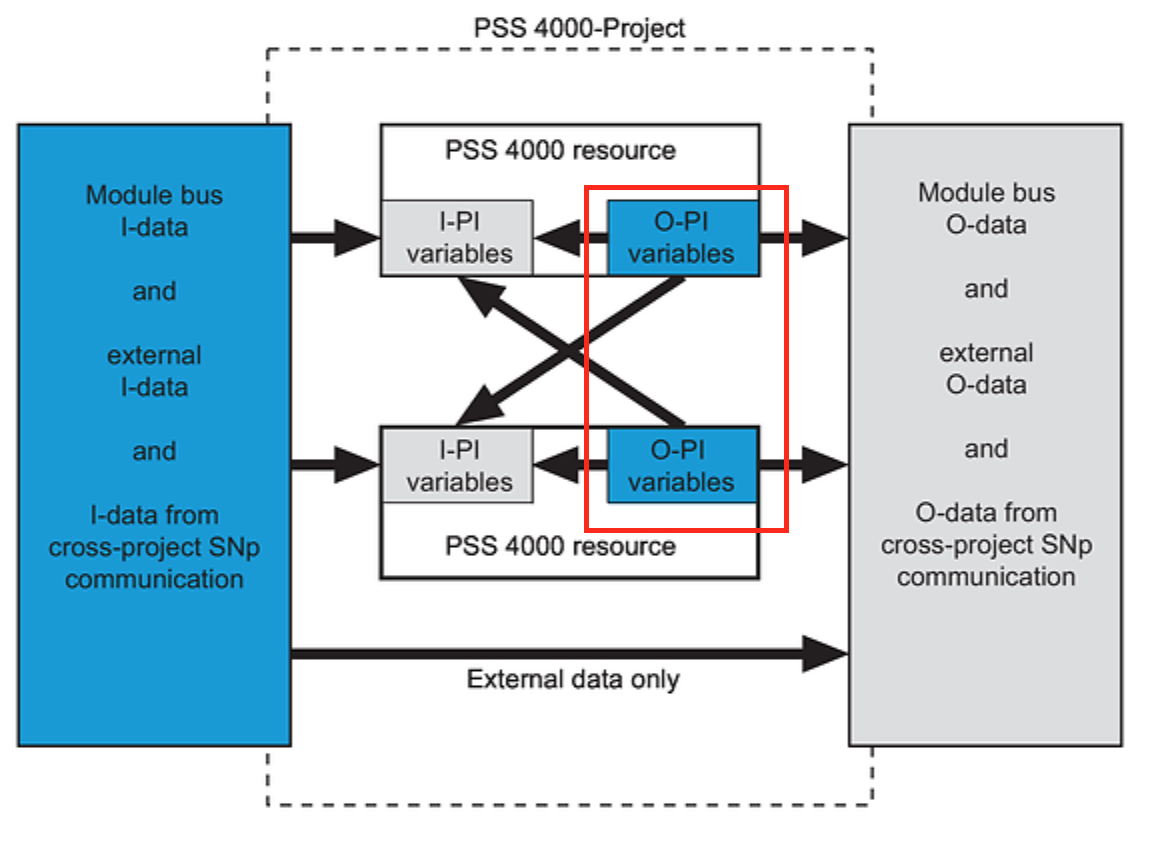
O-PI Variables
Variables here are transferred from O-Data (e.g. Hardware-Output) in the Modules Bus to external O-Data or I-PI Variables in other POUs.
Statement
<Variable name >AT %Q* <Data Type>;
| ESTOP Input1 AT %Q*:BOOL; |
Resource assignment
In the last Tutorial, you assigned ST Resource to Tasks from Resource Assignment. The Resource Assignment is used to set what kind of program is to be executed on what kind of Tasks, and will be assigned to Tasks after the program is completed.
As an additional note, POU can be a Period, Event-Base, or Free Trigger.
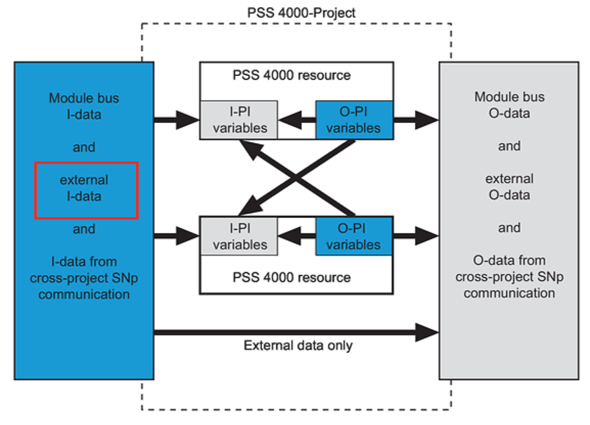
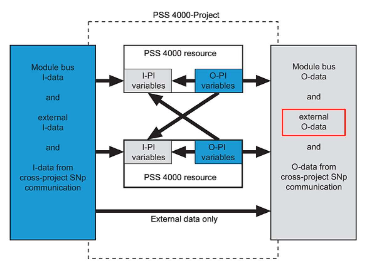
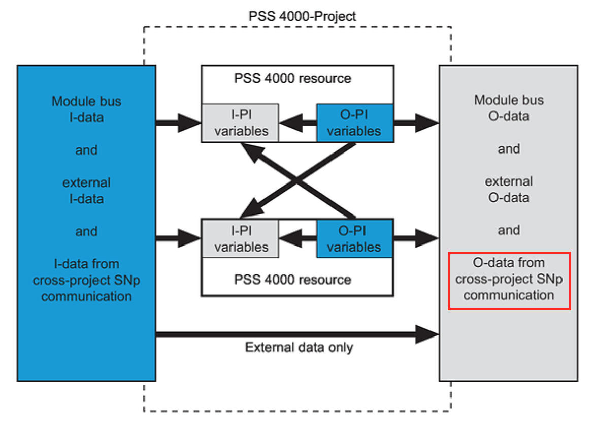
Validity of process data
The data flow here describes the flow of the Data Source and Data Sink. When transferring data from the blue area (Data Source) to the gray area (Data Sink), there is always a communication error. If Valid=False, the Data Source is invalid or the Data Source is not accessible.If Valid=True, the Data Source is valid.
A Valid Bit of False can have various causes, for example
- input error, I/O module error, Module Bus error, and starting in Module bus I-Data
- communication is stopped or an error has occurred in External I -data
- Task and Resource are in Stop state in O-Pi variables

Module bus I-data
This is the input data from the FS/ST module Bus.
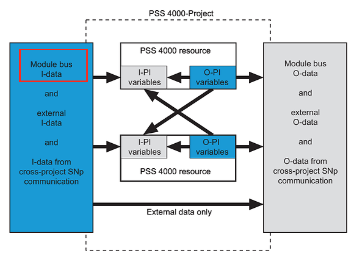
External I-data
It will be input data from external communication (e.g. PROFIBUS-DP).
O-PI variables
O-PI Variables come from the PSS 4000 Resource. (ST Resource or FS Resource)
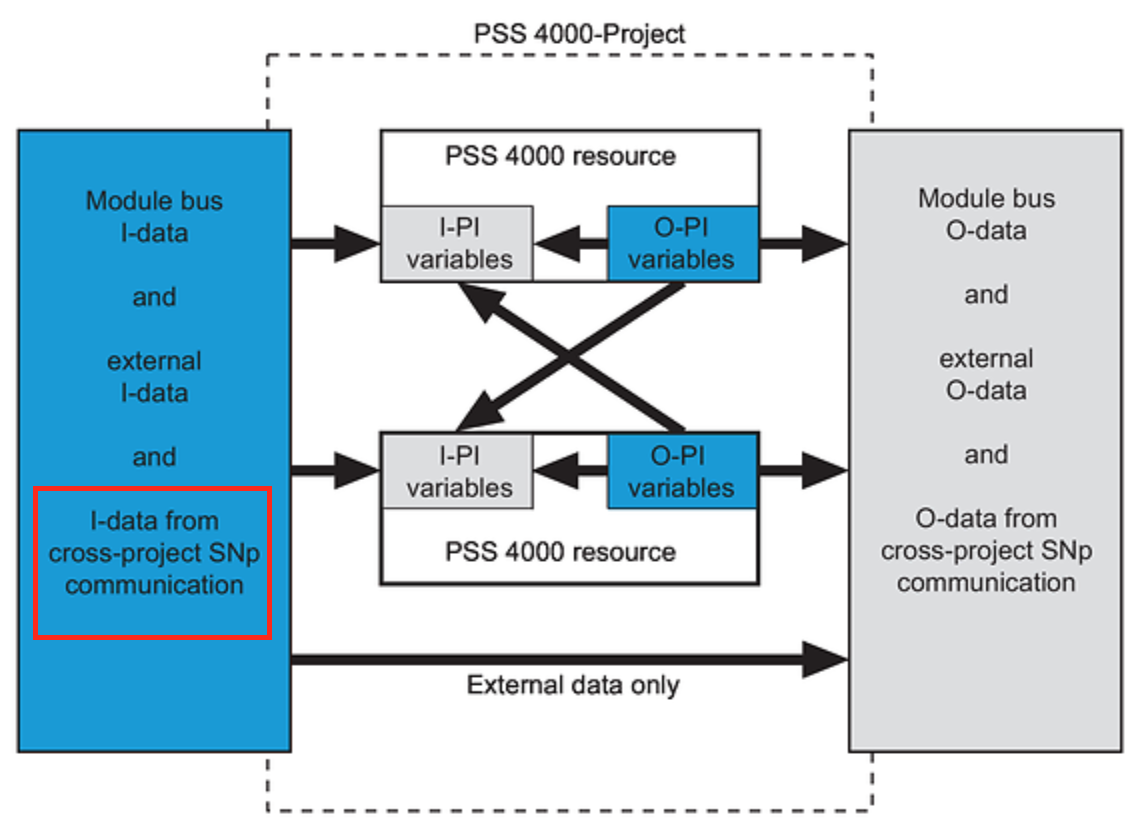
I-data from cross-project SNp Communication
Output data from PSS 4000 project. (e.g. O-PI variables)
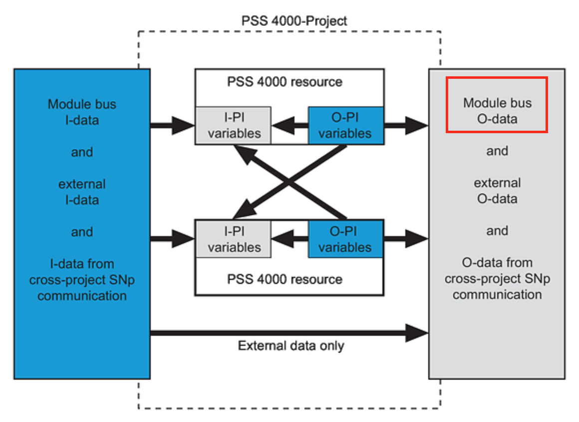
Module bus O-data
This is the output data of writing to the FS/ST module Bus.
External O-data
The data will be output to external communication (e.g. PROFIBUS-DP).
I-PI variables
I-PI Variables come from PSS 4000 Resource. (ST Resource and FS Resource)

O-data from cross-project SNp Communication
Input data from PSS 4000 project. (e.g. O-PI variables)
Add Safety IO Modules
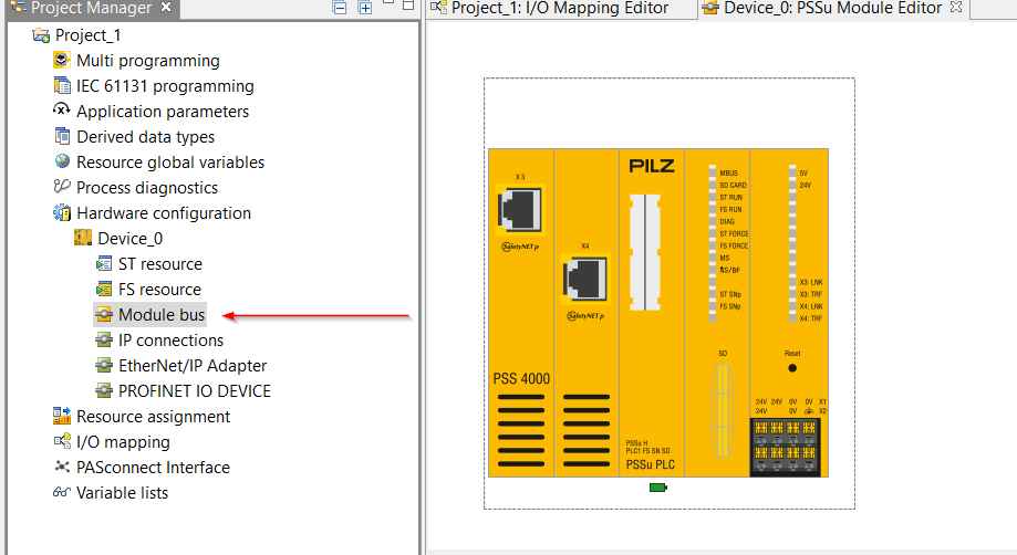
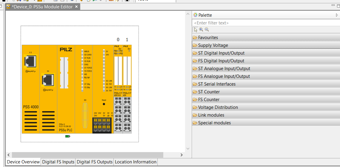
First, add the I/O Module from the project.
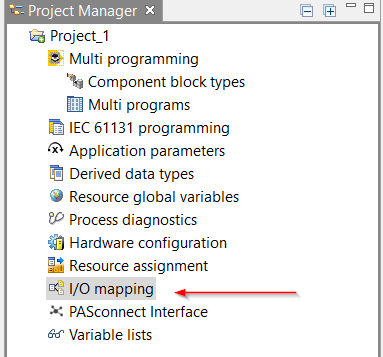
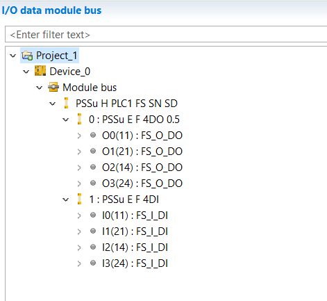
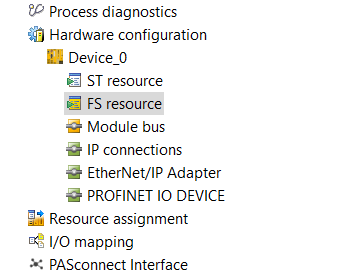
Click Hardware Configuration>Device_Name>Module bus.
PSSu E F 4DO 0.5
Find PSSu E F 4DO 0.5 from Palette on the right and Drop PSSu E F 4DO 0.5 to the CPU.
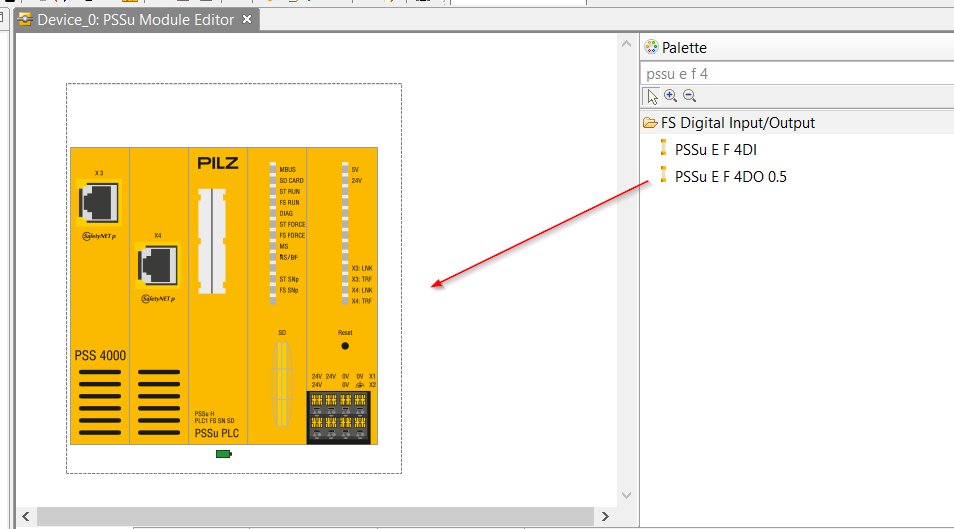
Just lke this.

PSSu E F 4DI
Find PSSu E F 4DI from Palette on the right and drop PSSu E F 4DO 0.5 into the CPU.
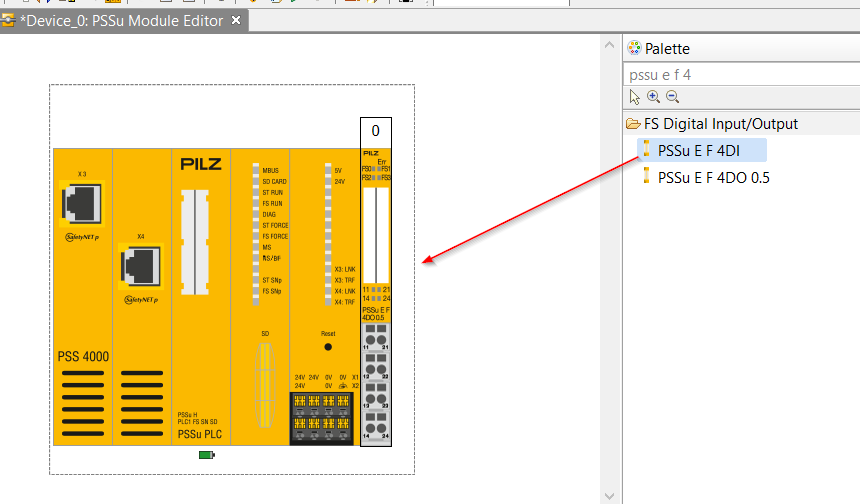
Just like this.

So the Hardware Configuration build is complete.
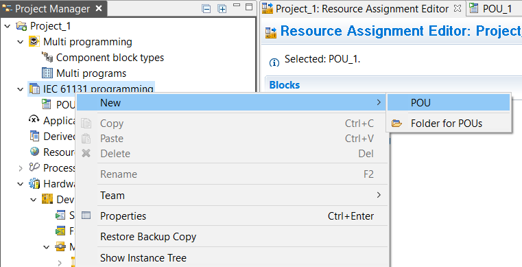
Add Safety Program
We will now create a Safety program, right click on IEC 61131 programming>New>POU to create a new POU.
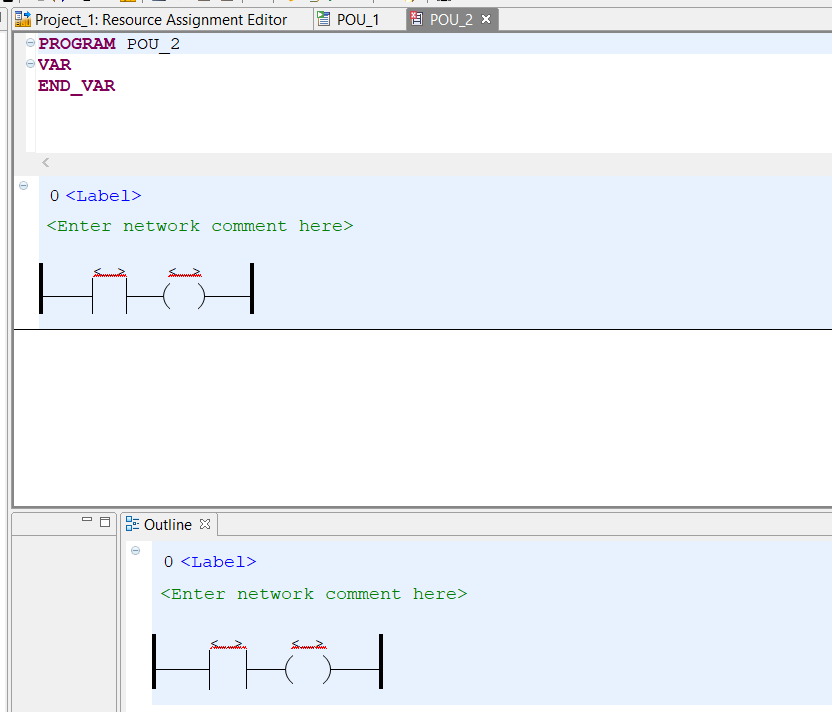
Select Programming Language as LD (Ladder) and Type as Program.
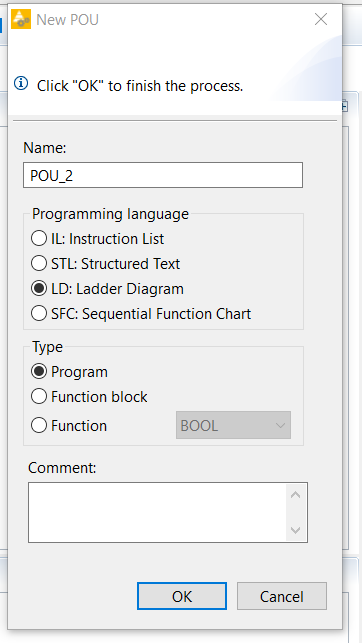
The IDE screen for the Ladder program is now displayed.
Define Safety Process I/O
First, we will define the Safety Process I/O.
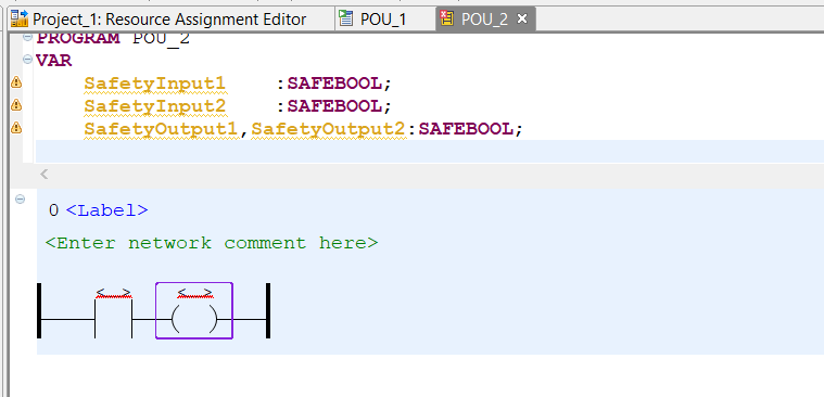
Programming
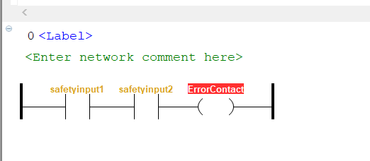
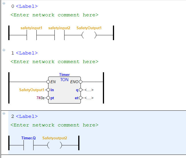
Network1
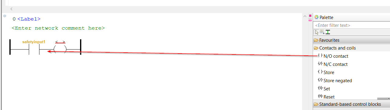
Click on the NO contact .
You can assign devices to contacts like this.

Add another contact to the Network. You will find Palette>Contacts and coils>N/O contact on the right.

Add the NO Contact into your network
Just liket this.

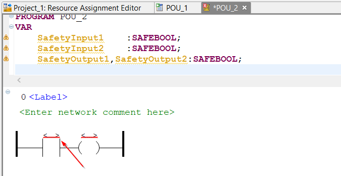
If an undefined variable is entered into a contact, it will turn red.
Done!

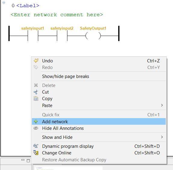
Network2
Right click on the white part of the IDE>Add Network to add a new Network.
Search for TON (Delay ON) from Palette, and then Drop to Network2.
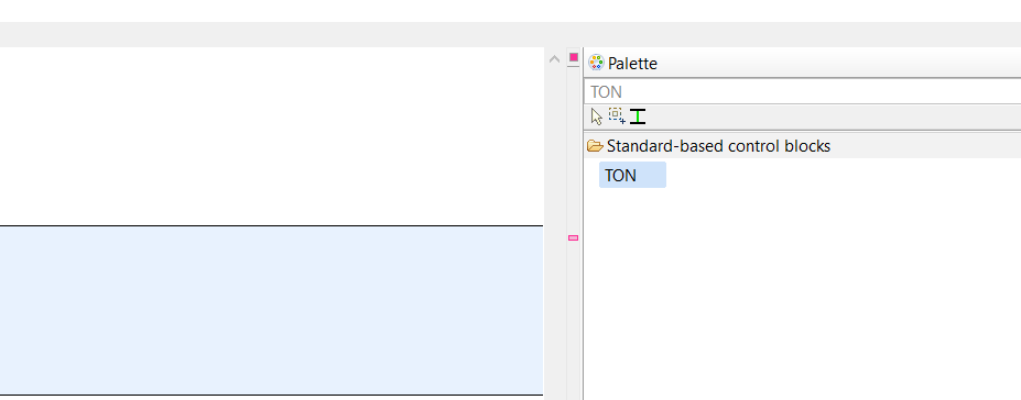
TON Function Block has been added.
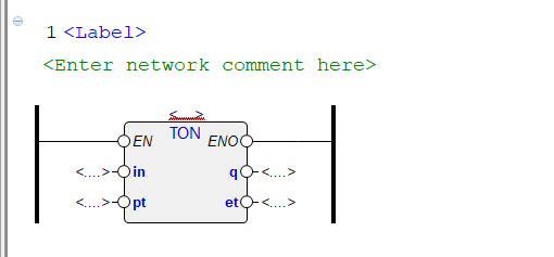
Defines the TON Instance.
The <> portion of the Function Block is the Field where the Instance is entered.
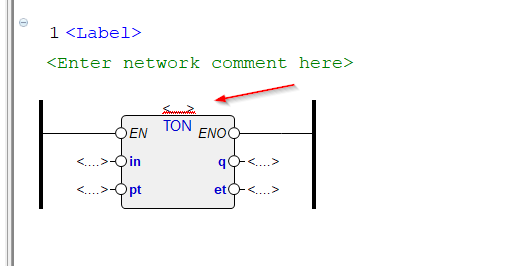
Use these operations to enter the TON Instance.

Network3
Finally, add another Network to output another Coil when the Delay Timer’s Q (output) is set to True.
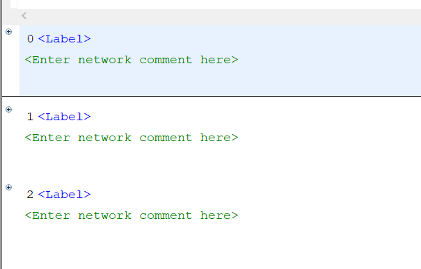
Comment
The green text area allows you to enter Comments and a brief description for each Network.
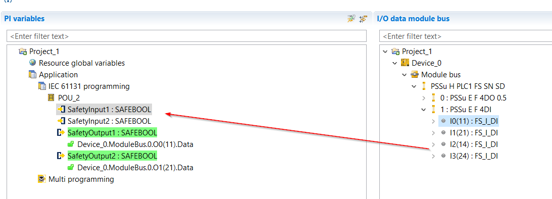
IO Mapping
From IO Mapping, you can map the FDO/FDI and User program that you have just added.
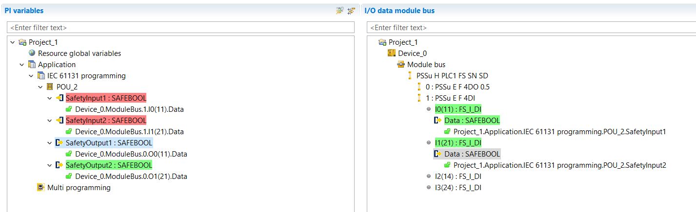
PI Variables and I/O Data Module buses can be mapped from the Mapping screen.

Hardware Configuration already has multiple inputs and outputs.
Simply select the output of the module, and then plug it directly into the FS Resource and the variable you want to map.
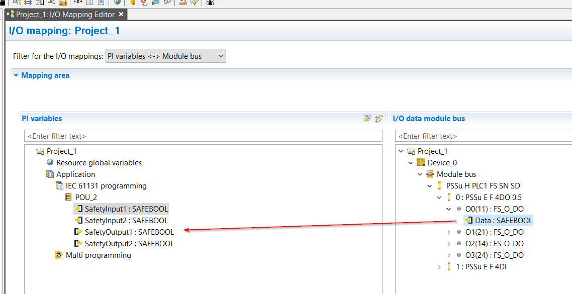
The PI Variables and I/O Data output section is now complete with Mapping.
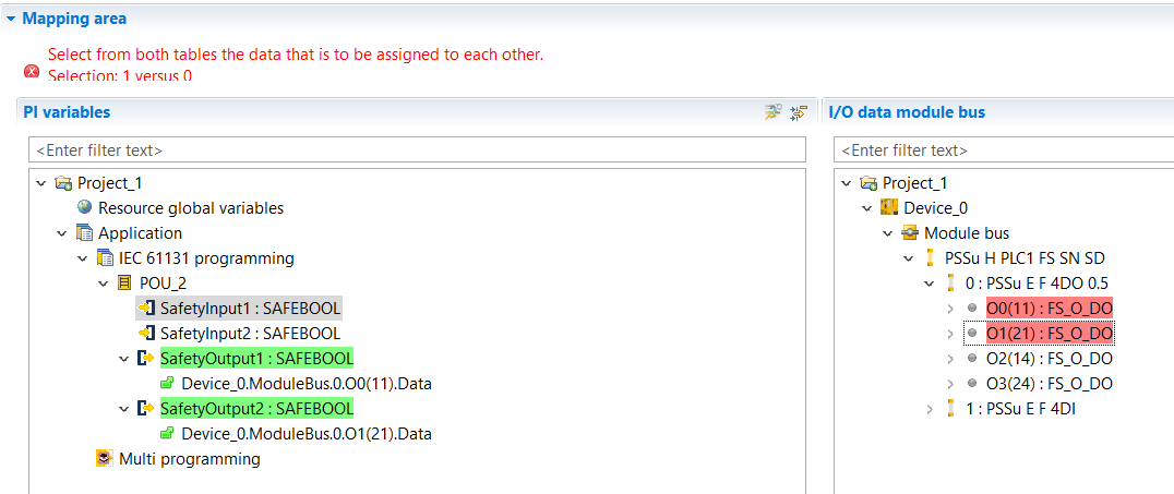
For the safety input, similarly, you can select the output of the module, and then just plug it directly into the FS Resource and the variable you want to map.
Done!
Add FS Source
Add Safety program to FS Resource.
Drop the Safety Program you just created into FS Resource.
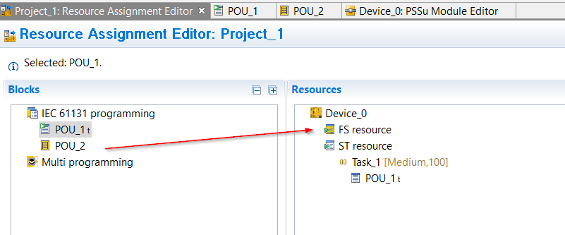
Just like this.

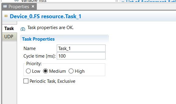
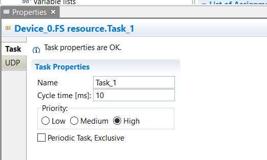
Configure Task
Now we can Set the Task settings for FS Resource. The Cycle Time and Priority cannot be set for the previous standard task, but they can be set for FS Resource.
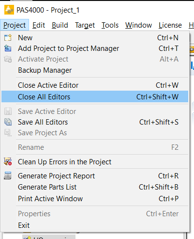
Compile
Close all Editors once with Project>Close All Editors.
Next, compile the project by going to Build>Build All.
Then Download the Project to the CPU.
