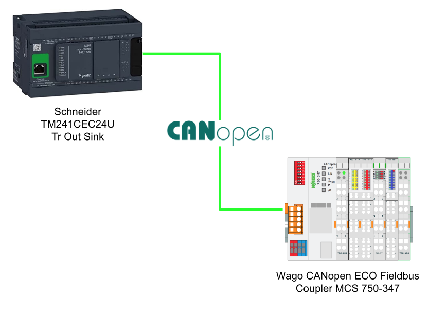
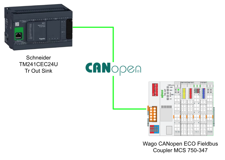
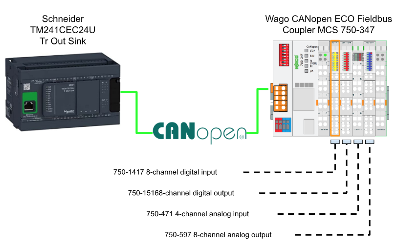
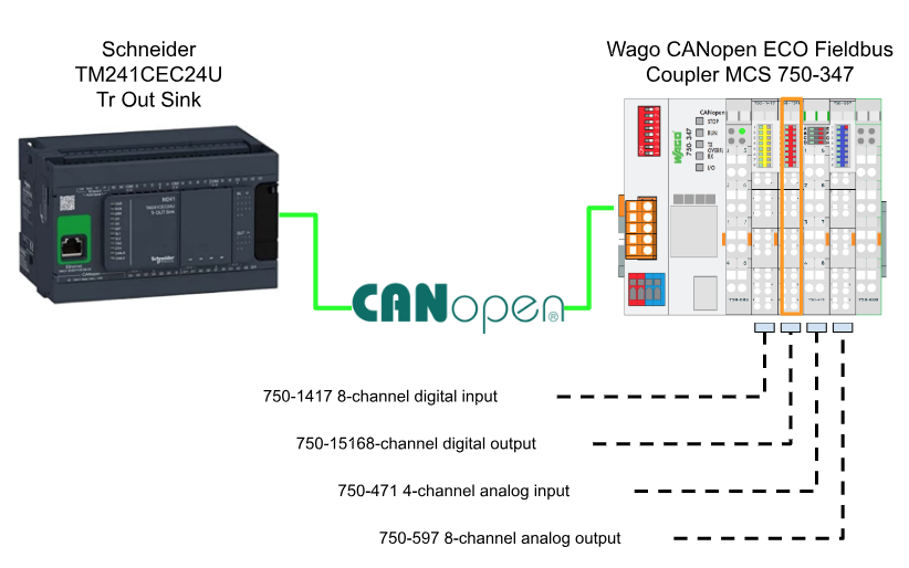
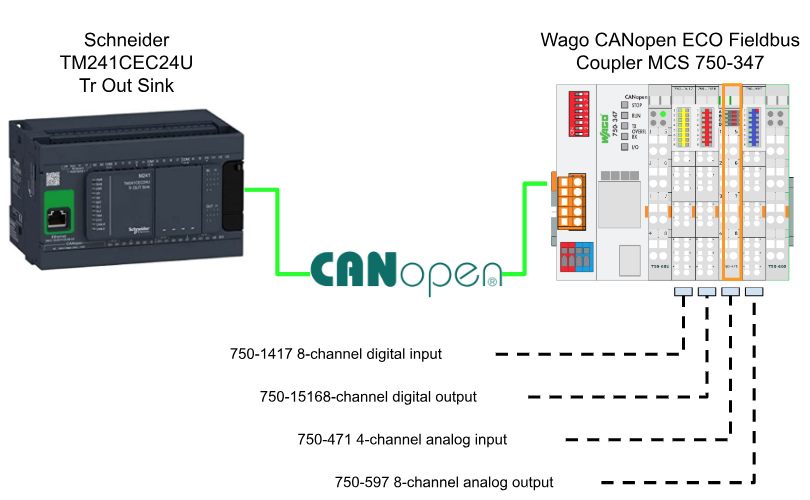
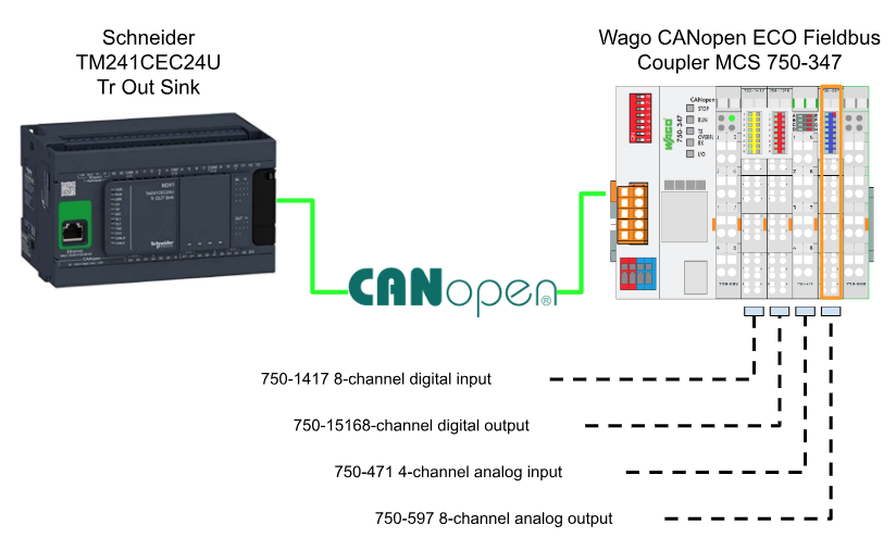
This article builds a CANOPEN network using Wago CANOPEN Fieldbus Coupler and Schneider’s TM241ECE24U CPU. Schneider is Master and Coupler is Slave. thank you!
Thanks!
I would like to thank Wago Japan Co., Ltd. that lent the device to me to write this post.
Wago Japan
CANOPEN Coupler750-347 was lent by Wago Japan Co., Ltd. WAGO was established in 1951, and has supported the field with the technologies of PUSH WIRE and CAGE CLAMP, which have contributed to industries around the world with terminal block technology. WAGO also has a PLC LINEUP, offering automation solutions with an emphasis on openness and flexibility.
Wago Japan Co., Ltd. is headquartered in Koto-ku, Tokyo.

750-347
Here is the coupler that we are using in this tutorial.

Power Supply
DC24 V is used for the power supply, Red is + and blue is – side.
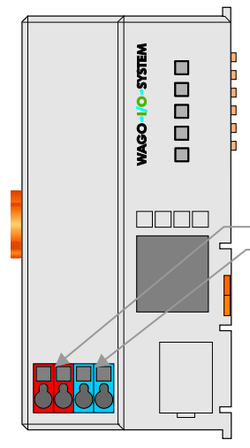
Layout
Here is the Layout of 750-374 coupler.

LED
There is a LED on the 750-354 CANOPEN Coupler to indicate the status of your Module.

| LED | Color | Description |
| STOP | Red | Coupler is in Stop |
| RUN | Green | Coupler is running |
| TX OVERFL | Red | CAN Data Sending Buffer is Overflow |
| RX OVERFL | Red | CAN Data Receiving Buffer is Overflow |
| I/O | Green/Red/Orange | The Actual status of I/O |
Fieldbus Connector
Here is the wiring of the 750-347 Fieldbus Connector.
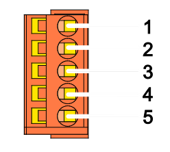
| Pin | Signal | Description |
| 1 | N.C | Reserved |
| 2 | CAN_H | CAN_H Bus Line |
| 3 | Drain Shield | CAN shield(Optional) |
| 4 | CAN_L | CAN_L Bus Line |
| 5 | GUD | CAN Ground |
Address switch
A red DIP switch on the Coupler can set the Node-ID.
For example, if 1 and 2 are also ON, the Node-ID of this coupler will be 3.
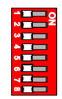
Baud Rate Setting
This DIP switch can also set the Baud Rate.
First, turn on the power to the coupler with all DIP switches turned off, and put the coupler in configuration mode. After waiting for a while, four LEDs will display the current Baud Rate on STOP(Switch1), RUN(Switch2), TX Overflow(Switch3) and RX Overflow(Switch4). And you can change the Baud rate by changing the DIP switch. Finally, turn the switch 8 to ON to apply the settings.

Communication Object support
The 750-347 supports the following Communication Objects.
- 5 Tx-PDOs
Input Data - 5 Rx-PODs
Output Data - 2 Server SDOs
Node StateのConfigurationデータ - SYNC
- Network management Objects
Module Control Protocols
Error Control Protocols
Bootup Protocol
Memory Space
256 Words are mapped in the memory of Fieldbus Coupler.

Enable Analog Input Data
To prevent CAN Bus overflow, Analog Input data is disabled by default via PDOs, 0x6423 (Analog input global interrupt enable) stores the default value as False. Of course you can switch the Node from PRE-OPERATION to OPERATIONAL from the Start Remote Node command and receive Analog Input data via PDOs.
CANopen
State Diagram
This is the state diagram of CANOPEN.
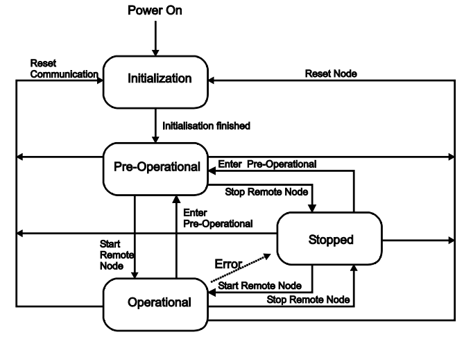
Init
When the fieldbus coupler is powered on again, it automatically transitions to the INITIALIZATION state. In that state, it tests the functionality of the module itself. A Process Image and Object Configuration are generated and if there are no errors during INITIALIZATION the Fieldbus Coupler changes to the PRE-OPERATIONAL state. If an error occurs the Fieldbus Coupler transitions to the STOPPED state.

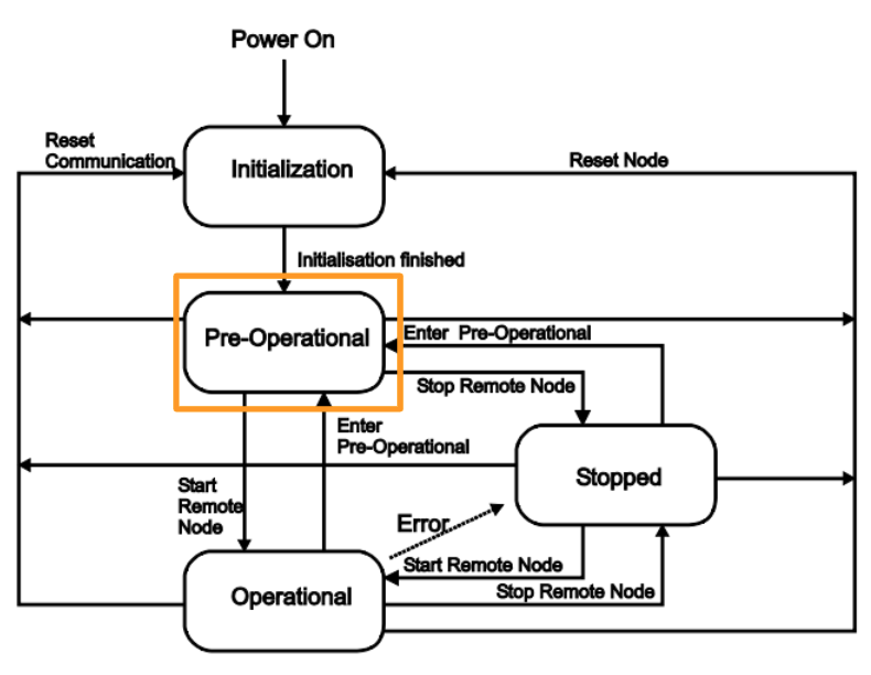
PRE_Operational
When the Fieldbus Coupler turned PRE-OPERATIONAL. You can get data from SDOs, but not PDOs. In that state, you can change the parameters, ID, etc. of the Coupler from Configuration Tools, and the new Configuration File will be saved in Flash Memory.
After receiving NMT Services Start_Remote_Node from Coupler, the Coupler will switch to OPERATIONAL state.
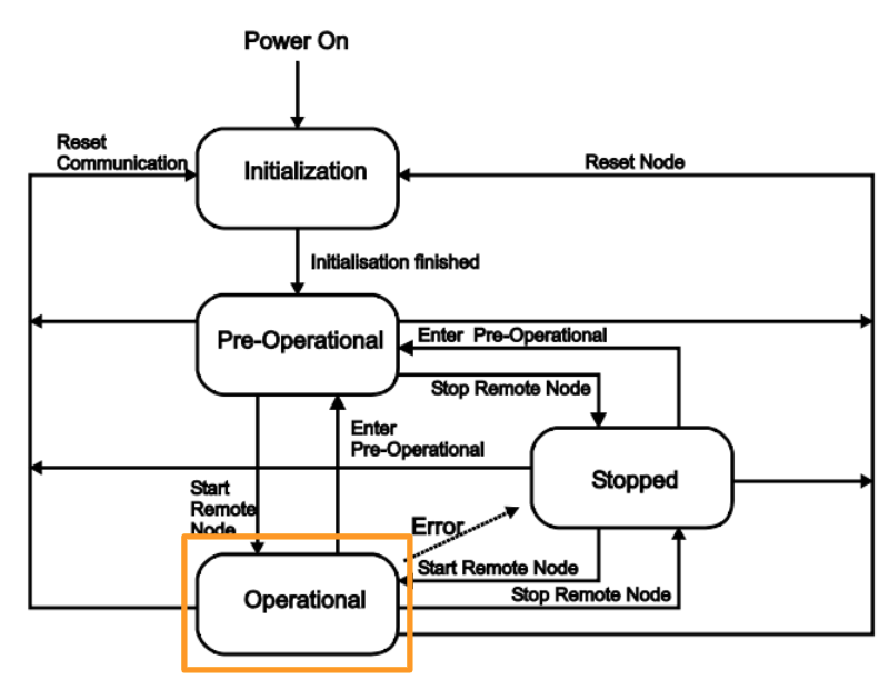
OPERATIONAL
Communication from SDOs and PDOs is possible in OPERATIONAL, but configuration cannot be changed (for example, COB-ID).
After receiving NMT Services Enter_Pre_Operional from Coupler,The status transition will change to PRE-OPERATIONAL again.
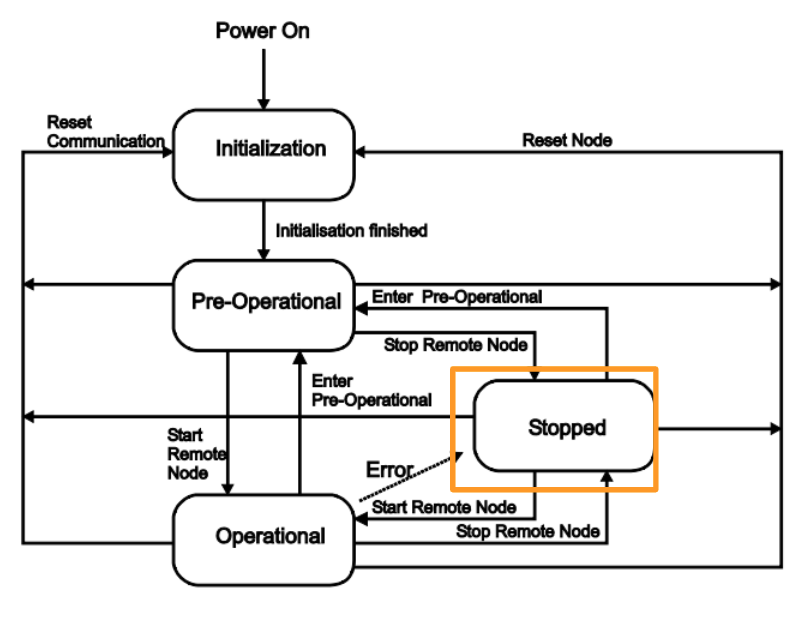
STOPPED
The STOPPED state now indicates that the module is FAULT. If the NMT service Stop_Remote_Node receives or an internal error occurs, it will be STOPPED. (e.g. if an I/O module is removed)
Modules in that state will not be able to communicate with SDOs or PDOs, only NMT services and Node-Grouarding/Heartbeat.
Network Management Objects
NMT Master uses multiple protocols to control the state of NMT Slave. The states are specified as follows:
- INITIALIZATION
- PRE-OPERATIONAL
- OPERATIONAL
- STOPPPED
It is also possible to change the state of all nodes at once or change the state of a specified node.
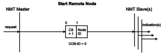
Start Remote Node
That Service switches the NMT Slave to Operational. If Node ID=0, change all Nodes to OPERATIONAL state.
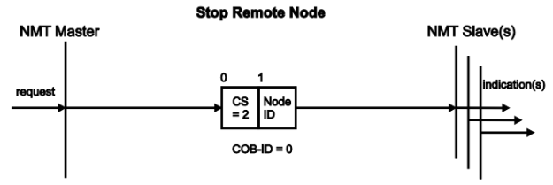
Stop Remote Node
This Service switches the NMT Slave to STOPPED state. If Node ID=0, change all Nodes to STOPPED state.
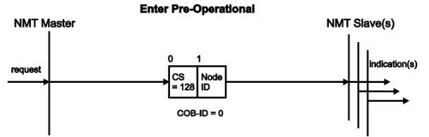
Enter Pre-Operational
This Service switches the NMT Slave to the PRE-OPERATIONAL state. If Node ID=0, change all Nodes to PRE-OPERATIONAL state.
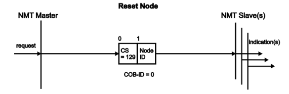
Reset Node
This Service resets the NMT Slave. If Node ID=0 then all Nodes Reset.
TM241CEC24U
CAN Interface
This is CANOPEN Terminal wiring of TM241CEC24U.

| Pin | Signal | Description |
| 1 | Not Used | Reserved |
| 2 | CAN_H | CAN_H Bus Line |
| 3 | CAN_SHLD | CAN shield(Optional) |
| 4 | CAN_L | CAN_L Bus Line |
| 5 | CAN_GUD | CAN Ground |
Transmission Rate
- 1000 kbit/s for bus length of 20 m for CANopen
- 800 kbit/s for bus length of 40 m for CANopen
- 500 kbit/s for bus length of 100 m for CANopen
- 250 kbit/s for bus length of 250 m for CANopen
- 125 kbit/s for bus length of 500 m for CANopen
- 50 kbit/s for bus length of 1000 m for CANopen
- 20 kbit/s for bus length of 2500 m for CANopen
Implementation
Download EDS File
Please Download the EDS File from Wago Home Page
https://www.wago.com/global/i-o-systems/fieldbus-coupler-canopen/p/750-347#downloads
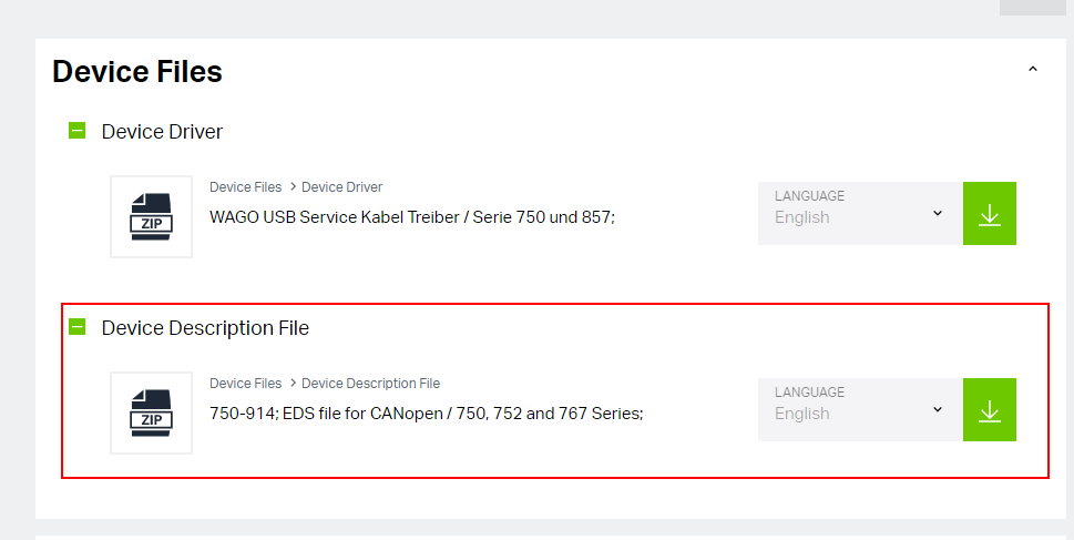
A zip file is downloaded.

You can find all files that are necessary for configuring a CAN OPEN Network with Wago 750-347.
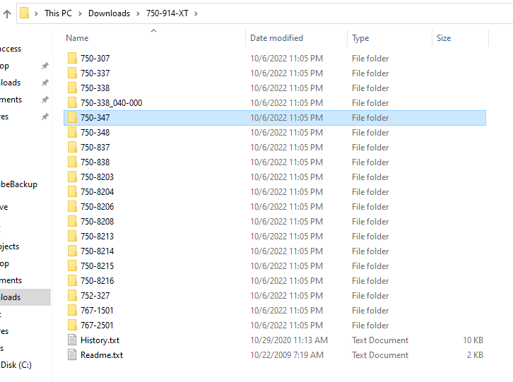
Configuration
Select the

Install 750-347 CANOPEN Coupler
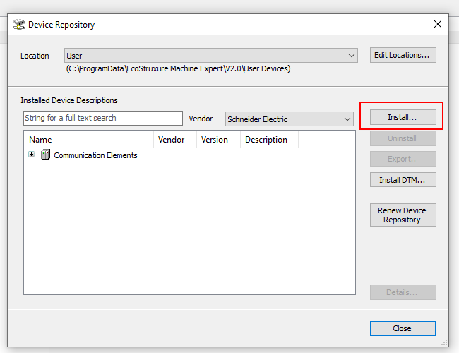
Let’s import the EDS file from EcoStruxure Machine Expert. Go to Tools>Device Repository.
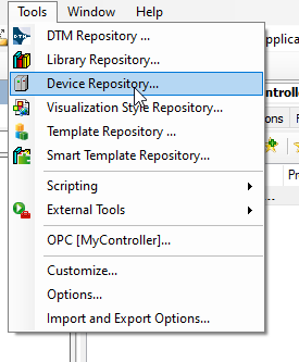
Click the Install button.
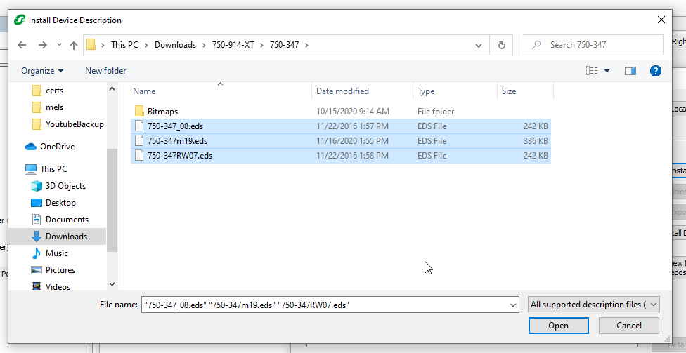
Select the EDS Files that we download from Wago Web Site.
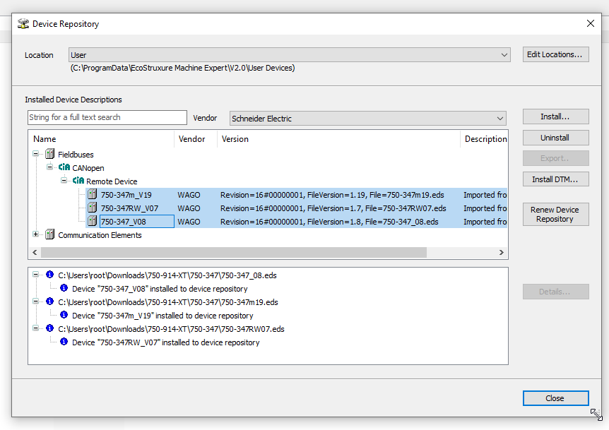
Done!
Add CanOPEN Master
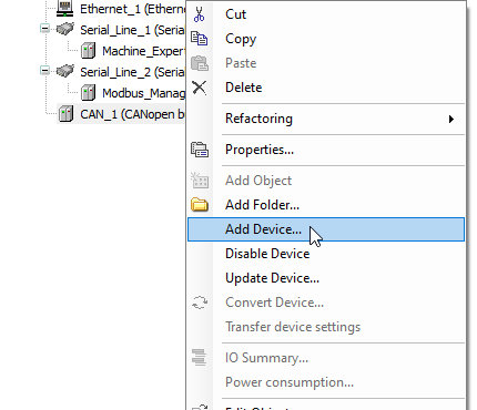
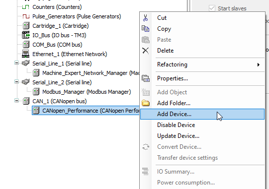
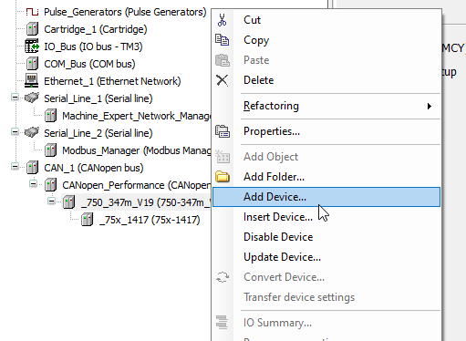
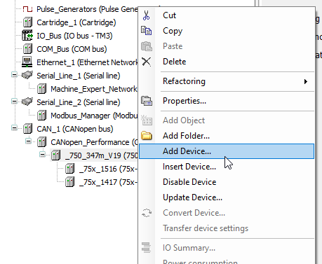
Clcik click the CAN_1(Canopen…)>Add Device.
Go to CANOpen>CANopenManager>CANopen Performance>Add Devices to add a CANOPEN Master.

CANOpen Master is inserted into your network.

Add 750-347
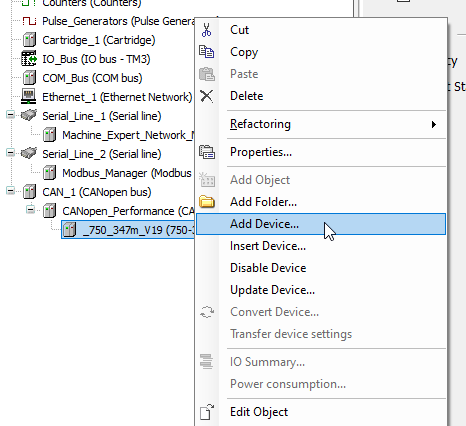
Now we can insert the Wago 750-347 CANOpen Coupler. Go to CANOpen_Performance>Right Click >Add Device.
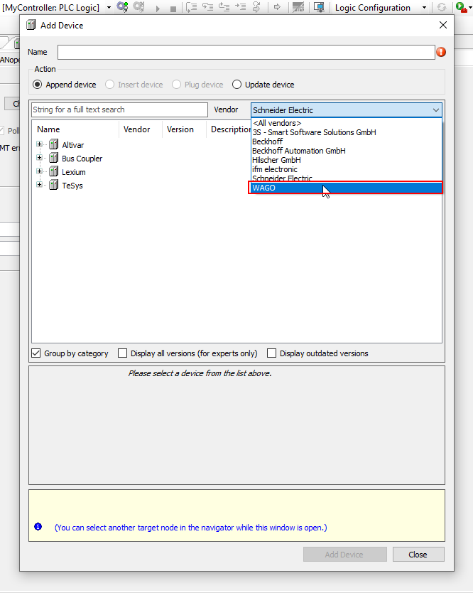
Select Wago in the Vendor Field.
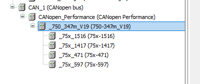
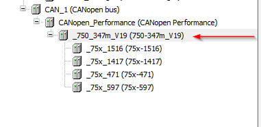
Choose 750-347m_V19>Add Device.
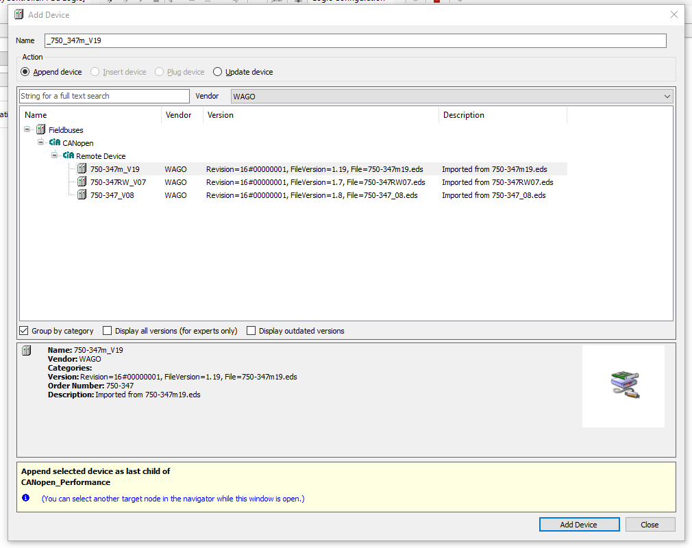
750-347 CANOPEN Coupler is inserted.

Add 750-1417
We can insert 750-1417 8 channel Digital Input into Slot1.
Right Click>Add Device.
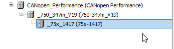
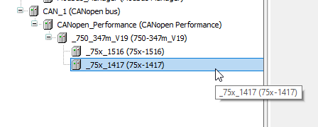
Search 1417 and choose 75x-1417>Add Device.
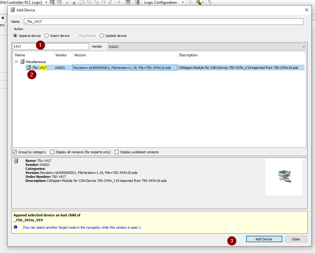
750-1417 8 channel Digital input is inserted in Slot1.
Add 750-1516
Insert 750-1516 8 channel Digital Output into Slot2.
Right Click>Add Device.
Search 1516 and choose 75x-1516>Add Device.

Slot2が750-1516 8チャンネル デジタル出力、追加されました。
Add 750-471
Insert 750-471 4 channel Analog Input into Slot3.
Right Click>Add Device.
471を検索し>75x-471を選択>Add Deviceします。
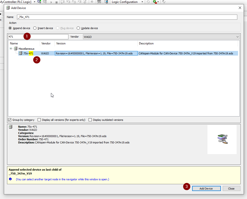
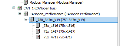
Slot3が750-471 4チャンネル アナログ入力、追加されました。
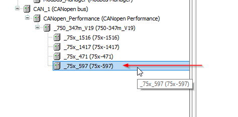
Add 750-597
Insert 750-471 8 channel Analog Output into Slot4.
Right Click>Add Device.

Search for 597 and select >75x-597>Add Device.
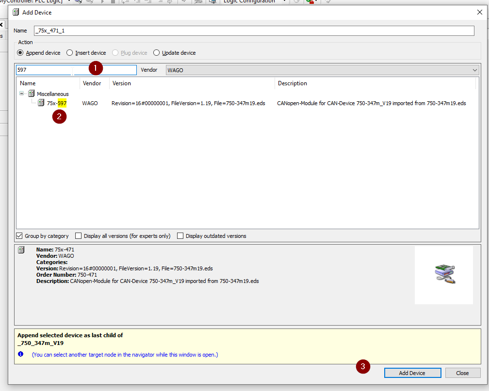
Slot 4 is now installed with 750-597 8-channel analog output.
Configure 750-347
The next step is to set up the 750-347 CANOPEN Coupler.
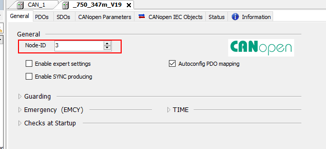
Node ID
Set the Node-ID in the General Tab. The ID of this CANOPEN Coupler is 3.
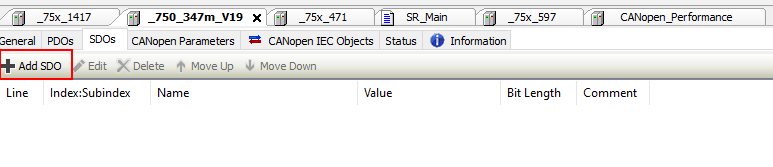
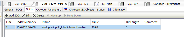
Enable Analog
Next, write True to Enable Analog, open the SDOs Tab and click >Add SDO.
Choose 16#6423:16#00 and Ok.

Index16#6423: SDO for SubIndex16#00 has been added.
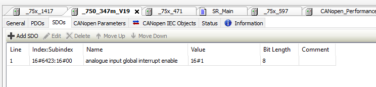
Click on the Field of Value.
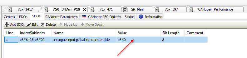
Just change the value to 16#1.
Program
Now we can start to create the program.
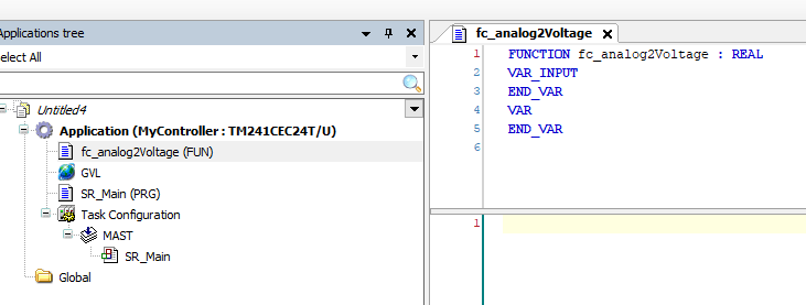
fc_analog2Voltage
First, create a function that converts the input value of the analog input module to voltage.
Go to Application>Add Object>POU.

Enter a name for your Function > set Return Type to Real > Add.

Function is inserted.
Add a simple program inside.
| FUNCTION fc_analog2Voltage : REALVAR_INPUT iValue :WORD;END_VARVAREND_VAR VAR CONSTANT cMaxRawValue :REAL:=32767.0; cMaxScaling :REAL:=10.0; cMinScaling :REAL:=0.0;END_VAR fc_analog2Voltage:= (TO_REAL(iValue)/cMaxRawValue) *cMaxScaling; |
fc_Setpoint2Analog
Next, add a Function that converts Setpoint to an analog output module value.

Enter a name for the Function>Return Type is set to Real>Add.

Add a simple program inside.
| FUNCTION fc_Setpoint2Analog : WORD VAR_INPUT iSetPoint :REAL; END_VAR VAR cMaxRawValue :REAL:=32767.0; cMaxScaling :REAL:=10.0; END_VAR IF iSetPoint >=0.0 AND iSetPoint <=cMaxScaling THEN fc_Setpoint2Analog:= TO_WORD( (iSetPoint/cMaxScaling)*cMaxRawValue); ELSE fc_Setpoint2Analog:=0; END_IF |
GVL_750_354
The next step is to create a Global Variable List.

Enter the GVL name and Add it into your project.
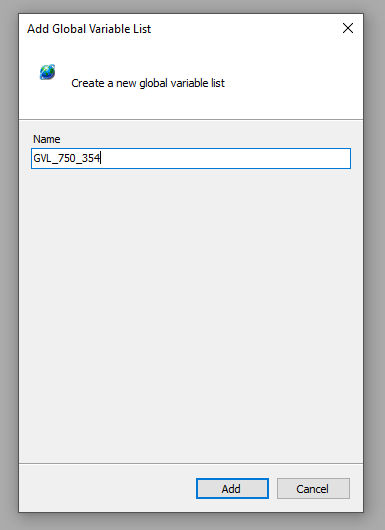
GVL is inserted in your project.

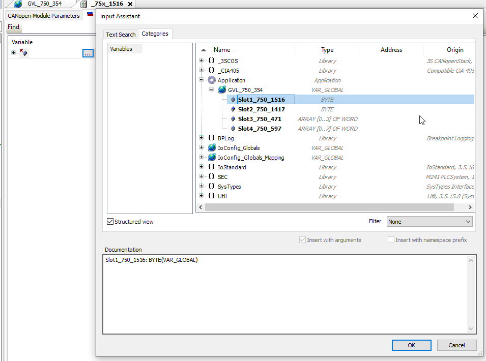
Add variables tied to each Slot in the GVL.

Link Variable to 750-1516
Link the GVL variable to Slot1 750-1516.

Click on Variable’s … button, select GVL Slot1_750_1516 >Ok.

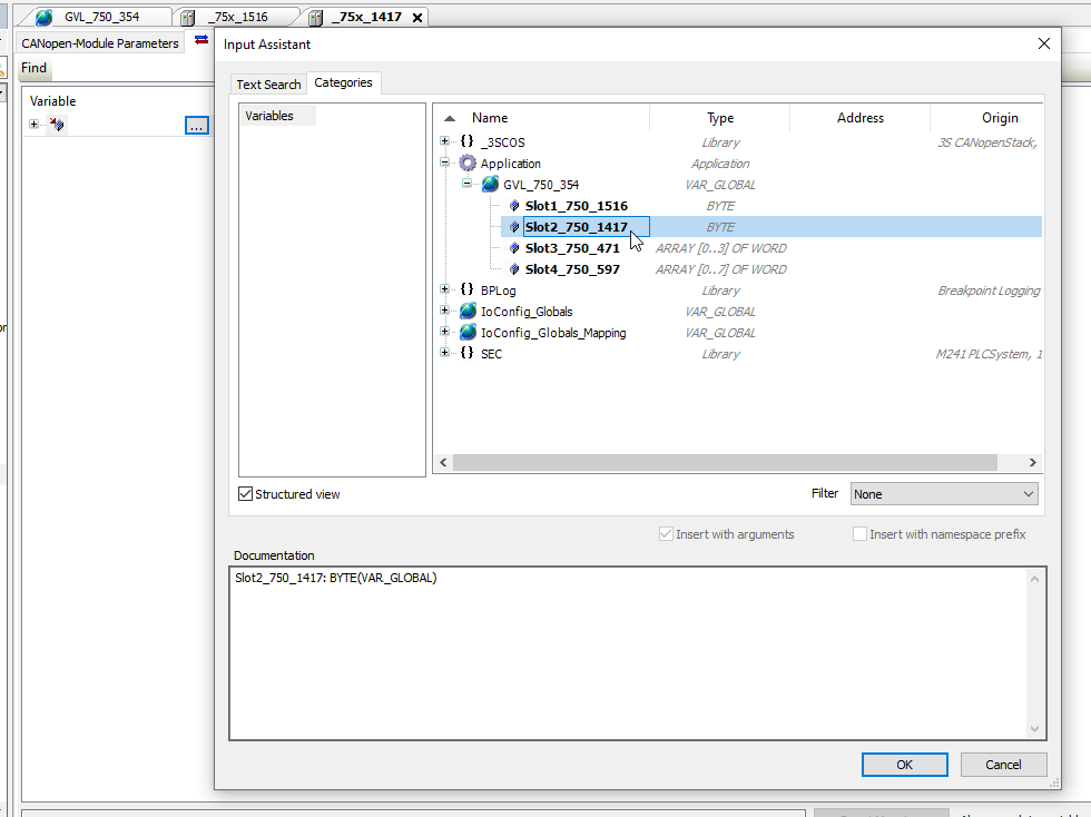
Link Variable to 750-1417
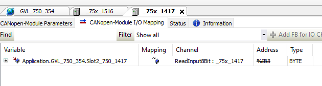
Link the GVL variable to Slot2 750-1417.

Click on Variable’s … button, select GVL Slot2_750_1417 >Ok.
Done.
Link Variable to 750-471
Tie the GVL variable to Slot3 750-471.

Click on Variable’s … button, select GVL Slot3_750_471 >Ok.

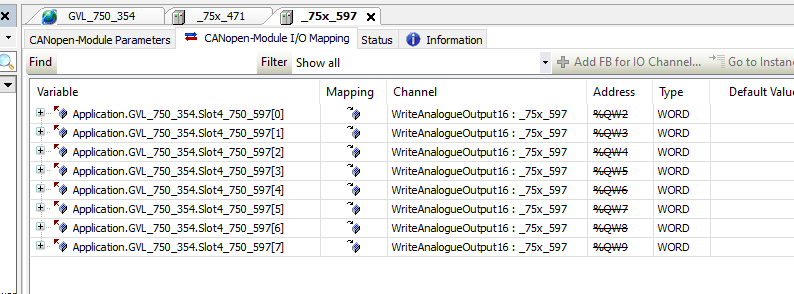
Link Variable to 750-597
Link the GVL variable to Slot4 750-597.
Click on Variable’s … button, select GVL Slot4_750_597 >Ok.
MAIN
Finally, we just turn ON/OFF the output of the coupler alternately, and then just check the analog input/output data!
| PROGRAM SR_Main VAR Channel1_Value:REAL; Setpoint1:REAL; myTon:TON; istep:INT; END_VAR Channel1_Value:=fc_analog2Voltage(iValue:=GVL_750_354.Slot3_750_471[0]); GVL_750_354.Slot4_750_597[4]:=fc_Setpoint2Analog(iSetPoint:=Setpoint1); CASE istep OF 0: myTon(IN:=TRUE ,pt:=T#0.1S ); GVL_750_354.Slot1_750_1516:=16#0F; IF myTon.Q THEN GVL_750_354.Slot1_750_1516:=0; myTon(IN:=FALSE); istep:=10; END_IF 10: myTon(IN:=TRUE ,pt:=T#0.1S ); GVL_750_354.Slot1_750_1516:=16#F0; IF myTon.Q THEN GVL_750_354.Slot1_750_1516:=0; myTon(IN:=FALSE); istep:=0; END_IF END_CASE |
Result
LED Status
without Connection
From startup to normal
In Normal
Program
