This is the fifth episode of the Tutorial on B&R Automation Studio. This time we have a rare opportunity to touch a real machine, so we will briefly explain how to build a simple Project from the Hardware Configuration in B&R’s Automation Studio.
Let’s get started!
Reference Link
http://soup01.com/en/category/br_en/
Implementation
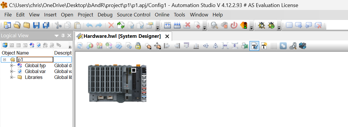
Let ‘s start by building the Hardware Configuration.
Configuration
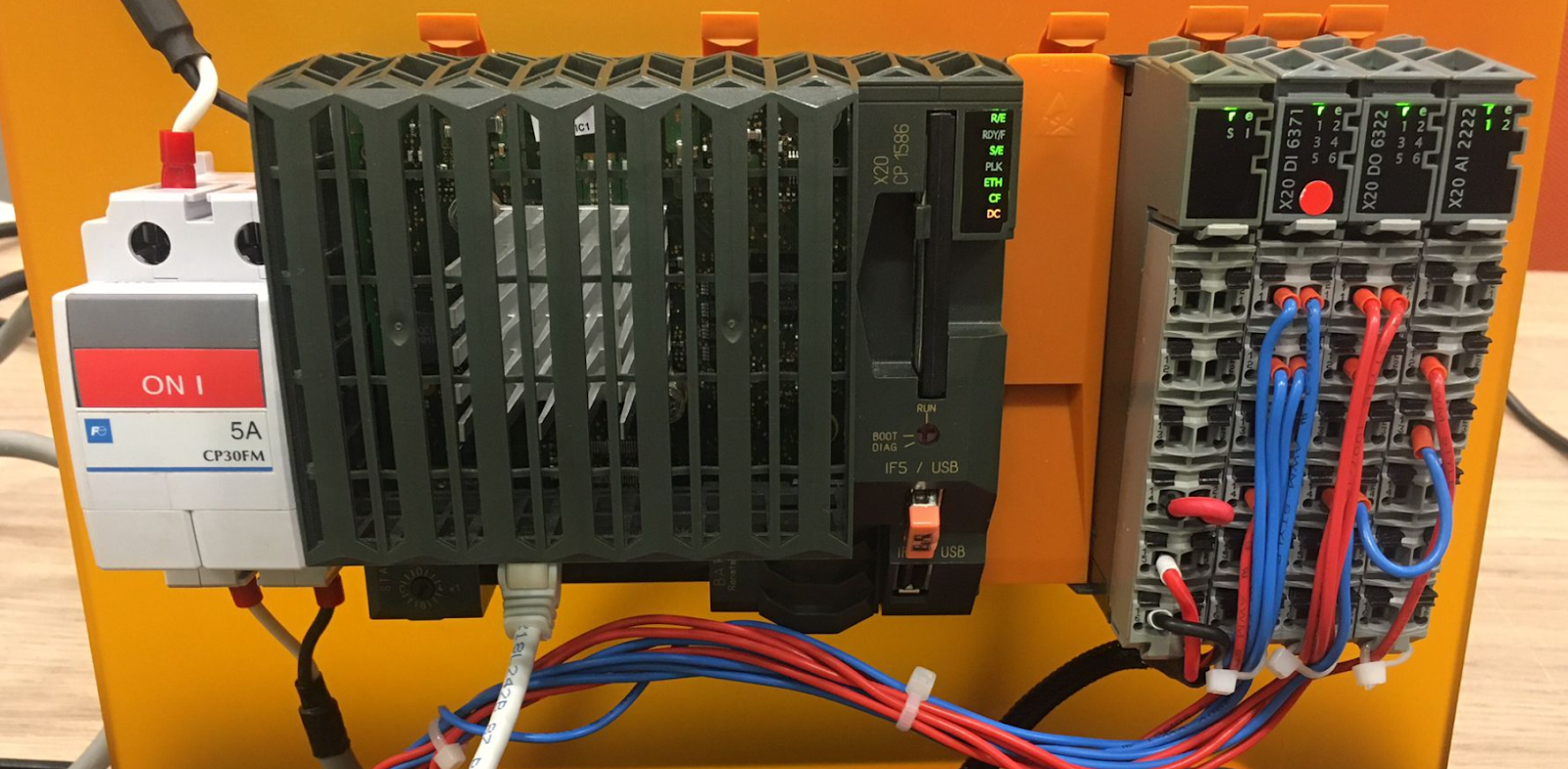
In this case, the X20CP1586 actual device is used, so when creating a new project, enter CP1586 in the Filter field and select X20CP1586.
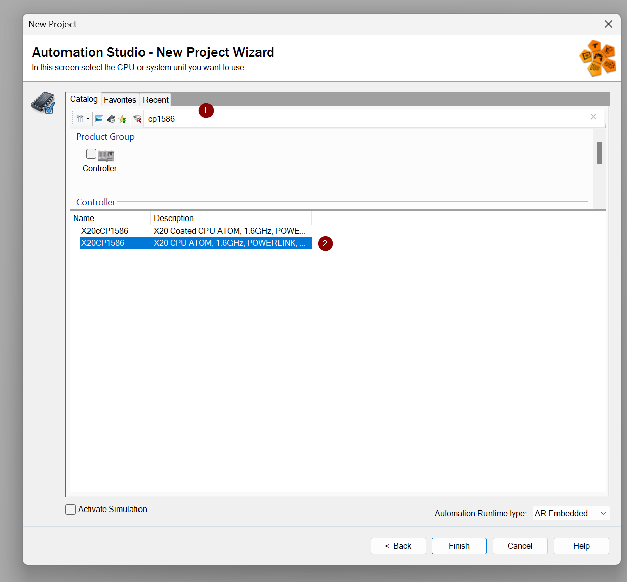
Done!The hardware used for the new project is now X20CP1586.
Add Slot X20DI6371
Three Slots will be installed on the actual machine this time, and the project will specify the settings according to the configuration of the actual machine.

In Slot 1, the X20DI6371 digital input, so search for 6371 in the Toolbox and add the X20DI6371 next to the CPU.
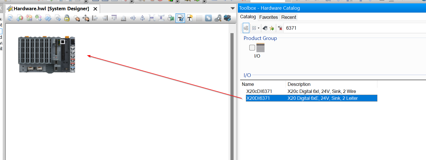
If the relevant module can be added, a green ICON with + is displayed next to the Slot.
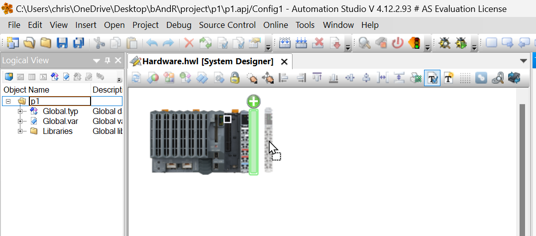
The operation is shown in the diagram below.
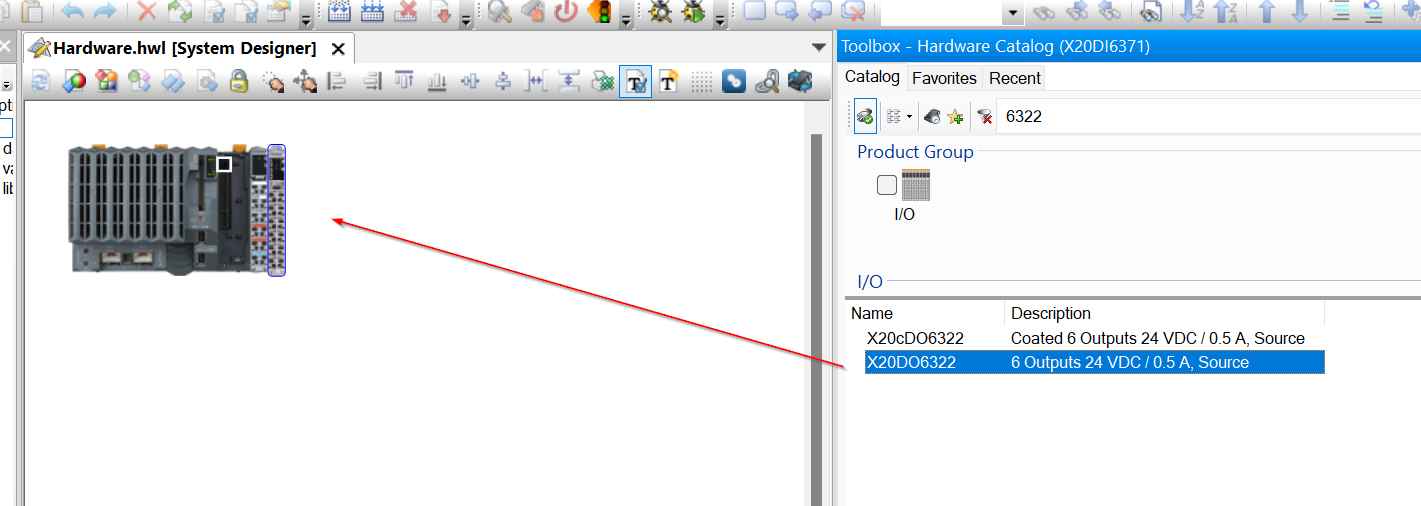
Add Slot2 X20DO6322
The X20DO6322 digital output is installed in Slot 2.
Search for 6322 in the Toolbox and add X20DO6322.
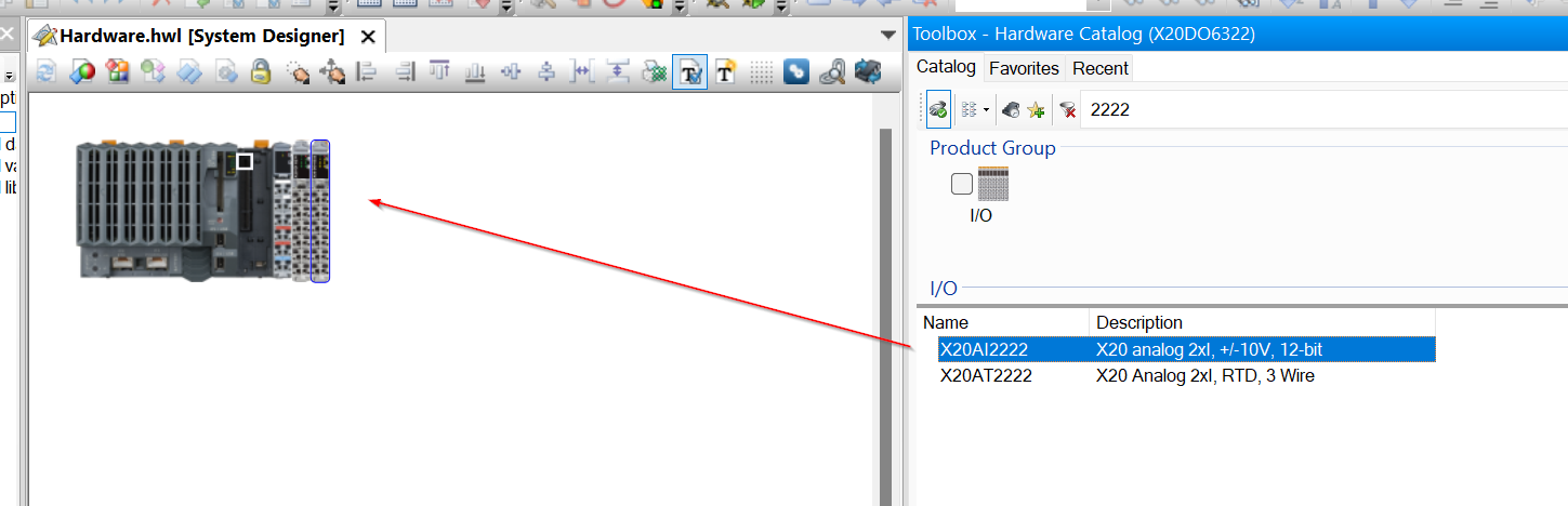
Add Slot3 X20AI2222
The X20AI2222 analogue input is installed in Slot 3.

Search for 2222 in the Toolbox and add X20AI2222 in the next slot.
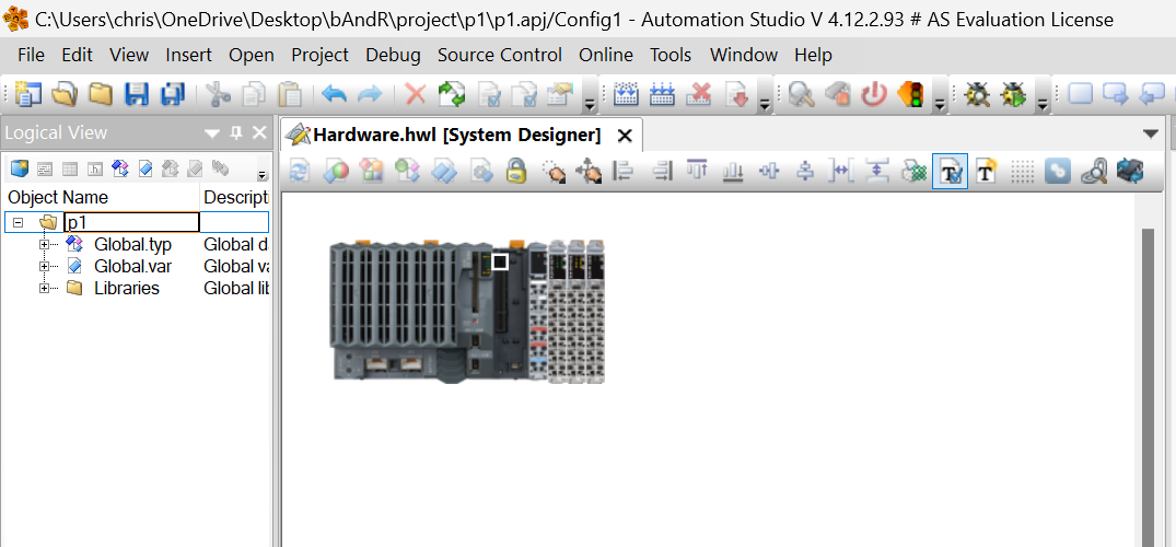
Result
Done!
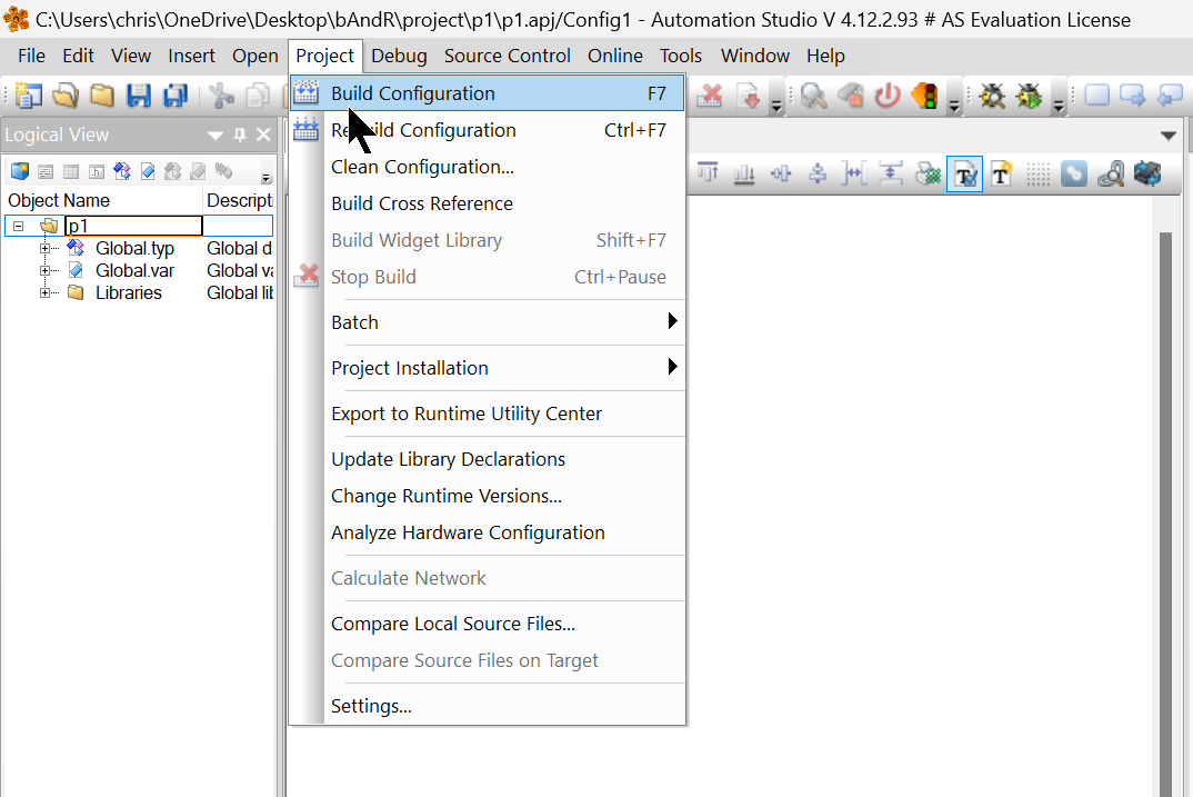
Build
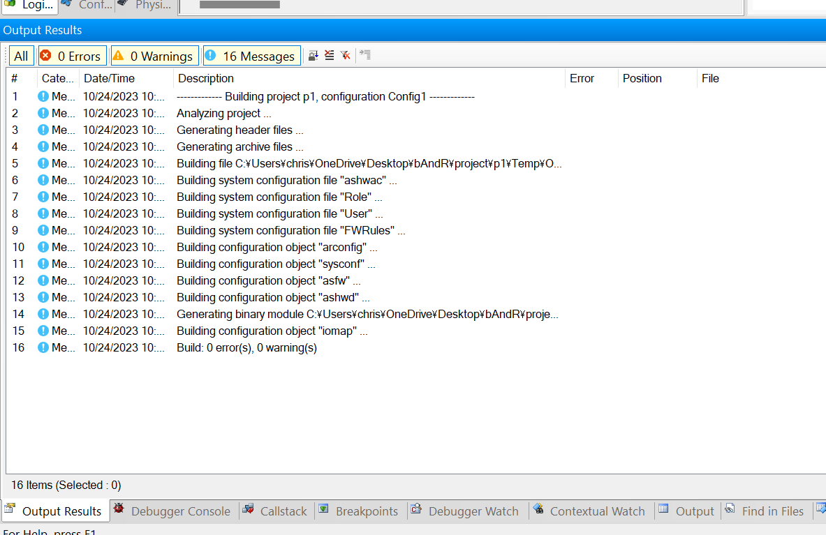
Compile your project once in Project>Build Configuration.
Recheck that there are no errors in the Output Result.
IP Setting
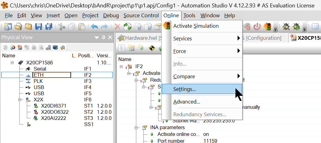
Now click X20CP1586>ETH>Configuration to set the IP of the CPU.
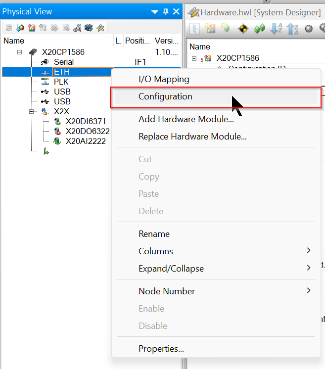
Settings relating to the CPU’s Ethernet Port are displayed.
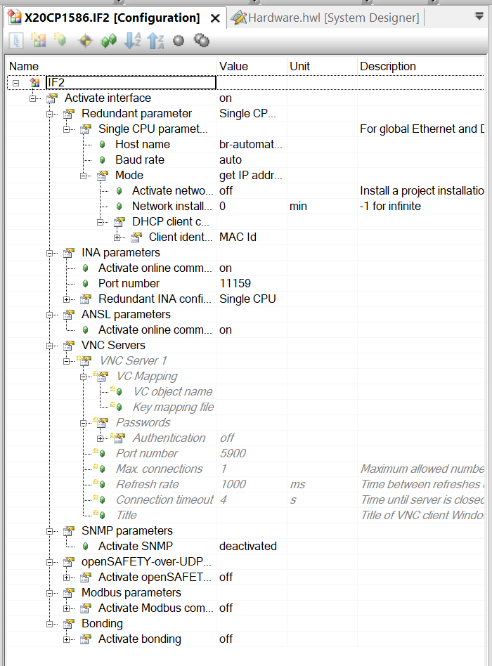
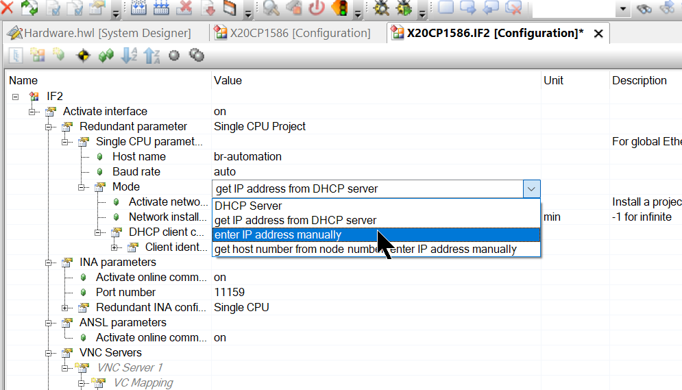
Open Activate Interface>Redundant parameter>Single CPU parameters.
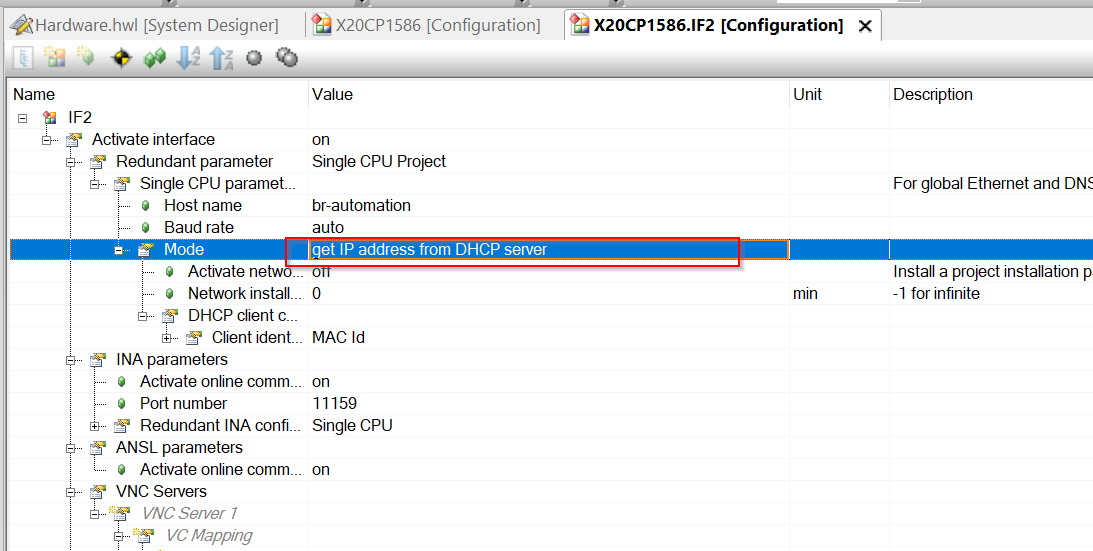
Select the Mode value with “Enter IP Address manually”.
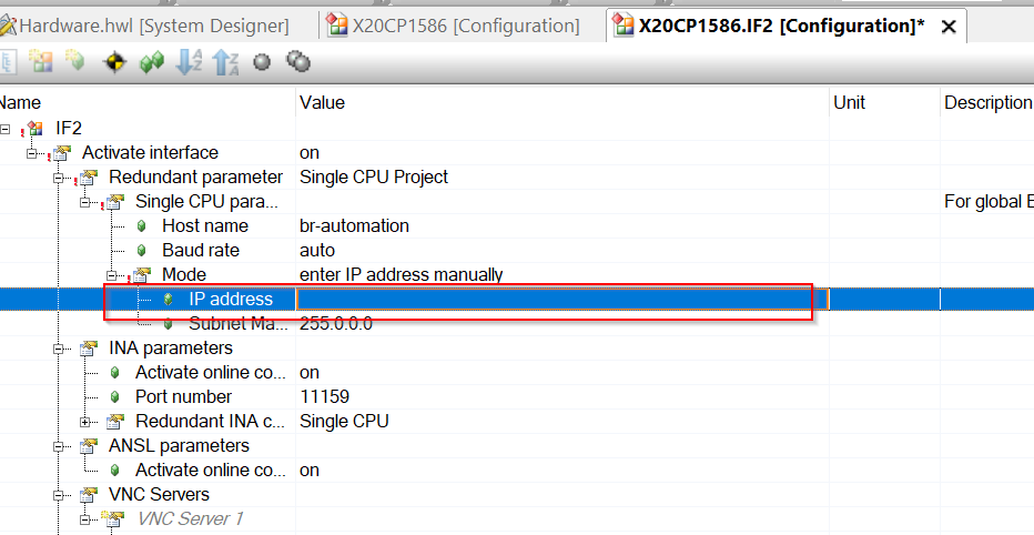
Static IP can now be configured and IP address and Subnet Mask can be entered.
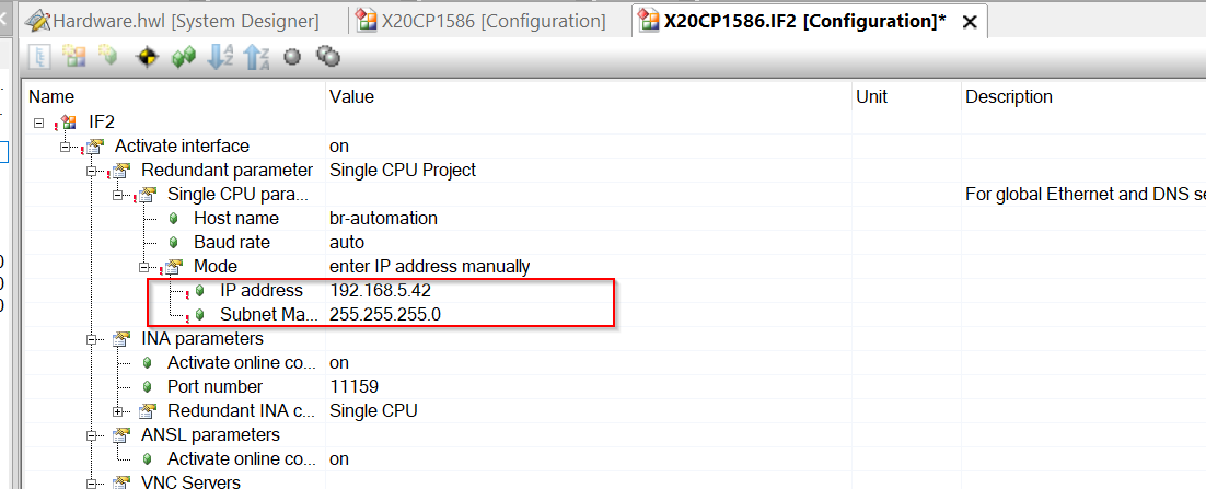
Configure the IP and Subnet according to the actual application.
Offline Installation
In fact, there are several ways to transfer a project to a B&R CPU, and we would first like to introduce “Offline Installation”, which does not require a direct connection to the CPU.
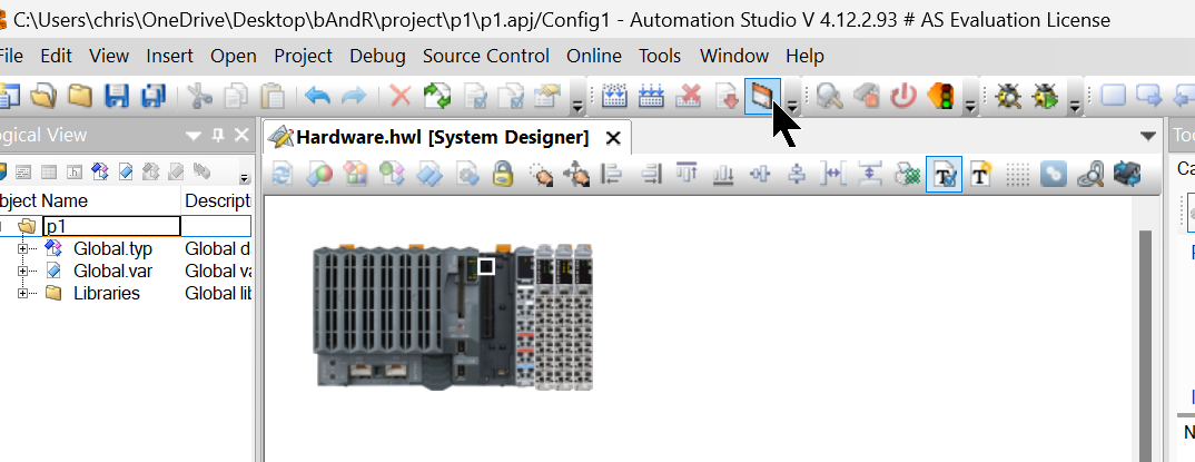
Display Offline installation from the Toolbar in Automaton Studio.
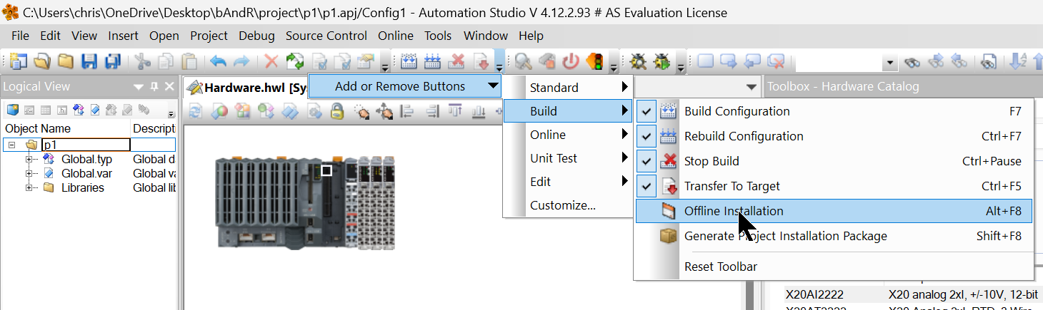
A small Window icon appears, as shown below, and click on it.
The SD CARD Slot position may change depending on the CPU, but the SD CARD Slot of the X20CP1586 used in this project is shown in the diagram below.
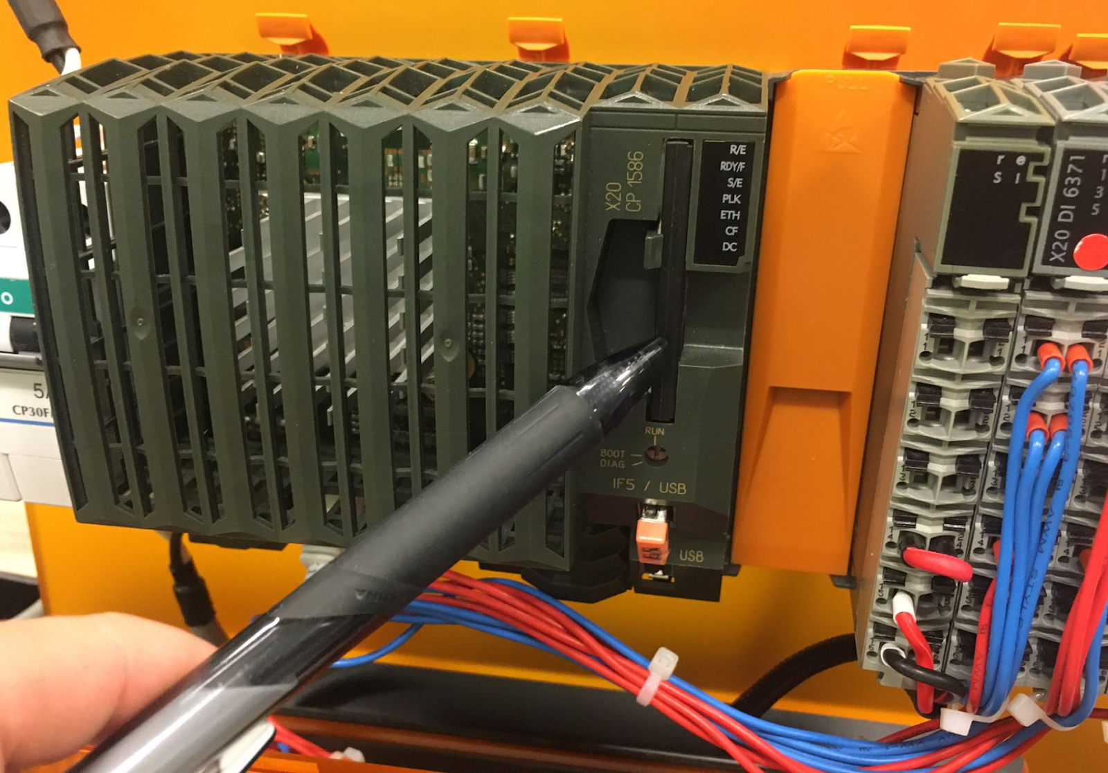
Make sure to switch off the CPU, unplug the SD CARD and connect it to the CARD Reader.
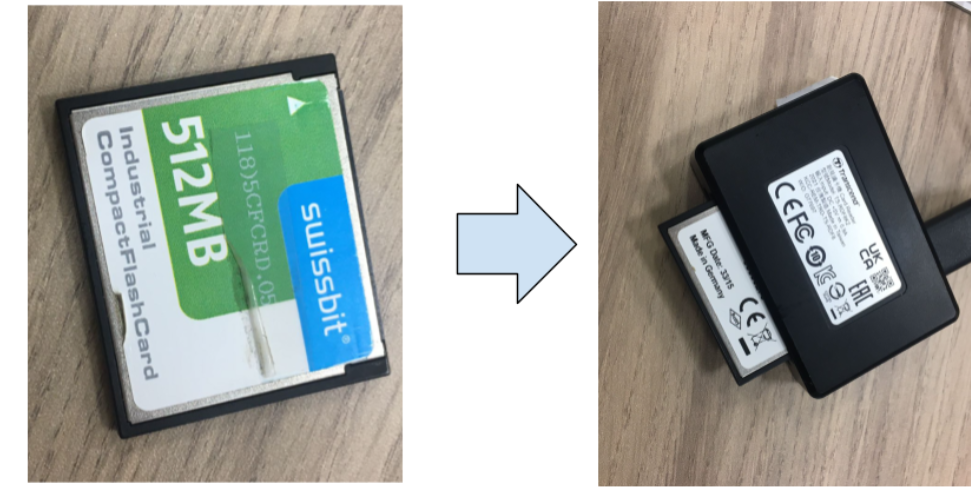
The SD CARD insertion and removal operation can be seen in the video below.
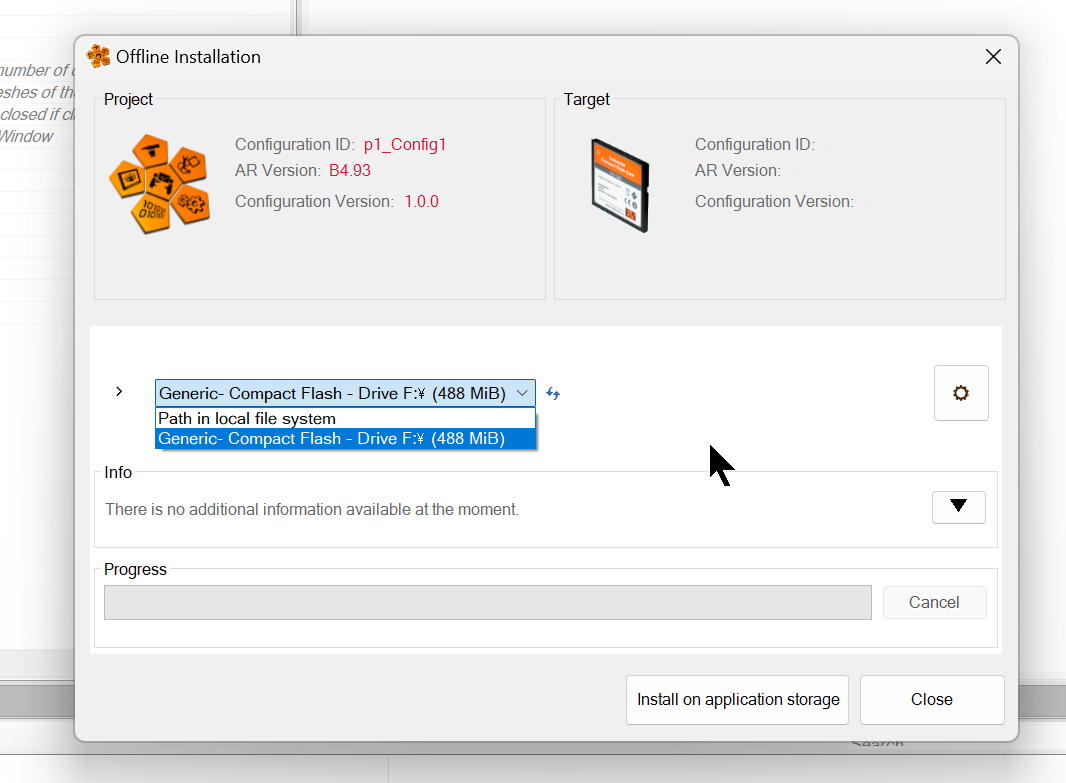
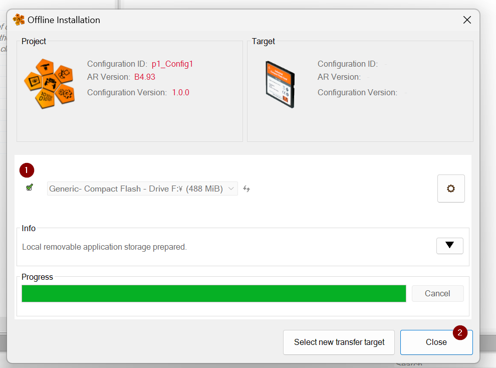
The Offline Installation screen appears.
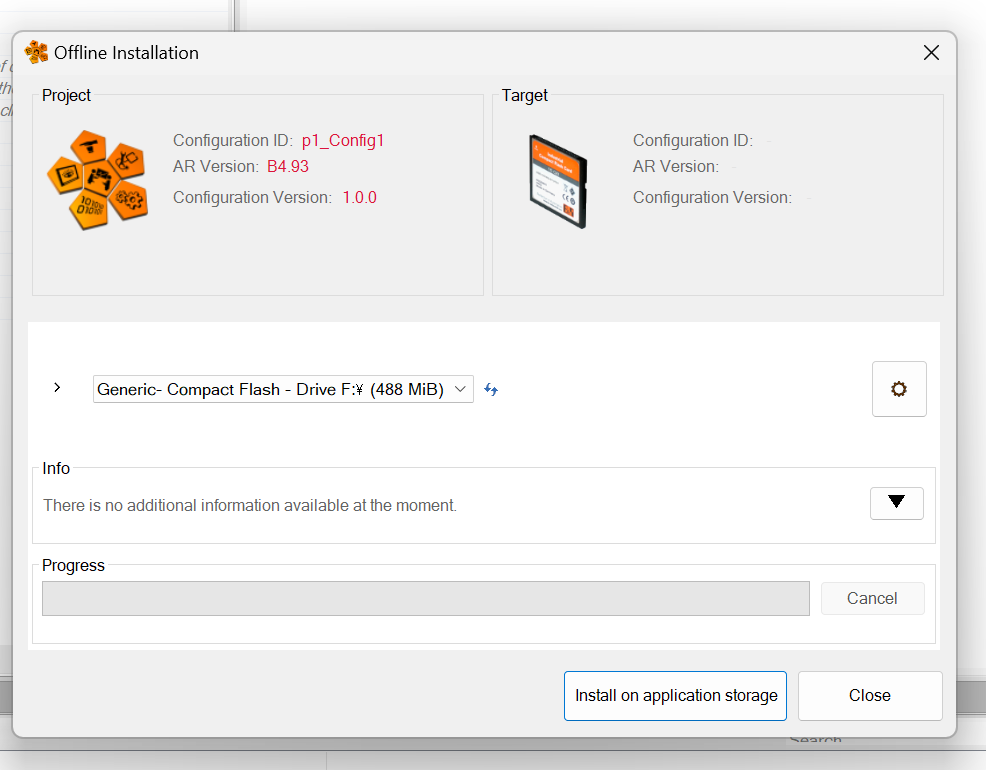
Set the correct Path to write the project.
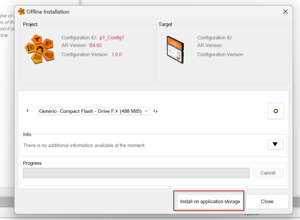
Click on the “Install on application storge” button to burn the project to the SD Card.
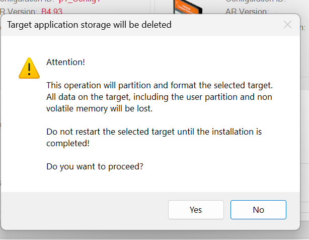
This operation will erase all data in the SD Card, are you sure? Proceed with Yes.
Just a second..
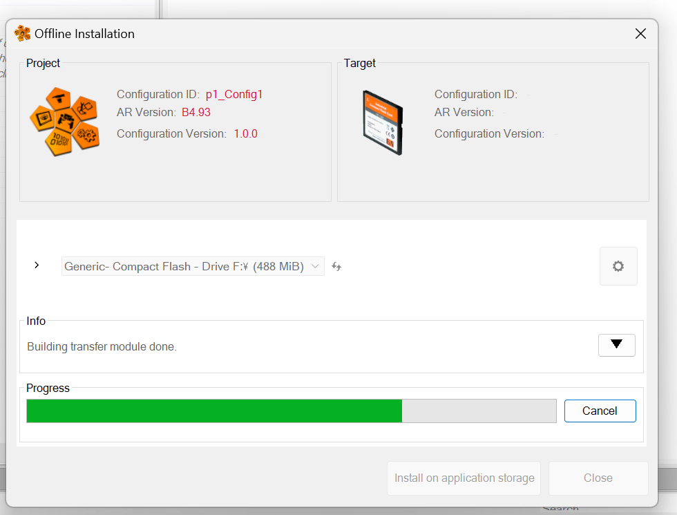
When the project has finished writing to the SD CARD, a small green mark appears on the screen and click Close.
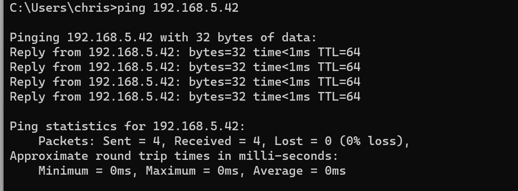
After I inserted the SD CARD into the CPU, switched the power back on and pinged from the command, the IP address I had just set for the project was also replied to.Done!
Connect Online
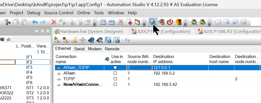
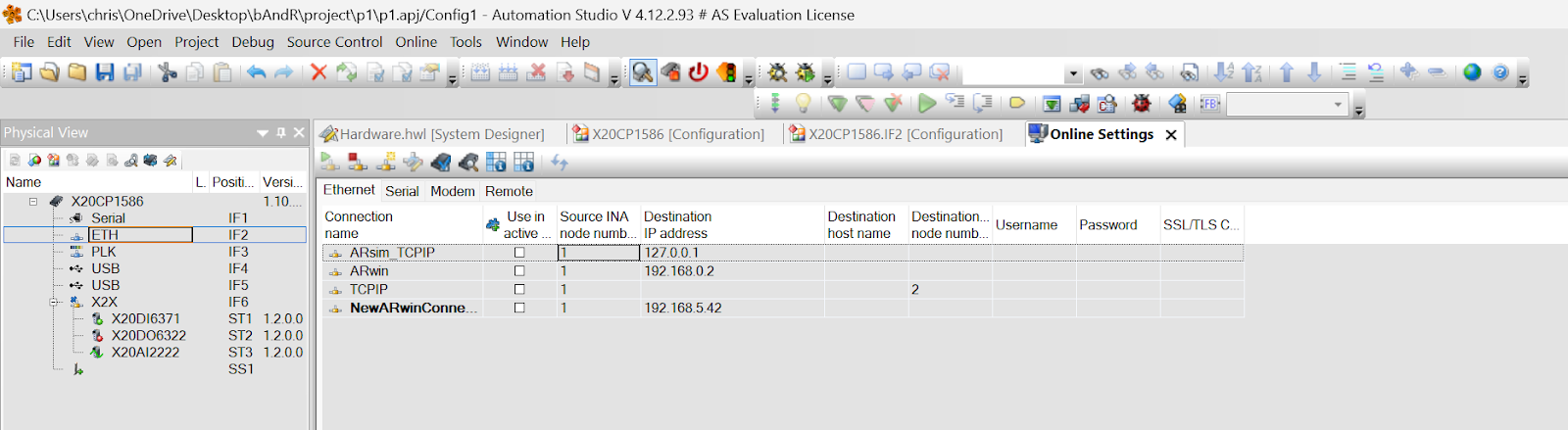
Next, open Online>Settings to connect Automation Studio to the CPU.
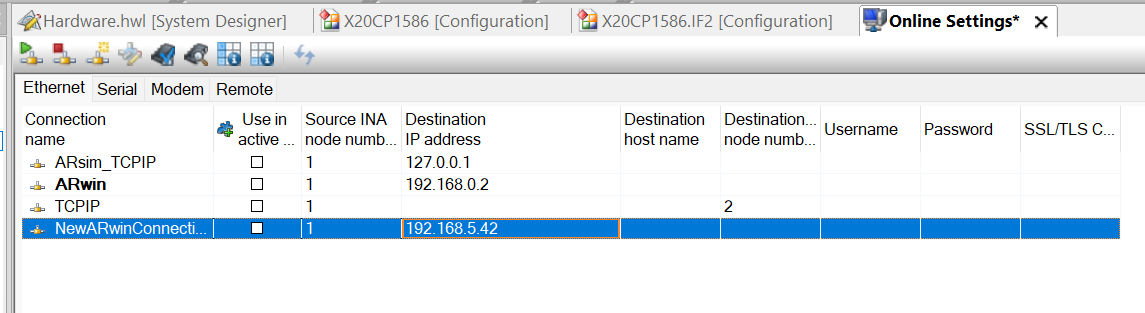
Right-click on the screen>Add ARwin Connection to add a new connection.
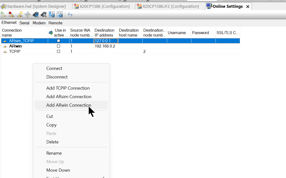
Destination is the IP address of the CPU.
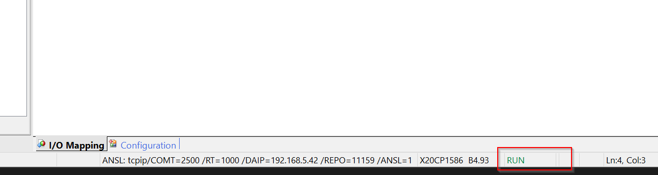
Click on the green Online button.
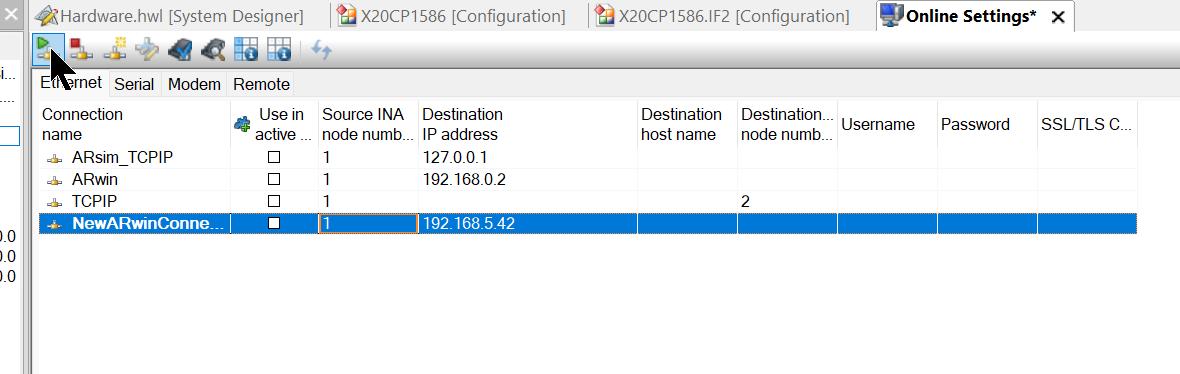
Done!The Automation Studio is now connected to the CPU and “RUN” is also displayed in the lower right-hand corner of the Automation Studio.
Monitor
Let’s try to Monitor the CPU.
Done!
Force
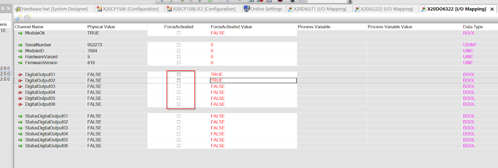
The current status of the modules you have just added can be checked directly from the I/O Mapping screen.
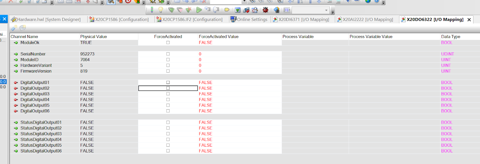
If you want to force output, first set the value you want to force to the ForceActivated Value field.
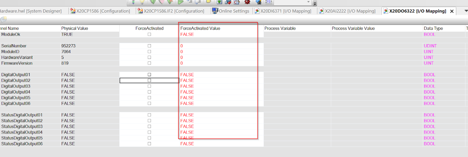
The following example forces DigitalOutput01 and DigitalOutpu02 to TRUE.
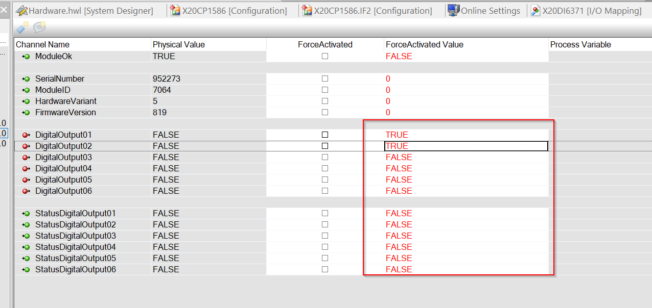
The next step is to put a Check in the ForceActivated field.
Result
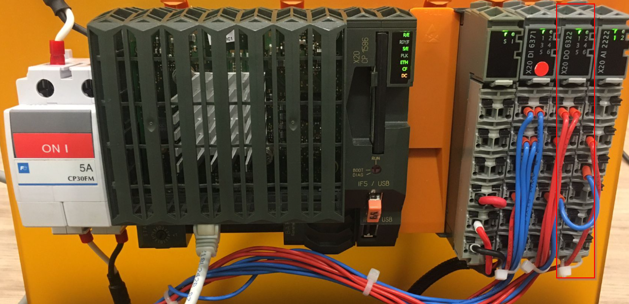
The diagram below shows the actual state of the X20DI6371 input module.

This is a forced output operation.
Implementation‐2
Once Hardware Configuration has been completed, it is now time to Mapping the module’s signals with the User Program.
Mapping
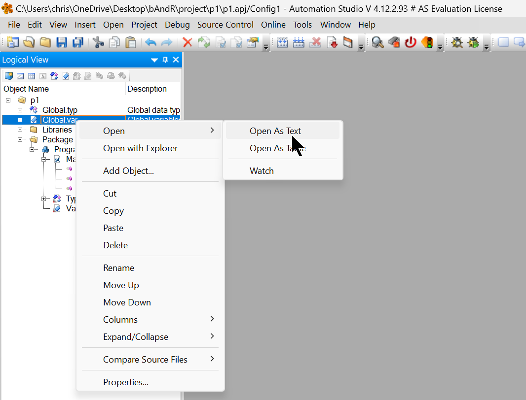
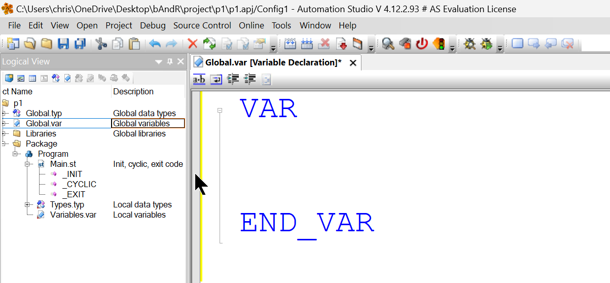
Open Project Name>Global.var>right-click>Open>Open As Text.
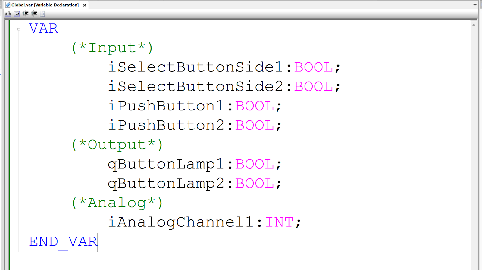
Add variable declaration statement for VAR END_VAR.
Define the variables used in this article.
Assign
Now that the Global variables have been defined, the next step is to link the module’s IO signals to those variables.
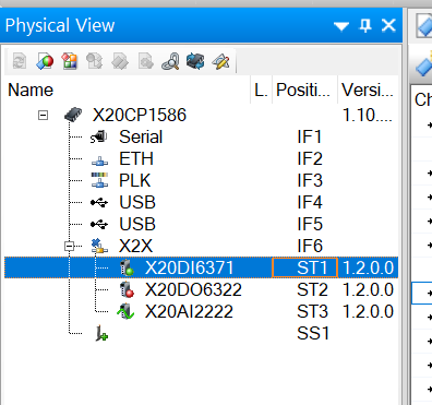
Double-click Physical View>X20CP1586>X2X>X20DI6371.
Click on Process Value and a small … button appears in the column.
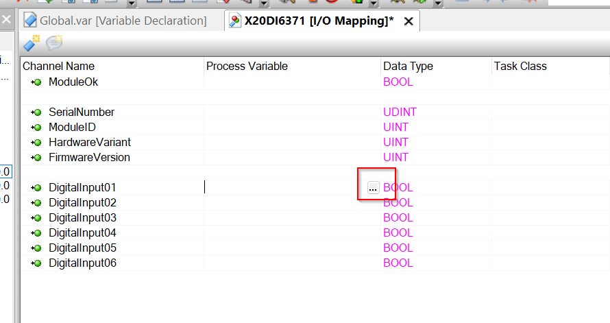
Click on this button and link it to the Global variable you have just defined.
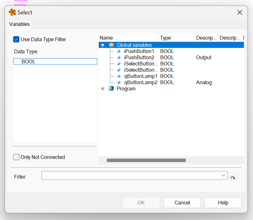
Done!
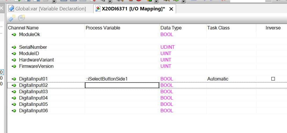
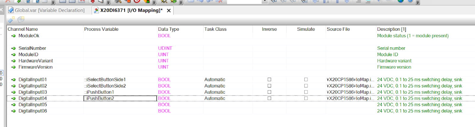
X20DI6731
This is the X20DI6731 Mapping.
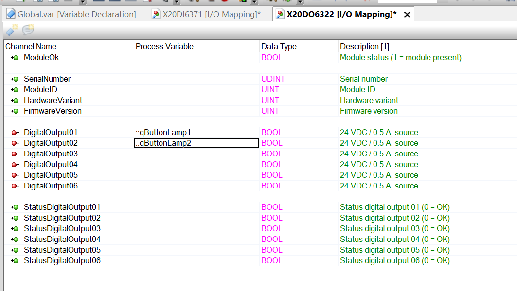
X20DO6322
This is the X20DO6322 Mapping.
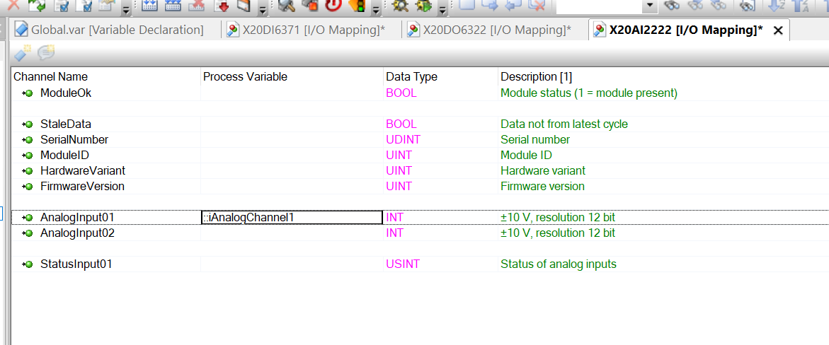
X20AI2222
This is the X20AI2222 Mapping.
Program
This is the program, which outputs a ramp wired to X20DO6322, depending on the state of the Select switch and Push Button wired to X20DI6371.
It also scales the analogue input wired to X20AI2222 to 0-10v.
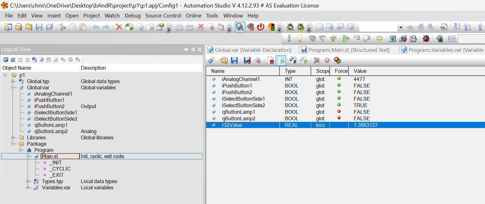
| PROGRAM _INIT (* Insert code here *) END_PROGRAM PROGRAM _CYCLIC (* Insert code here *) qButtonLamp1:=iPushButton1 AND iSelectButtonSide1; qButtonLamp2:=iPushButton2 AND iSelectButtonSide2; r32Value:= (INT_TO_REAL(iAnalogChannel1)/32767)*10.0; END_PROGRAM PROGRAM _EXIT (* Insert code here *) END_PROGRAM |
Result
IO data for each Slot can now also be obtained, as shown in the diagram below.