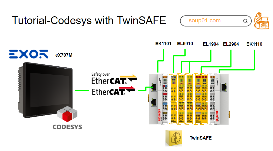
This article uses Codesys and the CODESYS SAFETY FOR ETHERCAT SAFETY MODULE to build the Safety logic for Beckchoff’s EL6910 from Codesys.
Let’s get started!
Reference Video
Codesys.Let’s use EL6910 TwinSAFE!
Beckhoff.Let’s play with TwinSAFE_Part1.EN
Reference Link
CODESYS extension for EtherCAT?
CODESYS extension for EtherCAT based safety solutions with Beckhoff TwinSAFE logic modules EL6900, EL6910 and EK1960 with CODESYS EtherCAT master stack. CODESYS controller with the CODESYS EtherCAT master stack. It thereby provides users and control manufacturers who do not want to develop their own SIL3 safety controller with a flexible and economical solution for the safe automation of machines and plants.
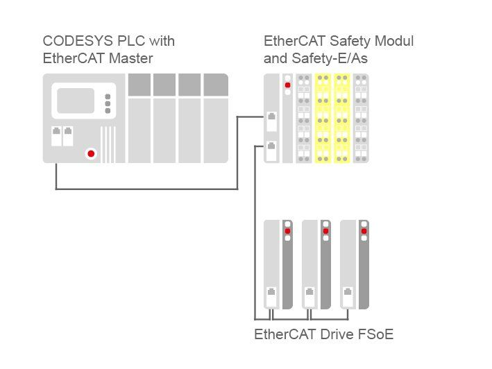
Safety I/O and safety modules operate on the EtherCAT fieldbus together with standard I/O and drives; CODESYS Safety for EtherCAT safety modules extend CODESYS and include all functions required for developing functional safety applications:
- TÜV-certified products allow CODESYS projects with EtherCAT controllers to be extended with CODESYS.
- EtherCAT master stack for the development of safety functions with TÜV-certified safety logic modules, digital FSoE I/O modules and analogue TSC input modules on the Beckhoff EtherCAT network.
- Extensions with safety-specific editors and configurators are seamlessly integrated into the CODESYS development system and the CODESYS EtherCAT configurator.
- System integration and adaptation costs are reduced, acceptance costs are lower and simple safety applications can be realized cost-effectively and scalably.
- Safety levels up to PL-e according to DIN EN ISO 13849
- Up to SIL3 according to IEC 62061/61508 (depending on input/output devices and programmed logic)
- Limited variable programming (LVL) according to ISO 13849 and IEC 62061
- Beckhoff logic modules EL6900 or EL6910 as EtherCAT Camp (TwinSAFE-Logic) and EK1960 as EtherCAT Coupler (TwinSAFE-Compact Controller).
- Digital SIL3 I/O modules: FSoE modules (Failsafe over EtherCAT) are installed and used in the Codesys IDE from the respective ESI File.
- Analogue SIL2 input module
- EL3124-0090、EL3174-0090 (differential)
- EL3214-0090(抵抗センサ用)、EL3314-0090(サーマルエレメント用)
- EL3356-0090(ウエイトセル/抵抗ブリッジ用)
- Encoders/givers
- EL5001-0090 (SSI)
- EL5021-0090(Sin/Cos)
- EL5032-0090 (EnDat2.2)
- EL5101-0090 (incremental differential RS422)
- EL5151-0090(incremental)
- The operating functions and fieldbus configuration of the standard controller can be changed without affecting the safety functions of the safety logic module.
- Standard signals can be exchanged with EtherCAT controllers.
- Multiple safety logic modules can be used within an EtherCAT network.
- Groups: the IEC 61131-3 POU in the FBD language divides safety applications into Groups of I/O modules with associated logic, so that a single safety logic module can monitor several safety areas and each group can be individually started, stopped, diagnosed and error checked.
- Optional devices: if there is no safety area in the machine, the EL6910 and EK1960 allow the corresponding group to be deactivated (permanently, temporarily or passively) by an online command without changing the application.
Configuration and programming directly in CODESYS
Devices
Device Safety logic modules and safety I/O modules (FSoE and TSC) can be added to the EtherCAT device tree.
Exchange
Variables exchanged between safety and standard can be defined in special list objects.
Groups
Each safety POU and I/O module used represents a group and the group status flags can be mapped to the exchanged variables; defining the allowed group deactivation methods (EL6910/EK1960 only).
Safe versioning
The version identification and CRC of the safety application and each POU and device, displayed in the application editor, confirms the current safety project Version.
Safety Configurator for I/O Modules
The Codesys Safety IDE allows the following parameters to be set for each FSoE Terminal
- FSoE parameters
- Application-related module parameters
- Symbolic mapping of I/O points
Safety FBD Editor for Group Logic
Codesys enables the interconnection of limited IEC 61131-3 Function Block Diagram (FBD) pre-defined and certified safety-related function blocks, physical inputs and outputs, and variables exchanged with EtherCAT controllers.
Online
The following Online functions are supported in CODESYS IDE.
- Online monitoring function in the Safety FBD Editor to check the status of the group in the CODESYS project navigation.
- Diagnostic messages from the Safety Logic Module.
- Configuration of On-Board User management
- Running status and shutdown of Safety Groups
- Module replacement support
- Download safety applications from standard controllers
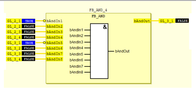
Predefined Safety Function Blocks
The CODESYS library describes pre-defined and factory-safe certified safety function blocks in safety logic modules for use in the FBD editor.
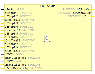
FB_ESTOP
The FB_EStop function block can be used to implement an emergency stop circuit with up to eight emergency stop inputs (bEStopIn1 to bEStopIn8). Each of the eight inputs can be negated using the “Negation” command in the context menu.
When an input requests a safe state, the first output (EStopOut) immediately enters the safe state (“0”) and the second output (EStopDelOut) enters the safe state after a configurable time delay.
FB outputs can be linked to several outputs, so that several immediate switch-off outputs (bEStopOut) or delayed switch-off outputs (bEStopDelOut) can be implemented with one FB_EStop. To terminate the safety state of an output, a 0->1->0 signal sequence must be recognised on the Restart input.
VAR_INPUT
| Variable | TYPE | Descriptions |
| bRestart | SAFEBOOL | At start (when the associated POU (TwinSAFE group) is started) or restart (when the input requests a safe state), the signal sequence 0->1->0 must be recognised on the Restart input before the safety state of the output is released. |
| bEStopIn1 | SAFEBOOL | 1st input channel: you can specify whether the input operates as a normally closed contact or as a normally open contact (make contact – safety state required in logic 1). |
| bEStopIn2 | SAFEBOOL | Second input channel signal. |
| tDiscTime12 | SAFETIME | Discrepancy time for input group 1 (In1+In2) |
| bEStopIn3 | SAFEBOOL | Third input channel signal. |
| bEStopIn4 | SAFEBOOL | Fourth input channel signal. |
| tDiscTime34 | SAFETIME | Discrepancy time for input group 2 (In3+In4) |
| bEStopIn5 | SAFEBOOL | Fifth input channel signal. |
| bEStopIn6 | SAFEBOOL | 6th input channel signal. |
| tDiscTime56 | SAFETIME | Discrepancy time for input group 3 (In5+In6) |
| bEStopIn7 | SAFEBOOL | Seventh input channel signal. |
| bEStopIn8 | SAFEBOOL | 8th input channel signal. |
| tDiscTime78 | SAFETIME | Discrepancy time for input group 4 (In7+In8) |
| bEDM1 | BOOL | bEDM1 is the feedback loop for the delayed output channel (bEStopOut). If this input is parameterised as active, the safety state of the output is only terminated on restart if bEDM1 supplies the signal “1”. |
| tEDM1ResetTime | SAFETIME | If it is not equal to t#0 ms, the timer starts after the output bEStopOut is switched on. If the bEDM1 input does not become FALSE within this time, a function block error is set and the output is switched off.This input is not supported by the EL6900. |
| bEDM2 | BOOL | same as in bEM1. |
| tEDM2ResetTime | SAFETIME | same as tEDM1ResetTime. |
VAR_OUTPUT
| Variable | TYPE | Descriptions |
| bEStopDelOut | BOOLSAFE | 1st output channel. Safety state corresponds to logic 0. |
| bEStopDelOut | BOOLSAFE | Second output channel; the safety state corresponds to logic 0. The safety state is output delayed according to the parameterised delay time tEStopDelOutDelay. |
| bError | BOOLSAFE | FALSE: No error was detected. |
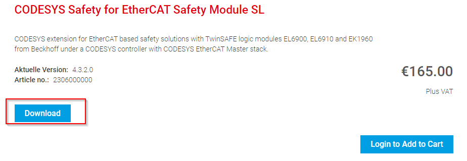
Download
Download the Add-on for CODESYS Safety for EtherCAT Safety Module SL from the Link below.
https://store.codesys.com/en/codesys-safety-for-ethercat-safety-module-for-el6900-sl.html
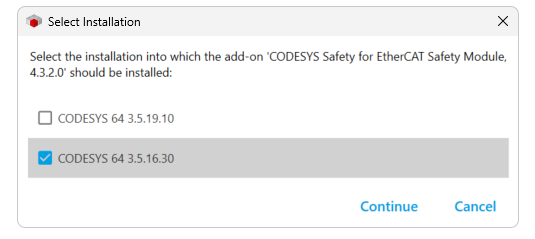
Install Packages
Select the CODESYS that Add-ons install and proceed with Continue.
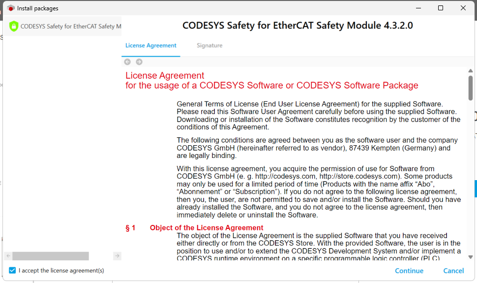
Agree to the license and proceed with Continue.
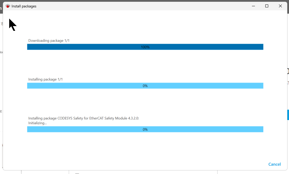
Just a second…
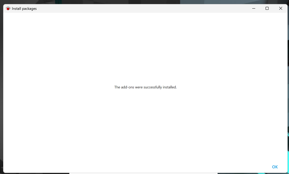
Done!
Implementation
Codesys Side
New Project
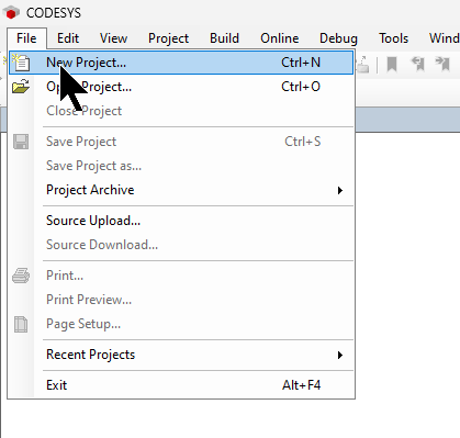
Create a new Codesys project under File>New Project.
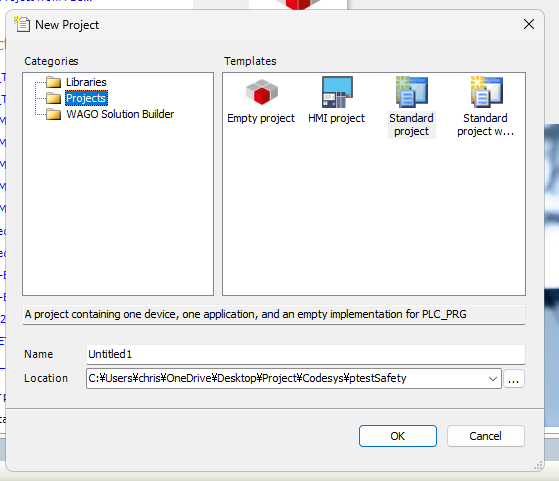
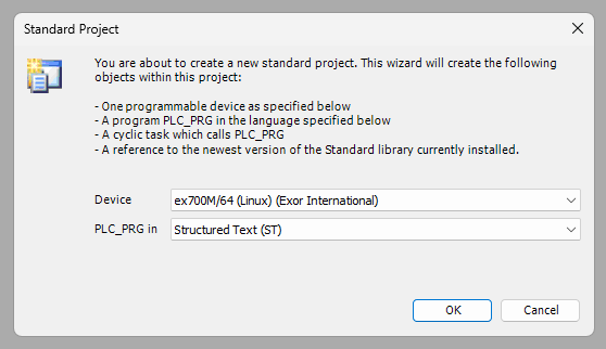
Select Standard Project > Enter a project name and press OK to proceed.
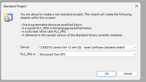
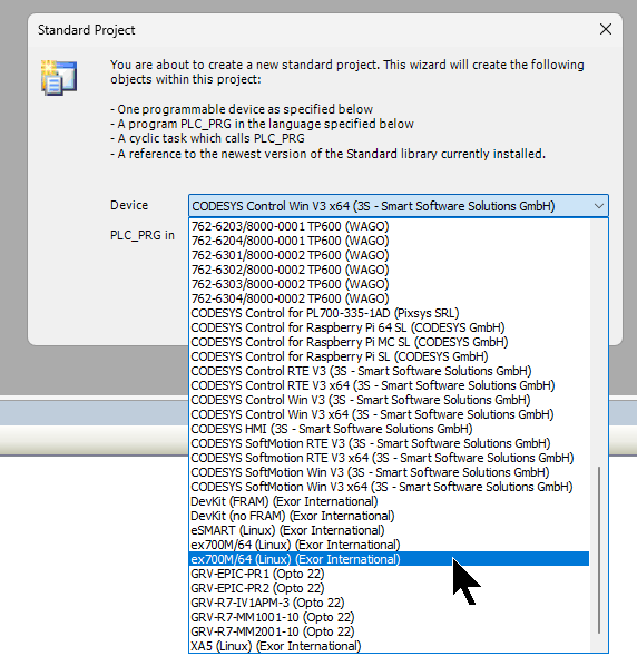
The next step is to configure the device on which the Codesys Runtime will run.
Since it is EXOR’s ex707M that will be used this time, select ex700M from Device.
Create a project in Ok.
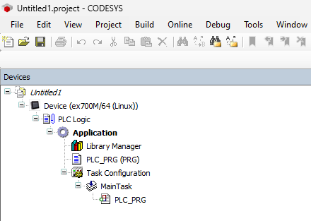
Done!A new project has been created.
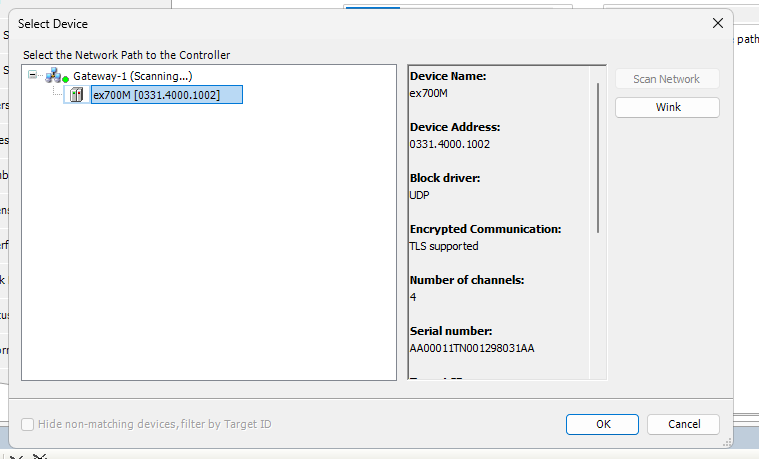
Scan For Network
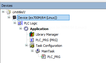
Next, double-click on Device to connect with Codesys Runtime.
Click on Scan Network and search for Codesys Runtime in EXOR.
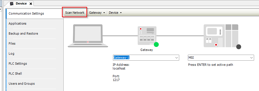
Done!
Configure EtherCAT
To add an EtherCAT Master, right-click on the device>Add Devices.
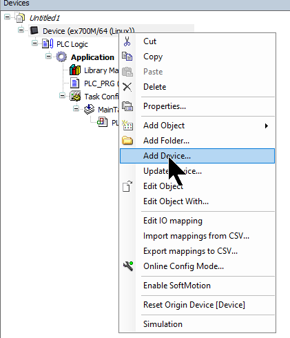
Add an EtherCAT Master by selecting Fieldbus>EtherCAT>Master>EtherCAT Master>Add Devices.
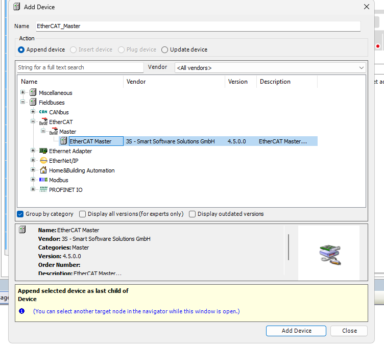
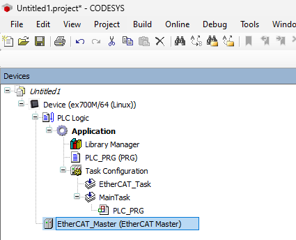
Done!EtherCAT Master has been added.
Install ESI File
To build an EtherCAT Slave, install the ESI File in the Codesys IDE.
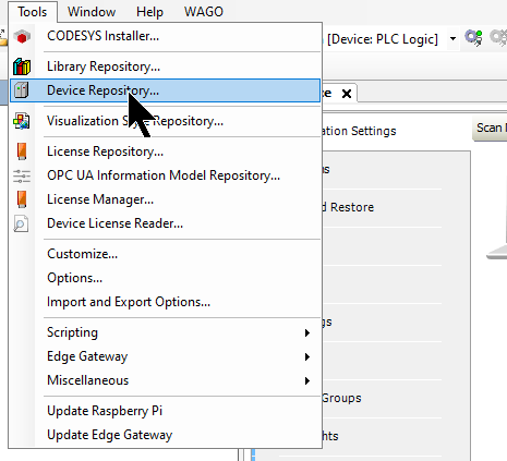
Click Tools>Device Repository.
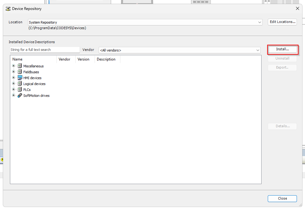
Click on the Install button and install the ESI File downloaded from Beckhoff HP.
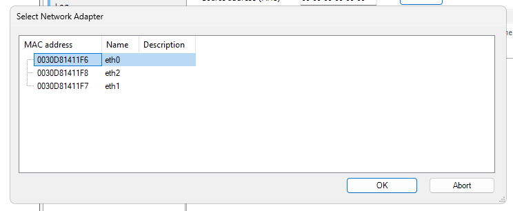
Configure Network Adapter
Next, click on the “Select” button to configure the EtherCAT Adapter to be used as EtherCAT Master.
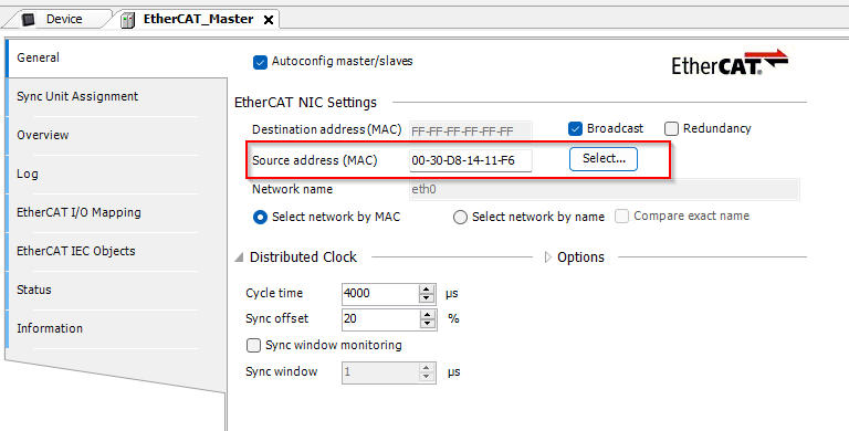
Set it up according to your application.
Scan Network
Slaves can be added one by one, or, if the ESI File is complete, it is also possible to search for EtherCAT slaves directly on the network.
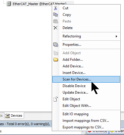
Click EtherCAT Master>right-click>Scan for Device.
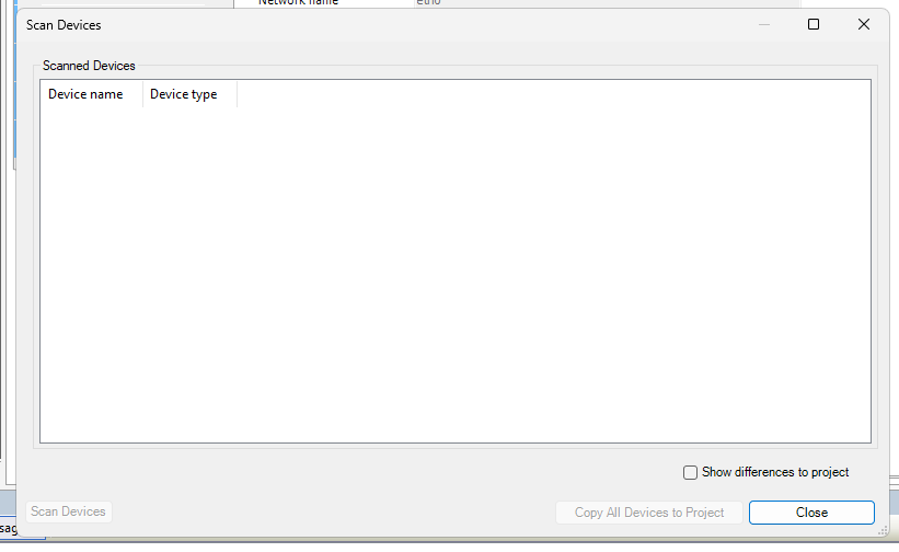
Wait a moment for the Codesys Scan Network screen to appear.
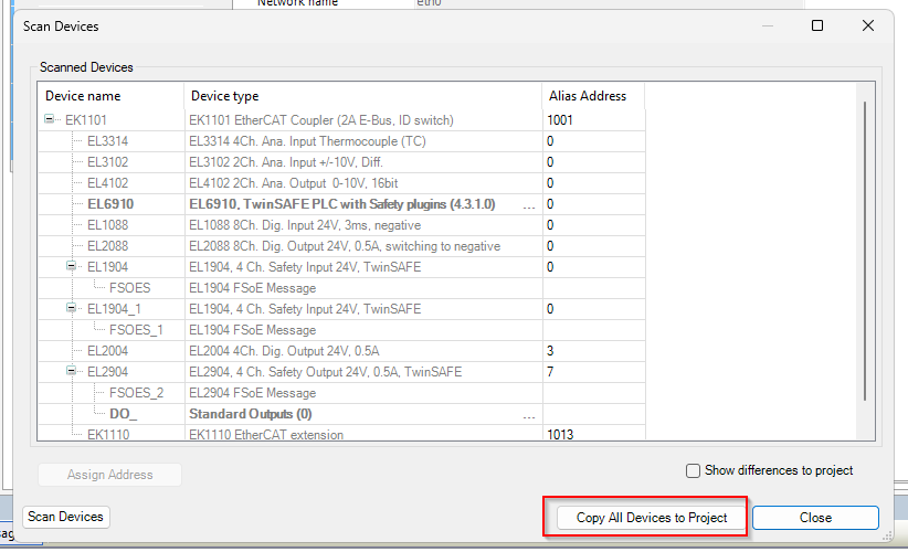
Done!Click on “Copy All Devices to Project” to copy the Slave information in the Codesys project.
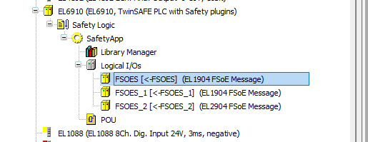
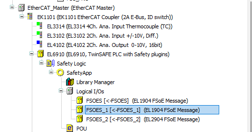
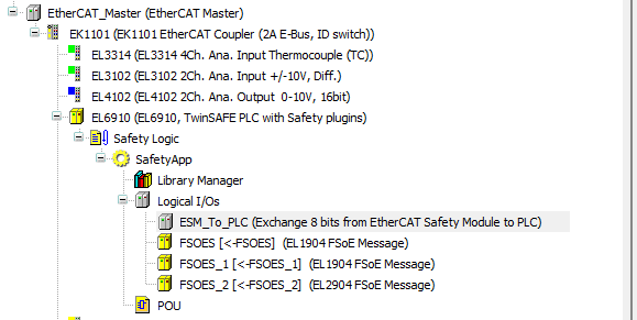
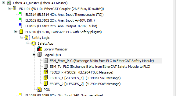
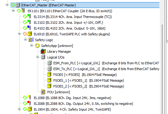
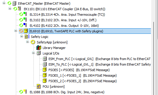
TwinSAFE with Safety plug-ins
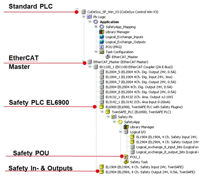
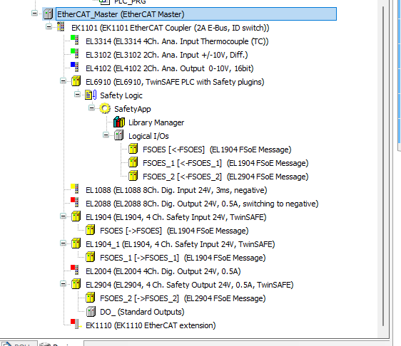
The EtherCAT safety modules EL6900 and EL6910 are added to the device tree under EtherCAT bus couplers (e.g. EK1100) ,and the EtherCAT safety module EK1960 to the device tree under EtherCAT masters.
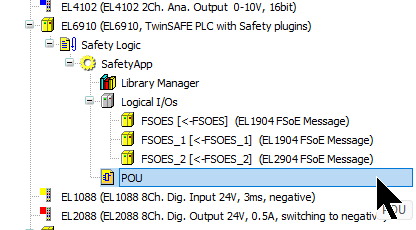
The logical node Safety Logic, the safety application object SafetyApp, the library manager and the node logical I/Os are then automatically added when the EtherCAT safety module is inserted.
The EtherCAT safety module can be updated to a newer version of the device description using the Update Device… command in the context menu to update the device description to a newer version. This also updates the library to the new version.
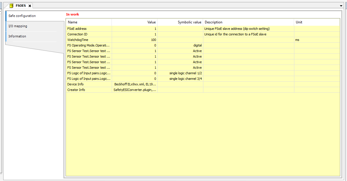
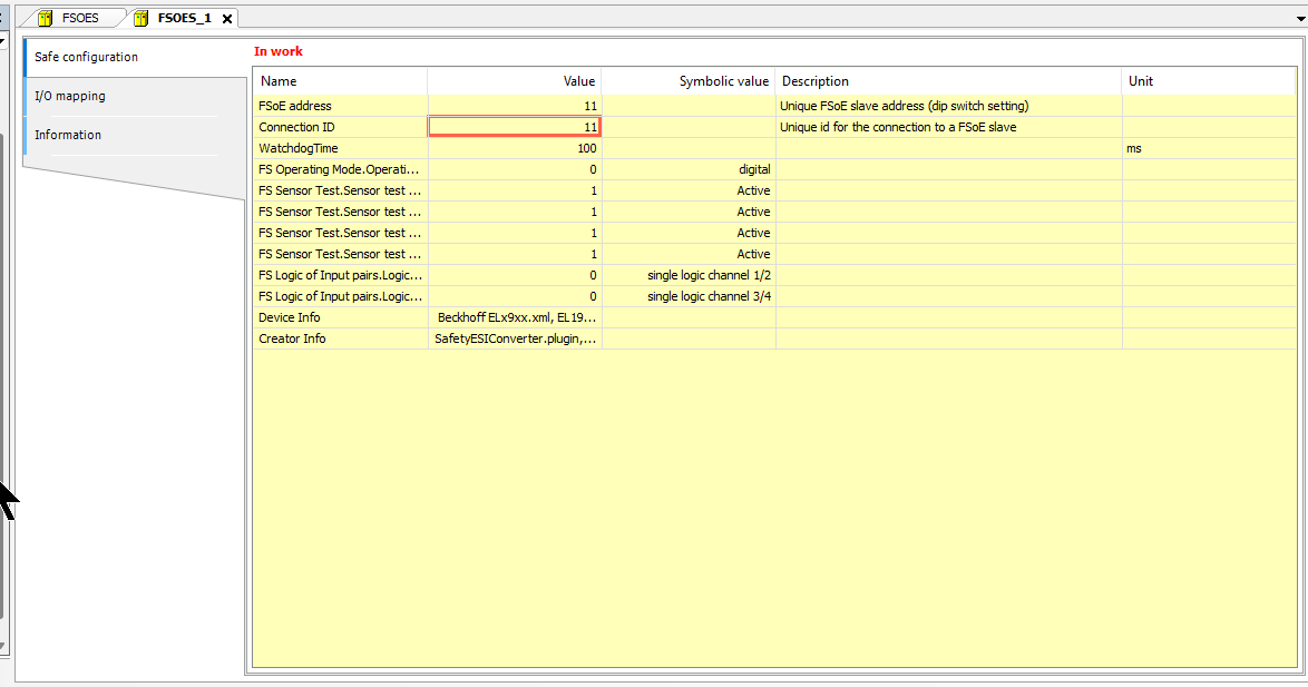
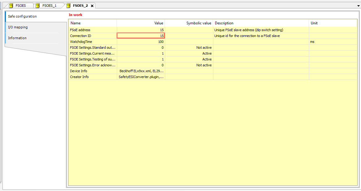
Safety Configuration
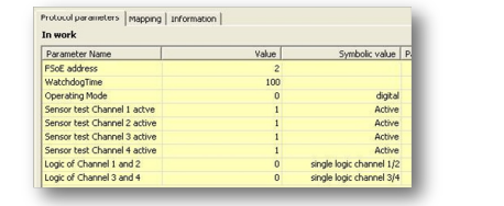
Now configure the settings for each FSOE Slave. At a minimum, set the following three parameters.
- FSoE address: unique EtherCAT address of the module; the FSoE connection corresponds in each case to a secure fieldbus device (or its logical I/O).
- WatchdogTime: If the module does not respond within this time, an error is output.
- Connection ID: unique connection number for the entire EtherCAT network
EL1904 Slot1
Initially, click Logical I/O>FSOE to configure the first EL1904.
This is the FSOE Slave parameter screen.
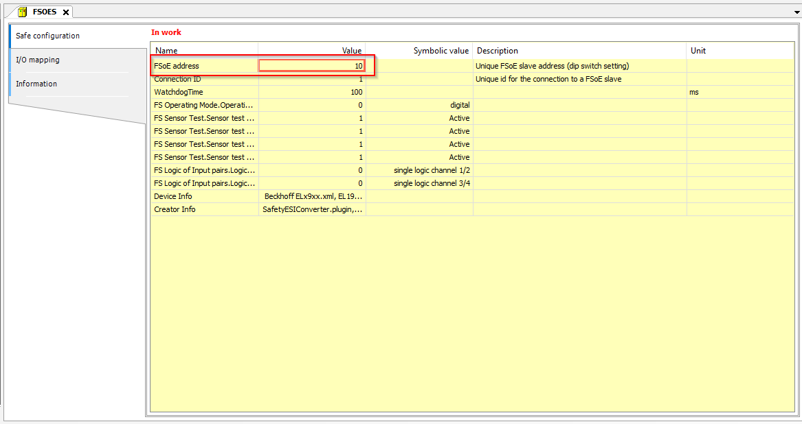
FSoE Address
The FSoE address of the EL1904 can be set via DIP switches on the module itself.
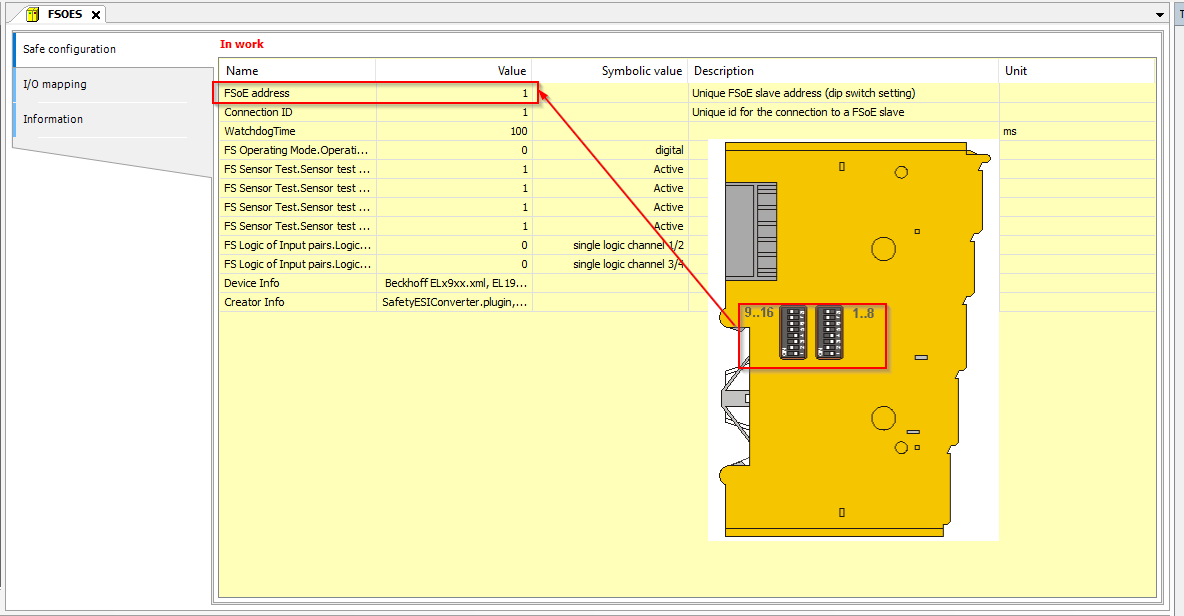
Enter the DIP switches according to their settings.
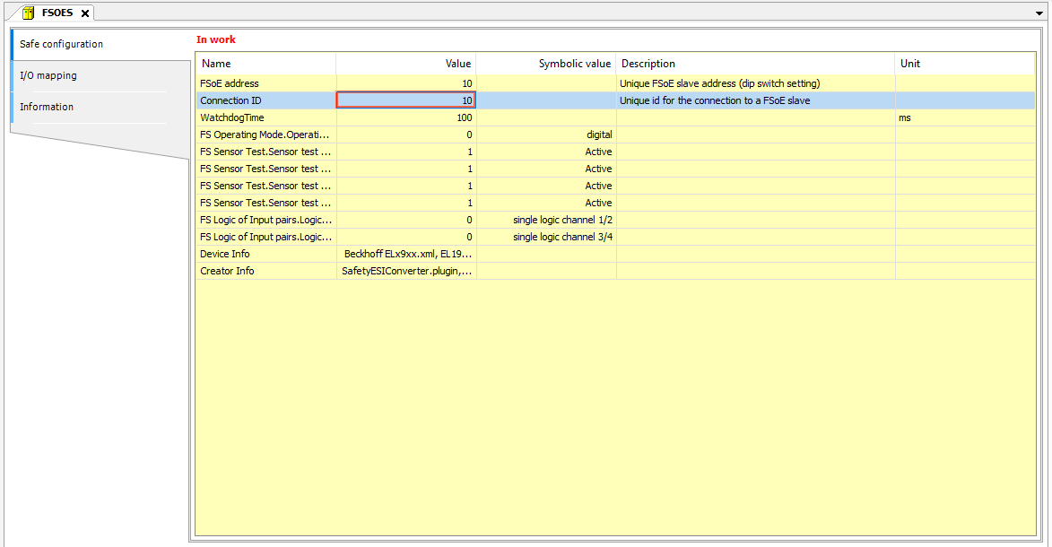
Connection ID
The next step is to set the FSOE network connection number.
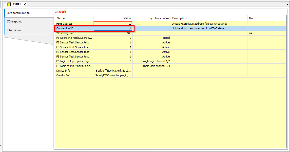
Please set this number so that it does not overlap. This time, match it to the FSOE address in the same way.
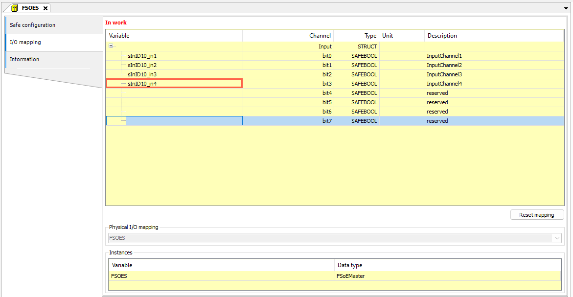
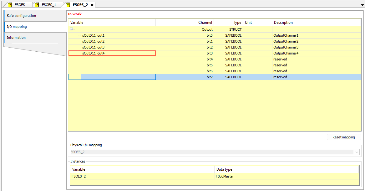
Mapping
Define the Process data for the safety module on the Mapping screen here.
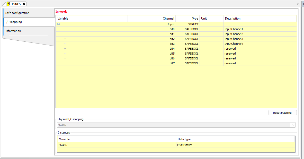
you can put variables in the Variable Field as shown in the diagram below.
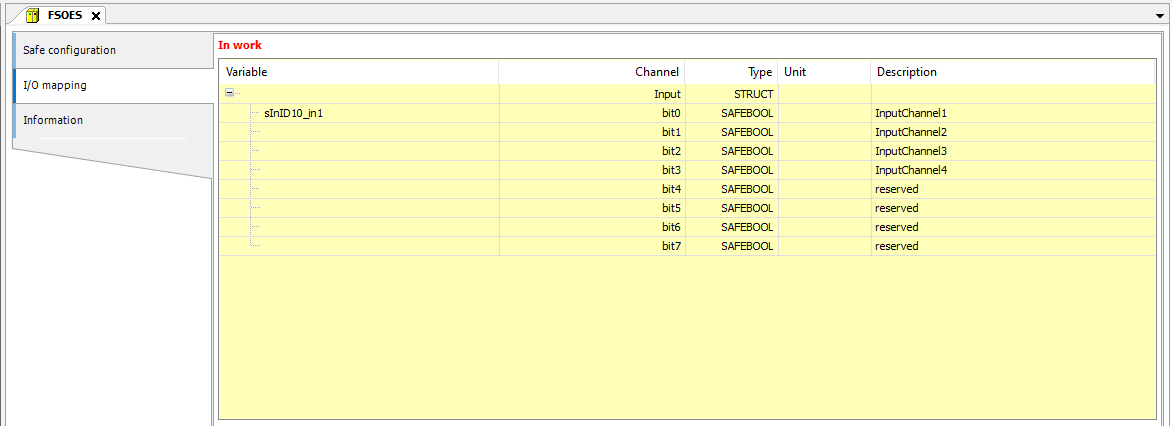
Done!
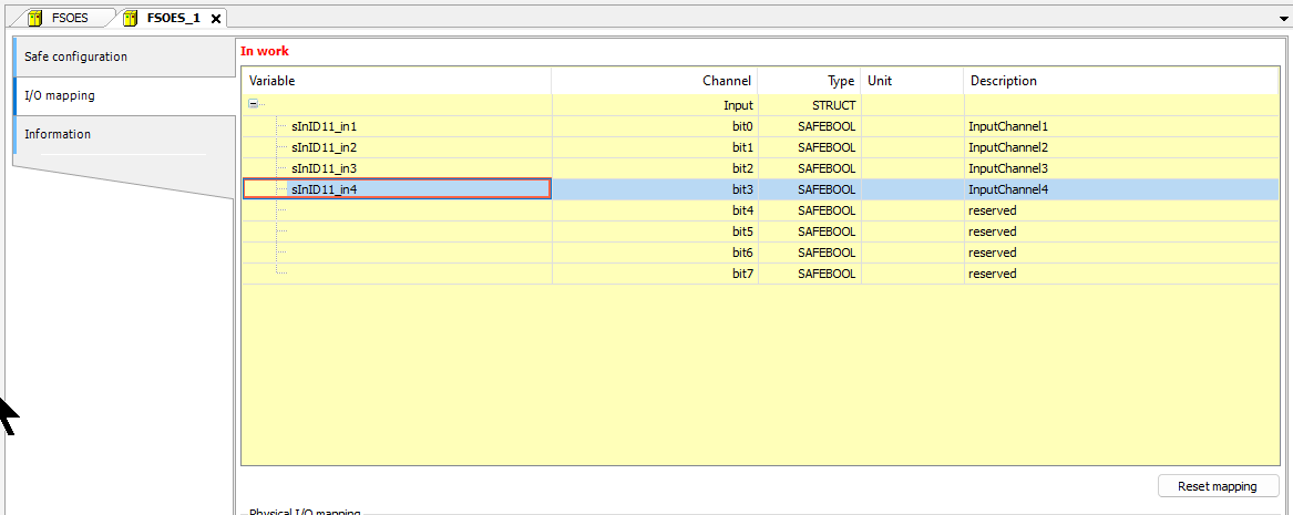
EL1904 Slot2
Next, click Logical I/O>FSOE_1 to configure the second EL1904.
FSoE Address/Connection ID
Set the FSoE address and Connection ID correctly.
Mapping
Then define the variables you need for your application.
EL2904 Slot3
Finally, to configure the third EL2904, click Logical I/O>FSOE_2.

FSoE Address/Connection ID
Set the FSoE address and Connection ID correctly.
Mapping
Then define the variables you need for your application.
Local I/O Configuration
Once you have completed the configuration of the safety configuration, it is now time for the Local I/O Configuration. First of all, it is not possible to insert hardware modules under the EtherCAT safety module. Safety modules and standard modules are inserted in the device tree under the coupler (e.g. EK1100) and the connection and data exchange with the EtherCAT safety module takes place via so-called logical I/Os. These objects are inserted under the logical I/Os node.
Types of logical I/Os
CODESYS distinguishes between two different types of logical I/Os.
logical I/Os of safe field devices
If a safety field device is inserted in the device tree and only one EtherCAT Safety module is present, a matching logical I/O is automatically inserted (same name as the I/O module).
If several EtherCAT Safety modules are used, the corresponding logical I/Os have to be added manually. This logical I/O must then be selected in the I/O mapping dialog of the corresponding field device. The logical I/O contains all safety parameters of the module and all safety-related information can be viewed in the safety application.
logical I/Os of global variables
Additional data can be exchanged between the EtherCAT Safety Module and the standard controller via these objects. For this purpose, global variables (GVL for logical exchange) are defined in the standard project and connected to the corresponding logical I/Os on the EtherCAT Safety Module (logical exchange device).
(see Logical I/O for Exchange of Data with the Standard Controllers)
The logical I/Os of the safety application are linked to the default application by physical devices or logical exchange GVLs (special objects on the standard side). This means that for each physical device whose input and output signals are processed by the safety application, there is exactly one logical I/O in the safety application. Similarly, for each GVL there is exactly one logical I/O under the safety application for the logical exchange of standard controllers.
Advantages of the logical I/Os
The logical I/O concept offers the following advantages for the development and validation of “CODESYS Safety for EtherCAT Safety Module” safety applications.
- The parameterisation of the safety parameters of the field device (F-parameters of PROFIsafe) only takes place in the logical I/O of the safety application. If safety user management is configured, this parameterisation can only be performed by members of the Safety user group.
- Changing the allocation of physical field devices and GVLs for logical exchange does not change the safety application.
- An already validated and approved safety application can be detached from the original project and fully integrated into another project without having to validate this new safety application again.
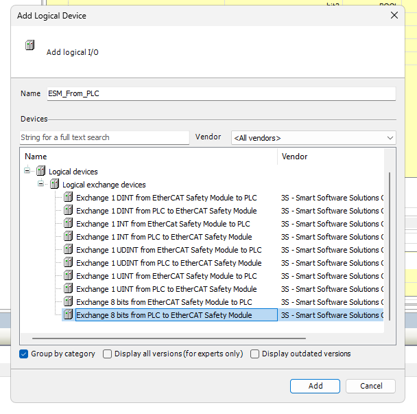
Add Logical Device
To add a Logical Device, click Logical I/Os>Add Object>Logical Device.
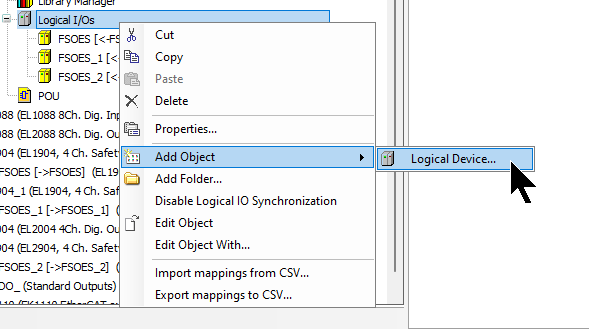
The Add Logical Devices screen appears.
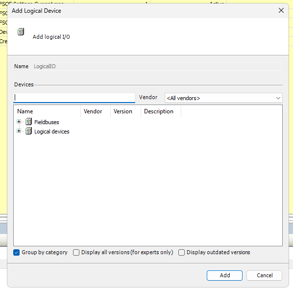
8 Bits From Module to PLC
First select “Exchange 8 bits from EtherCAT safety Module to PLC” to add a Slot to be sent from the EtherCAT Safety Module to a standard PLC, then add the Slot with Add Add to add a Slot.
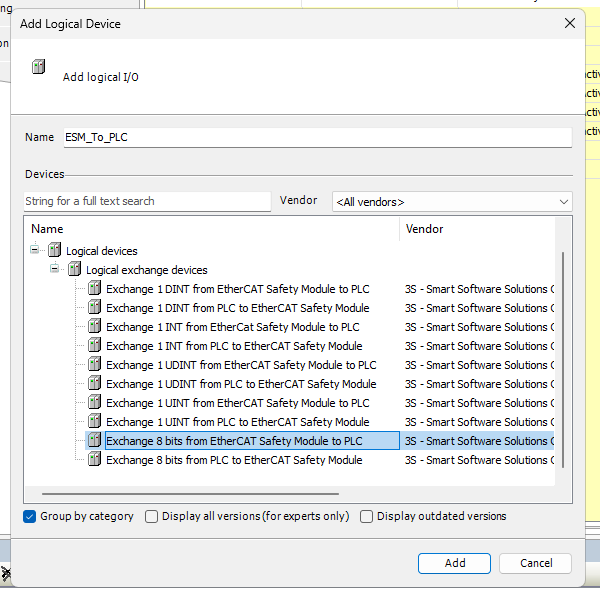
Done!
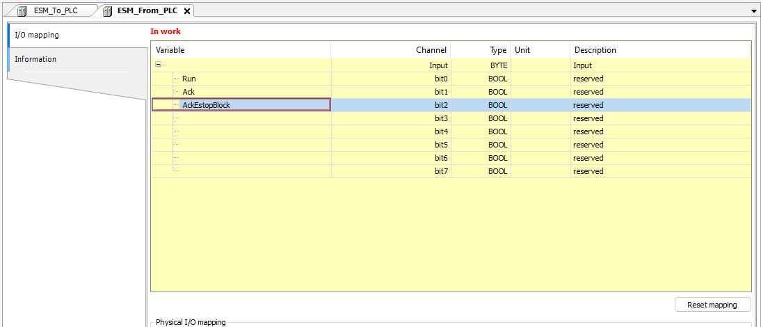
Mapping
Open the I/O Mapping screen and define variables using the same operation as in FSoE earlier.
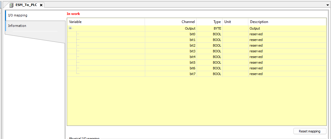
Done!
8 Bits From PLC to Module
Now select “Exchange 8 bits from PLC to EtherCAT safety Module” to add a Slot to be sent from the standard PLC to the EtherCAT Safety Module and add the Slot with Add. Add.
Done!
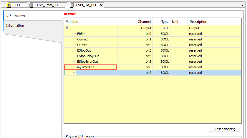
Mapping
Open the I/O Mapping screen and define variables using the same operation as in FSoE earlier.
Safety Program
Now that you have reached this point, it is time to add the safety program.
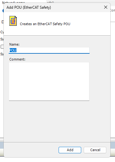
Click on SafetyApp>Add Object>POU(EtherCAT Safety).
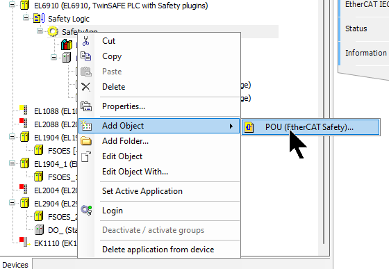
Enter the name of the safety programme and add the programme with Add.
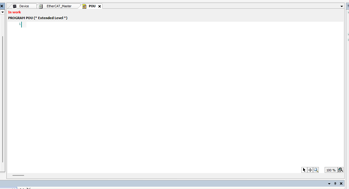
Done!
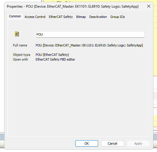
This is the Codesys safety programme IDE.
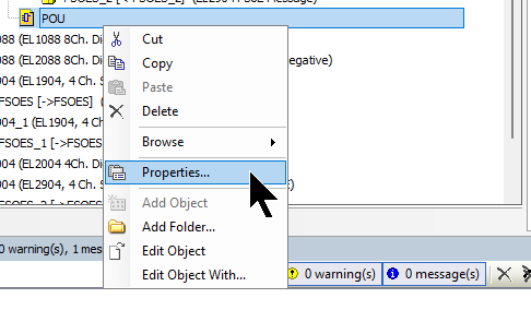
Properties
Before creating the safety programme, we need to set up the Properties of the POU.
The settings are exactly the same as when using TwinSAFE with the Beckhoff TwinCAT3.
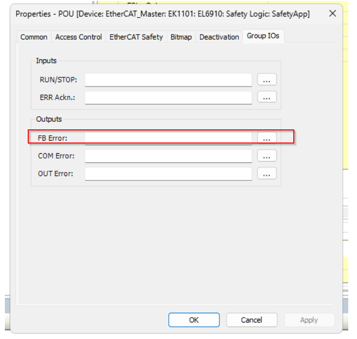
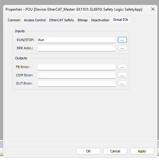
Open the Group IOs tab. Here you need to Mapping some Inputs/Outputs.
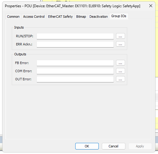
Inputs
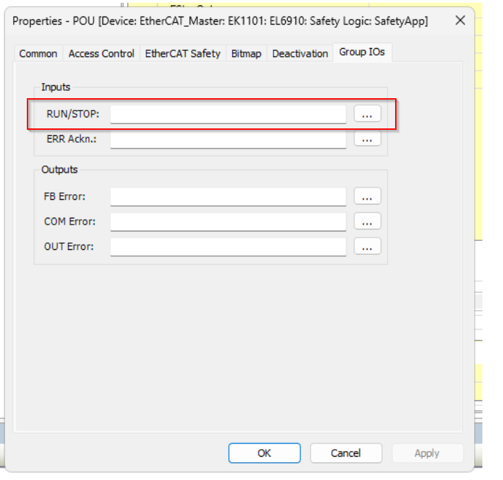
RUN/STOP
Variables that can start or stop the processing of POUs (optional)
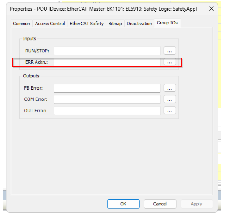
ERR Ack
Variables to reset errors (must be defined)
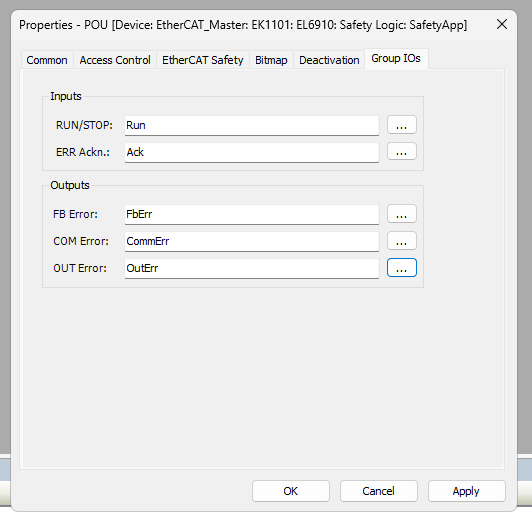
Outputs
FB Error
Variable for displaying function block errors (optional).
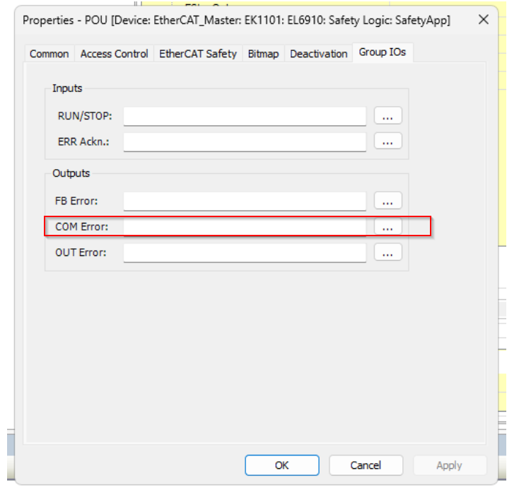
COM Error
Variables for which communication errors are displayed. (Optional)
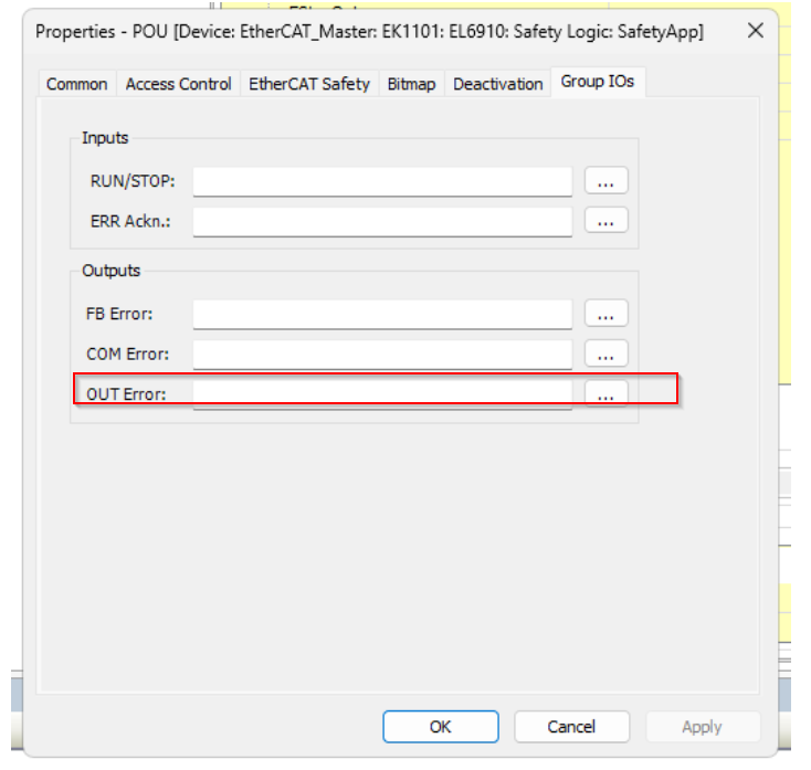
OUT Error
Variables with local output errors (KL6904 only) (optional)
Mapping
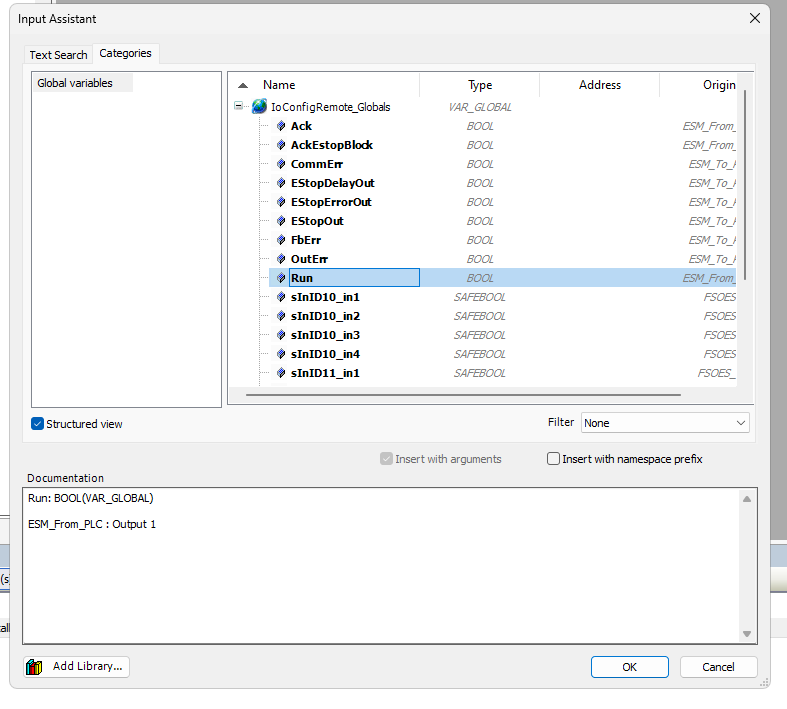
To Mapping those Group IOs variables, click on the … button next to each variable.
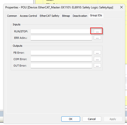
The Mapping screen appears as usual and you can select from the Logical I/Os you have just defined.
Done!
Define all Group IOs as shown below.
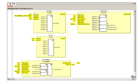
Program
Now we can start to create the safety program.
Network1
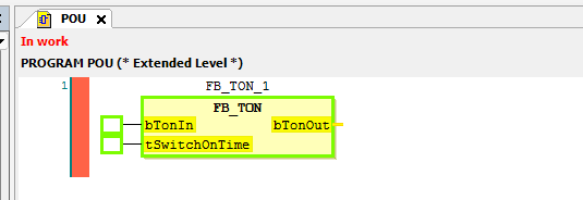
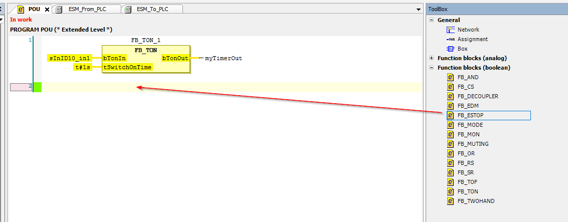
To add a Safety Function Block from the Network, you can drop the library in the Toolbox directly into the Network as shown in the diagram below.
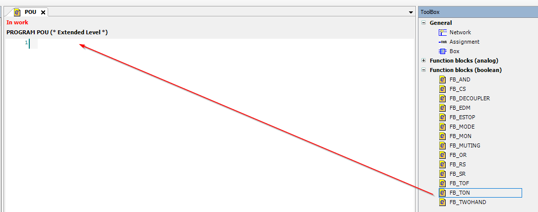
Done!Network1 has added a TON Timer for Safety.
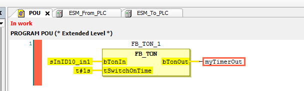
Then you can link all parameters as same as normal program.
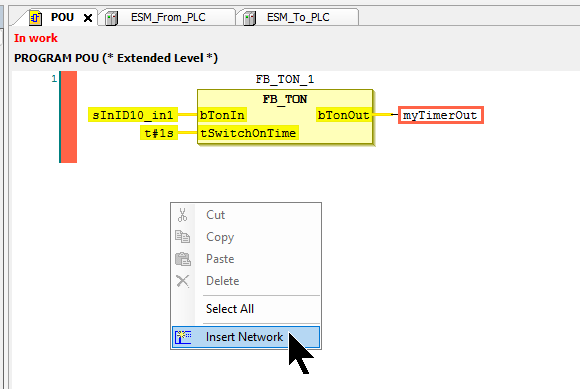
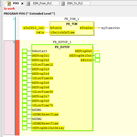
Network2
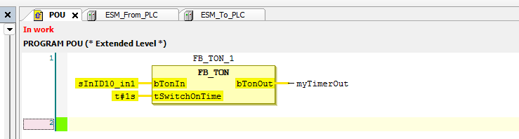
To add a Network, right-click in the margin of the IDE > Insert Network to add a new network.
Done!
Now let’s drop FB_ESTOP to add a Function Block that controls the emergency stop.
Done!
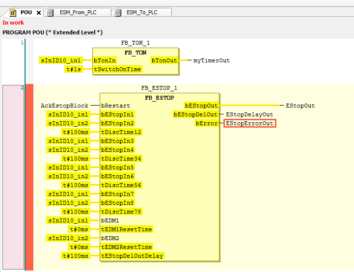
Define all input and output parameters.
Non-Safety Program
The last step is to add a program on the standard PLC side.
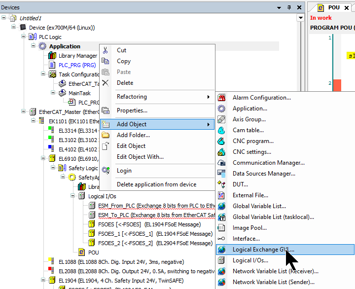
Add Logical Exchange GVL
You have just defined Logical I/Os with EL6910, but you need to use the Logical Exchange GVL to exchange those data with a standard PLC.
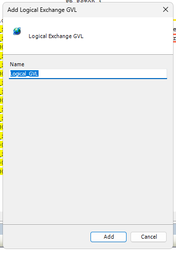
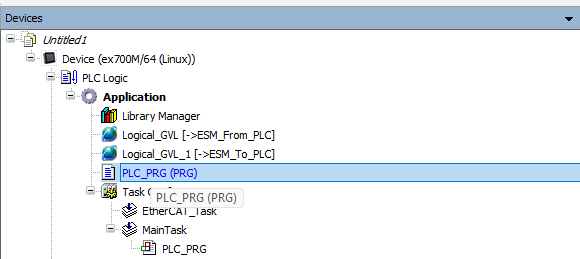
Add a GVL at Add Object>Logical Exchange GVL.
Enter the name of the Logical Exchange GVL and add the GVL with Add Button.
Done!
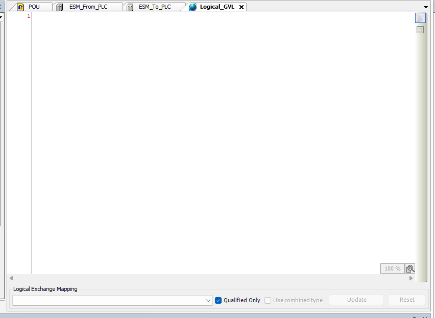
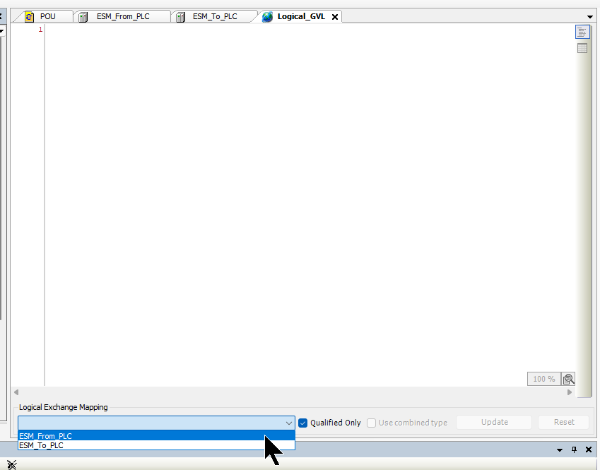
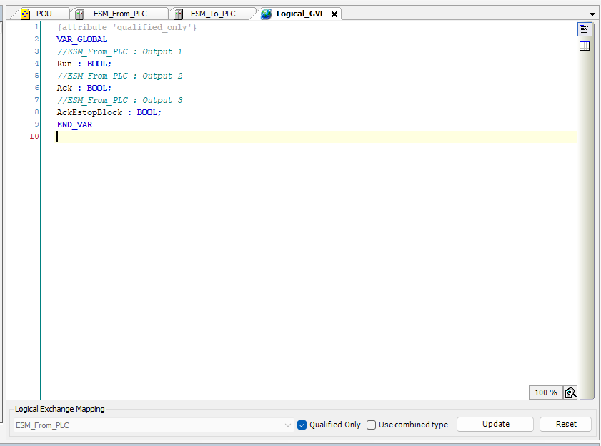
Next, select ESM_From_PLC from the Logical Exchange Mapping drop-list.
Done!The Logical I/Os variable that was just added automatically defined all the Codesys.
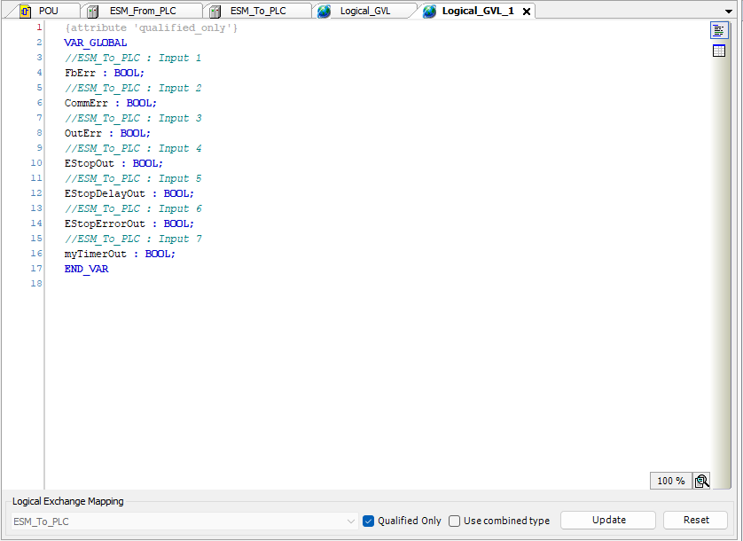
Next, select ESM_TOo_PLC from the Logical Exchange Mapping drop-list.
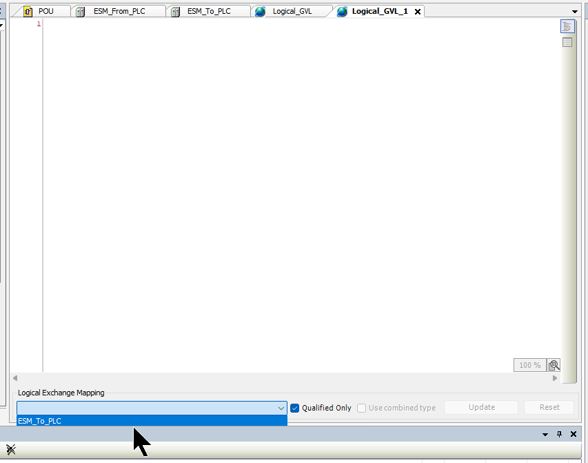
Done!All the necessary variables were automatically defined with almost no manual input.
Program
I will create some sample program in here.
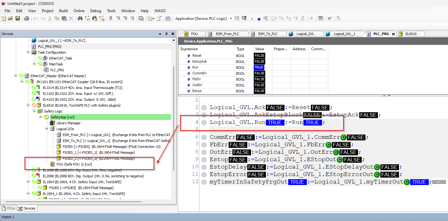
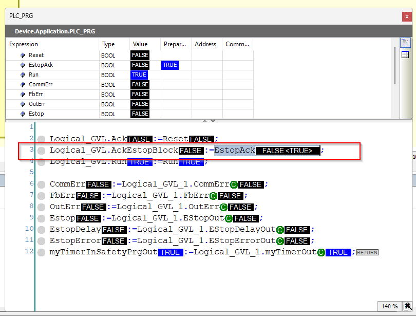
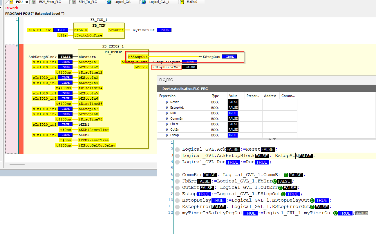
| PROGRAM PLC_PRG VAR Reset,EstopAck:BOOL; Run:BOOL; CommErr,FbErr,OutErr:BOOL; Estop,EstopDelay,EstopError:BOOL; myTimerInSafetyPrgOut:BOOL; END_VAR Logical_GVL.Ack:=Reset; Logical_GVL.AckEstopBlock:=EstopAck; Logical_GVL.Run:=Run; CommErr:=Logical_GVL_1.CommErr; FbErr:=Logical_GVL_1.FbErr; OutErr:=Logical_GVL_1.OutErr; Estop:=Logical_GVL_1.EStopOut; EstopDelay:=Logical_GVL_1.EStopDelayOut; EstopError:=Logical_GVL_1.EStopErrorOut; myTimerInSafetyPrgOut:=Logical_GVL_1.myTimerOut; |
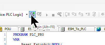
Login
Click on the Login button to Download the project to the EXOR panel.
Start
Click the Play button to run the application.
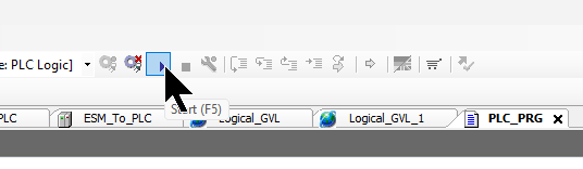
Done!The EtherCAT network came up successfully and all Nodes were recognised.
Download TwinSAFE Project
Finally, download the TwinSAFE project to EL6910.
Open the Safety Parameters Tab.
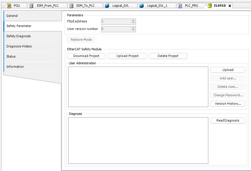
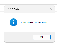
Click Download Project.
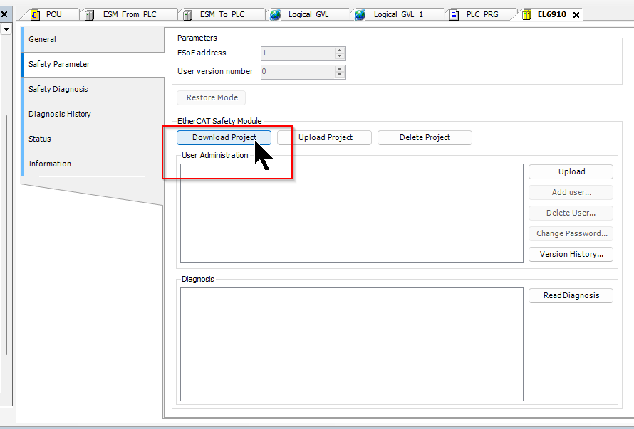
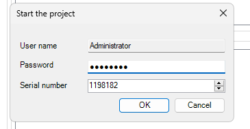
Before executing the command, a user must be selected from the user management. If no user is selected, “Administrator” will be used. This function is only available in online mode: after executing the Project Download command, the user must enter the password and the serial number of the terminal, otherwise the terminal will not accept data records.
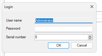
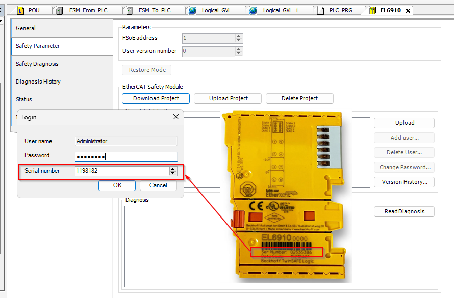
Password is TwinSAFE in Default and Serial Number can be found in the module.
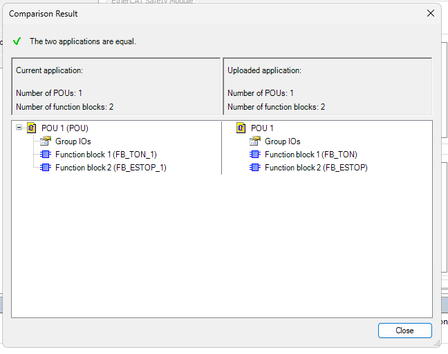
In order to check the generated code, a re-translation is automatically performed after the application is downloaded. For this purpose, the translated code is decompiled again and compared at source code level. This variety of methods ensures that the compiler’s functionality is checked at each download. Thereby, both random and systematic errors are determined.
The comparison results (same or different) are displayed to the user: for the EL6900, the number of POUs and networks compared; for the EL6910 and EK1960, the number of POUs and function blocks compared; for the EK1960, the number of POUs and function blocks compared.
Enter the Password and Serial Number again.
Done!!
Result
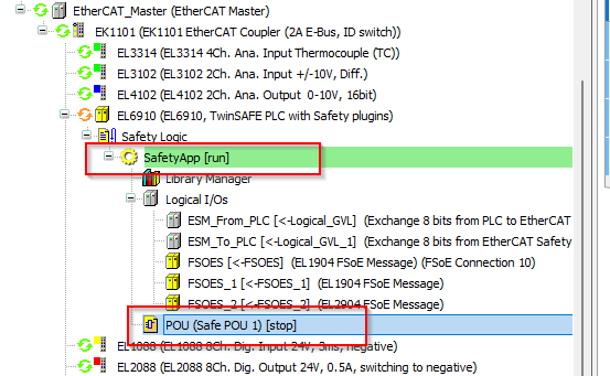
SafetyApp becomes Run and the POU changes to Stop.
Finally, setting the Run variable to True will also run the POU.
The next step is to reset the emergency stop Function Block FB_ESOTP, which requires a falling signal from AckEstopBlock.
Done!!
You can check the operation from this video.