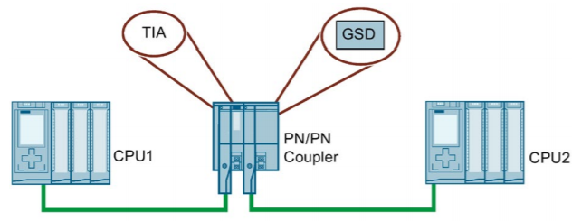
PNPN Coupler is a Devices for Profinet(Industrial Communication Protocol from Siemens)
Data Exchanges.This device allows 1440 Bytes Max. Inputs and 1440 Output Max. Outputs(in Firmware 4.0).
Note that it is not necessary to match the amount of input and output the same.(for example setup the inputs in 1200 bytes but 1440 bytes in outputs)
And Also,You can configure this configuration in the same step7 project/ separate projects.
In this post , I will explain how to configure it in separate projects.
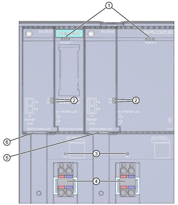
PN/PN Coupler outlook
Firstly, let’s explain some hardware parts of this PNPN Coupler.
- The LED to show the status ofX1,X2
- The status of Subnet1、2(X1、X2)
- The power supply status of PS1/PS2
- 24V DCSupply
- Profinet InterfaceX2
- Profinet InterfaceX1
Rules
While using PNPN Coupler to exchange the devices in the network, some rules that you need to clear in the both side(X1 and X2)
- Which device will use X1? Which device will use X2?
- time I will use S7-1200 to connect as X1, and Raspberry bease on Codesys will be connected as X2.
- 数Data Exchange
- S7-1200 Side
- IN:253 Bytes+DS
- OUT:253Bytes
- After we know the mapping, what we need to do on the raspberry side is – swap the In/Out order
- OUT:253Bytes
- IN:253 Bytes+DS
- The concept is , X1’s input is X2’s output, and X2’s output is X1’s input.
- S7-1200 Side
Here is the drawing of the Configurations:
Implementation
Now I will explain how to configure it.
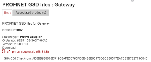
Please download the GSD files of PNPN Coupler in the follow link and install it.
Siemens Side
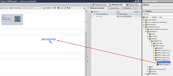
Open your Project, in the right side of Catalog > Other field devices>PROFINET IO>..
until you find the PN/PN Coupler V4.2.
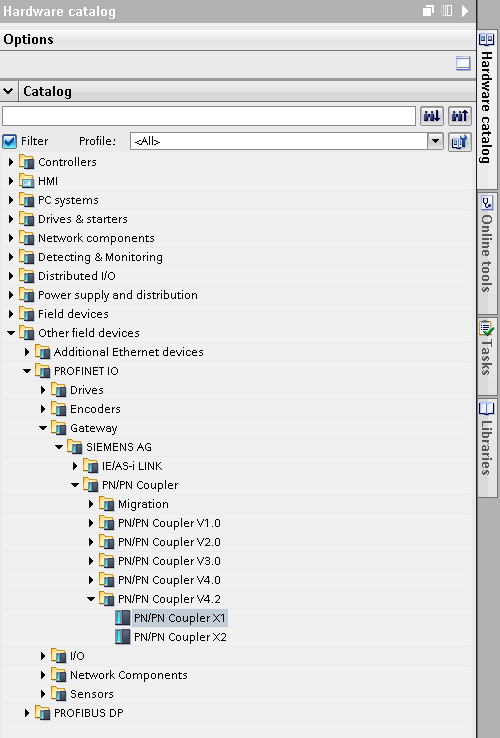
the PNPN Coupler X1 from right side to the network view side.
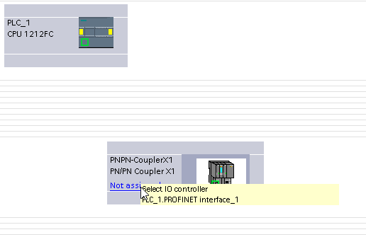
After that, the PNPN Coupler is inserted in your project. Edit the device name to match with your network drawing and Click the “No Assigned” Button>Select the S7-1200 Profinet Interface.
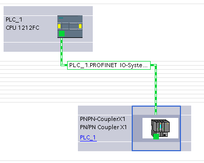
Now the S7-1200 is Connecced with the PNPN Coupler by Profinet.
Let’s switch back to the device view of the PNPN Coupler.
Drop the IN 253 Bytes+DS and OUT 253 Bytes items to your Modules Area.

Assign device name to your Devices.

Raspberry Side
Let’s install the GSD files that we downloaded before in the Codesys software.

Tools>Device Repository.
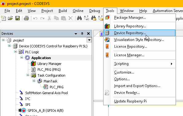
Install..

Choose the File that downloaded before in the Siemens website.

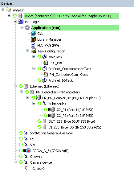
After GSD is installed, you can see the PNPN Coupler devices.

Ethernet>PN_Controller>Add Devices.
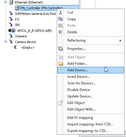
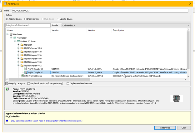
On the Siemens side we are using V4.2 – X1, now we will choose the same firmware version but X2. Then please press “Add Devices”.
Choose the PNPN_Coupler_X2> Right Click>Add Device

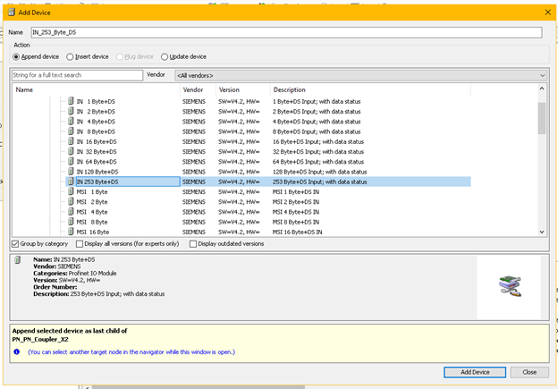
On the Siemens side, we configured INPUT then OUTPUT.
On the Raspberry Side, we need to swap this order.
So please insert the OUT first.

Then insert the IN side.
Let’s set-up the PNPN Coupler X2.
Choose the PNPN_CopulerX2.
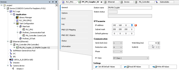
Set up the Ip address.
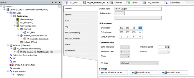
Surely if we are using profinet, Device Name is very important.(In Codesys they will name it as Station Name)

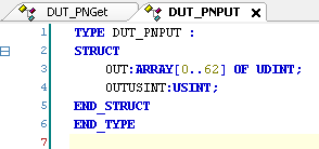
Define the memory area for the data exchanges by using the Data unit type.
DUT_PNGet is the Data from S7-1200.

DUT_PNPUT is the Data to S7-1200.
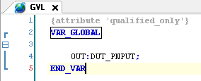
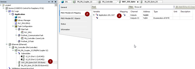
In the GVL(Global Variable List), define the DUT_PNPUT as OUT.
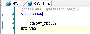
And define the DUT_PNGet as IN.
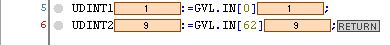
Now what we need to do, Mapping the variables that we defined before in the PN Configuration. Click IN_253bytes>PNIO Module I/O Mapping> Mapping.

Do the Same as on the OUTside.
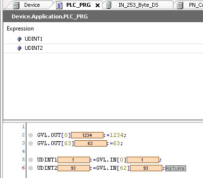
Write the simple test program.
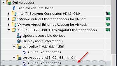
Open your TIA again, using Accessible devices tools to find the PNPN Coupler and select it>Show.

Project Tree in Left Side>Online access you can see the PNPN coupler.
Click the Online & diagnostics.
Assign the profinet name that you set in the Codesys project, then download the project to your Raspberry.
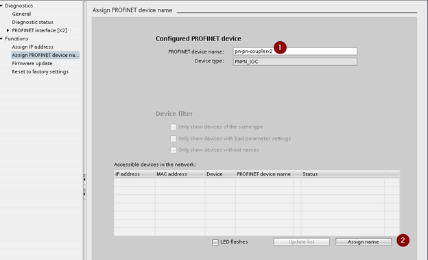
If there is no error in the network, you can see all green:)
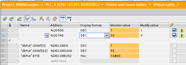
Test1
View the IO directly.

Test2
Let’s make some programs on the TIA Side.
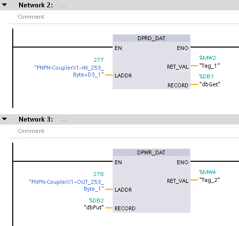
Open your OB1 and Insert the DPRD_DAT and DPWR_DAT.
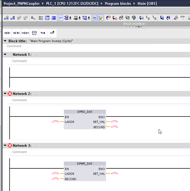
DPRD_DAT is a System Function Block to let you read the data from a Profinet Devices, refer to the LADDR and write inside the PLC sources(RECORD). please use F1 to see more.
DPWR_DAT is a System Function Block to let you write data to a Profinet ,refer to the LADDR,Source from RECORD.please use F1 to see more.
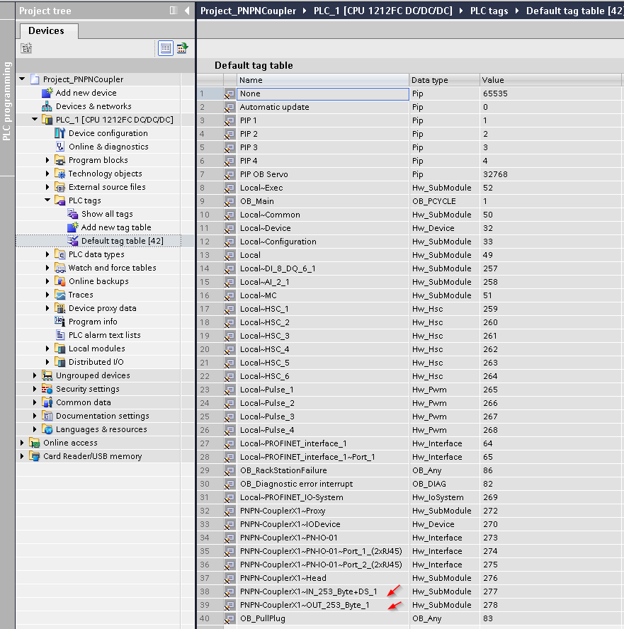
Here I will show you how to find the LADDR values for each Profinet Device.
PLC>PLC Tags>System Constants
Create the DB. it is just Same as what you done in Codesys Side.
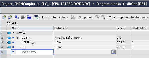
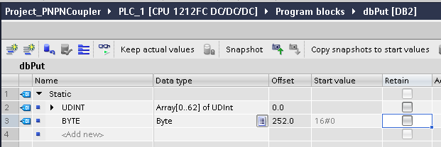
Finally, assign all the parameters in the Function Blocks.
Result

https://github.com/chwAmu/Codesys/tree/master/Profinet/Master
コメント
Hi,
You wrote “Poupler” to the title but I think you meant “Coupler”. I was wondering that is Poupler…
Thanks and I will correct it!!