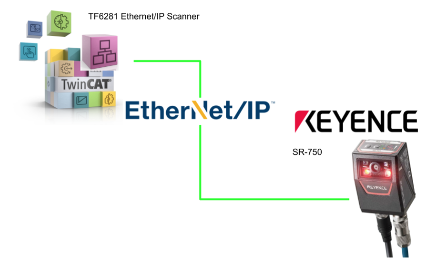
Here is an article about a new series from Keyence, the SR-750 series of compact 2D code readers! In this article, we will show you the simple setup required to use the SR-750, and how to connect and program the Beckhoff TwinCAT3 and Etherent/IP.
(From Youtube Channel Comment Request)
Let’s get started!
Reference Video
Beckhoff.Use Keyence SR750 with TwinCAT3 and Etherent/IP
SR750?
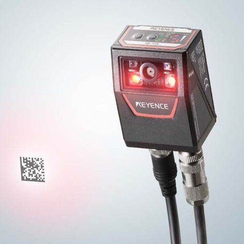
Despite its compact size, the SR-750 is capable of stable automatic reading of even difficult-to-read codes, and uses a new algorithm for acquisition and processing.
It thereby achieves best-in-class reading performance even for difficult-to-read codes, and can stably read codes printed directly on workpieces (DPM) made of various materials.
Tool Installation
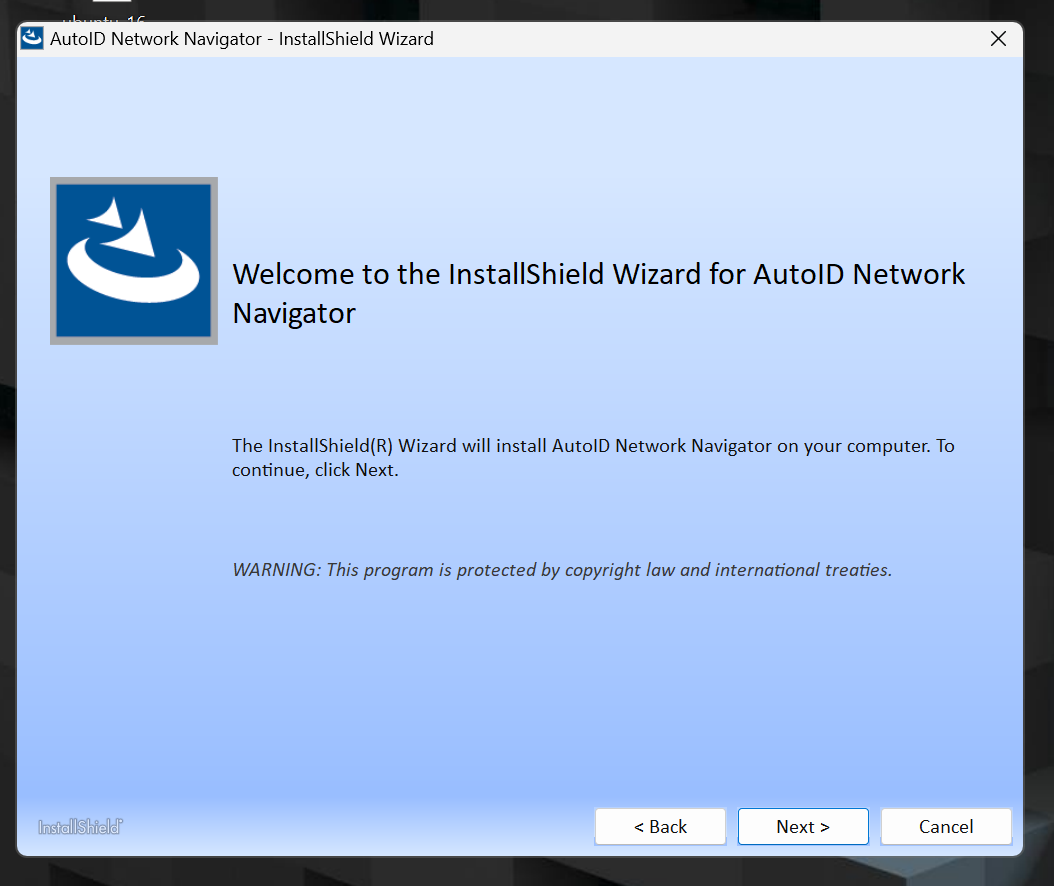
You need AutoID Network Navigator to set up the SR-750, so get the software from Keyence.
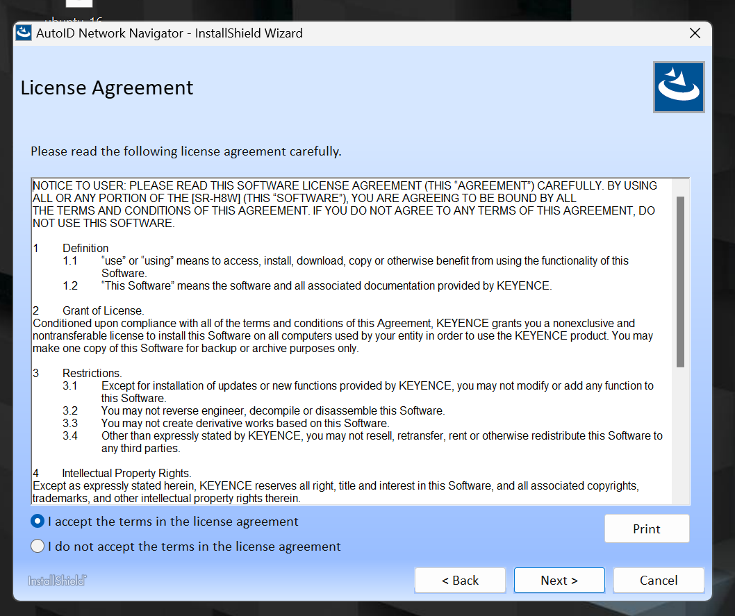
Agree to the license and proceed with Next>.
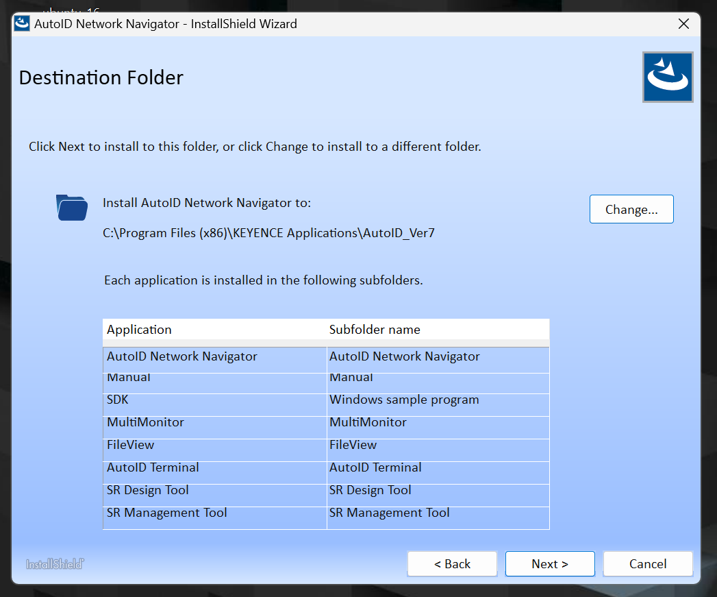
Proceed with Next>.
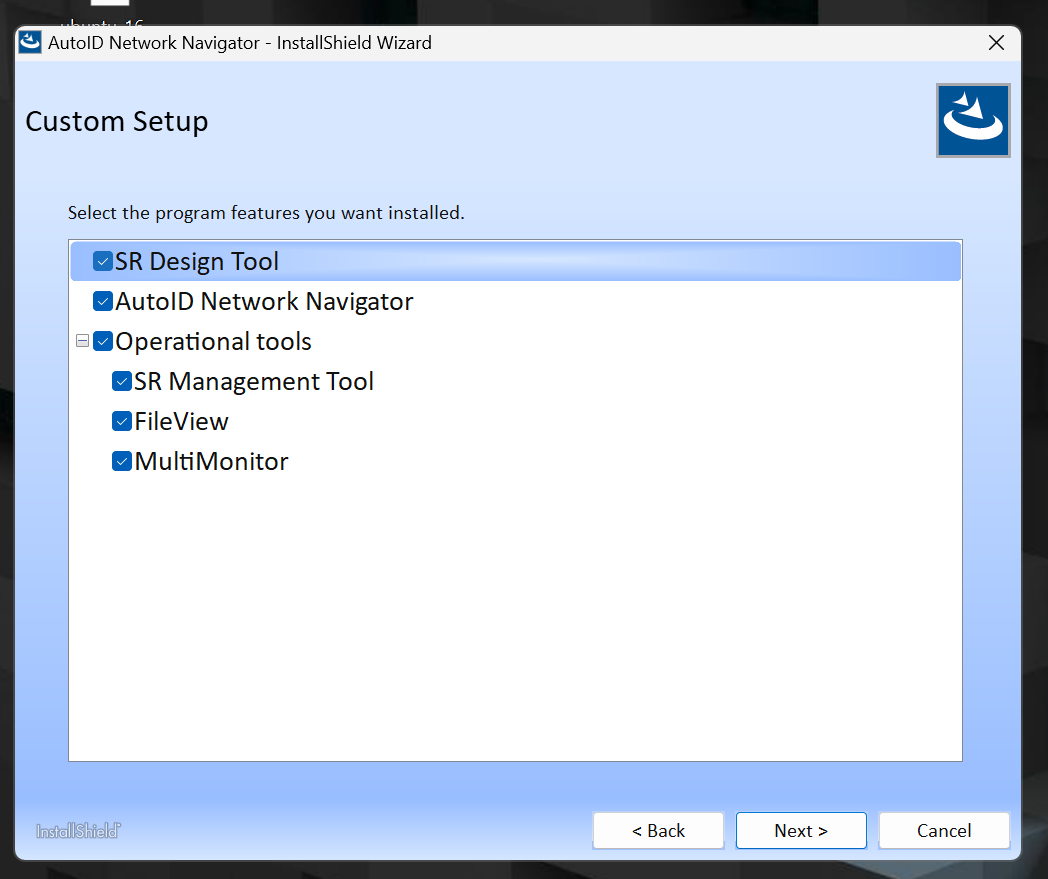
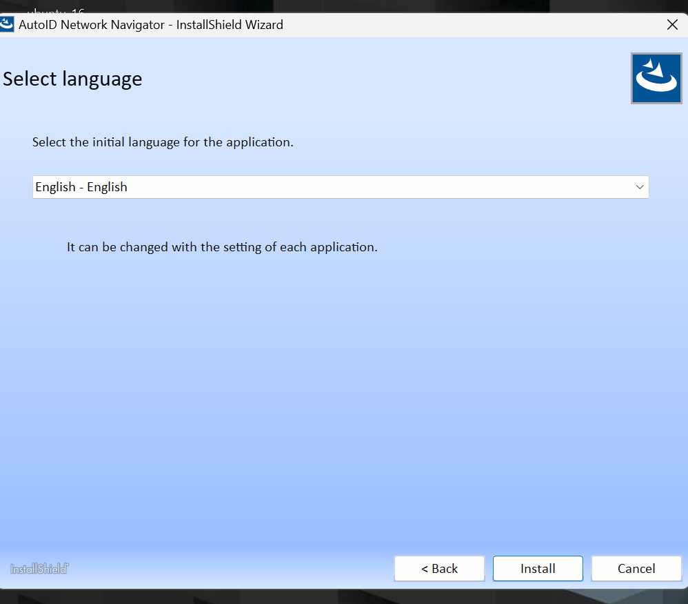
Select the software language and start Install.
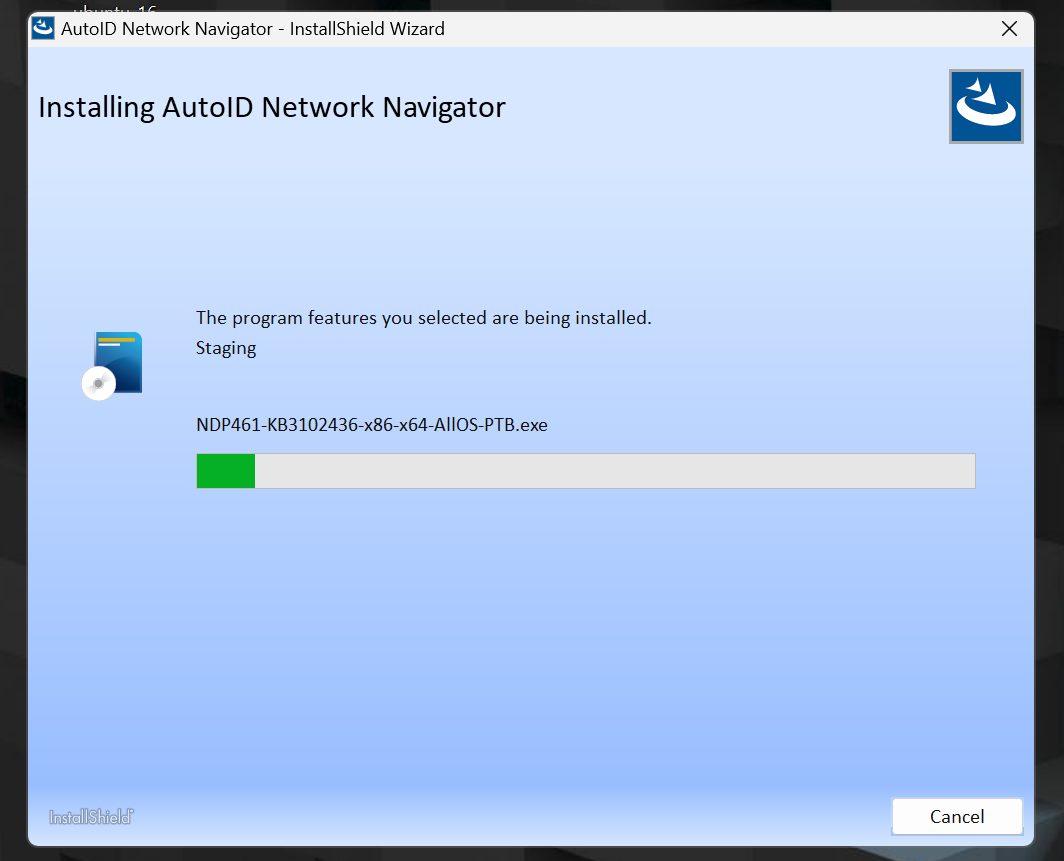
Just a second..
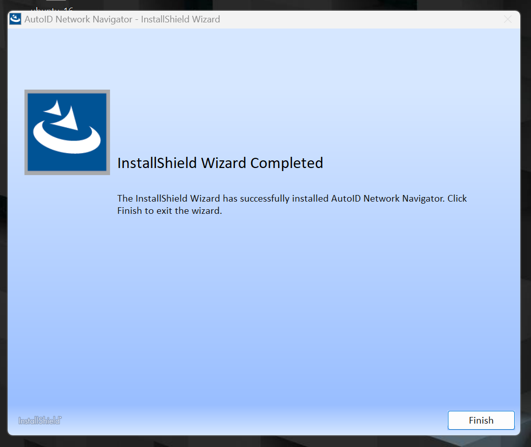
Done!
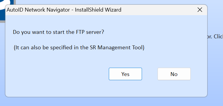
Do you want to start the FTP Server? No is OK for now.
Startup
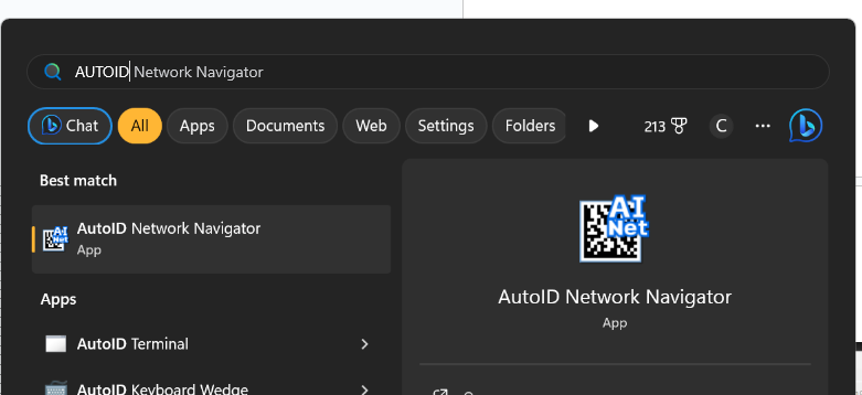
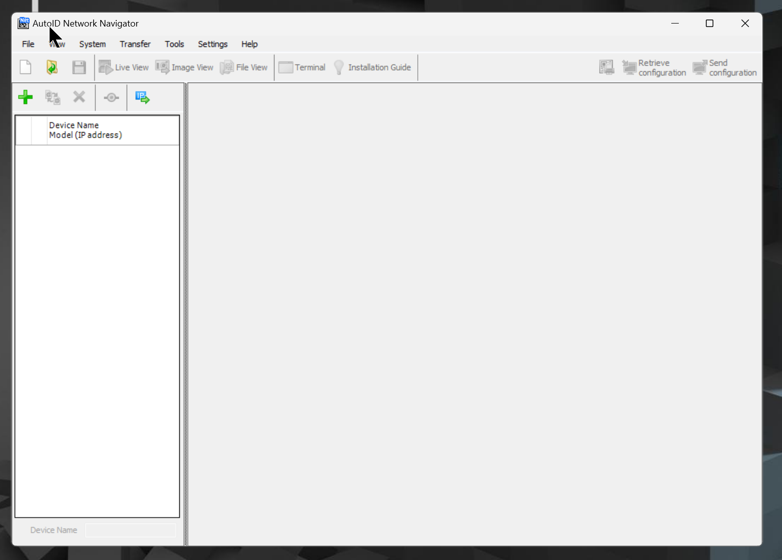
Launch AutoID Network Navigator.
Done!
Register Device
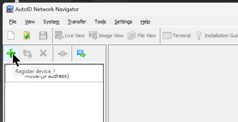
To connect to the SR-750 on hand, click the + button to register the device.
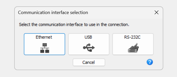
The screen for selecting the Interface to connect with SR-750 is displayed, this time connecting with Etherent.
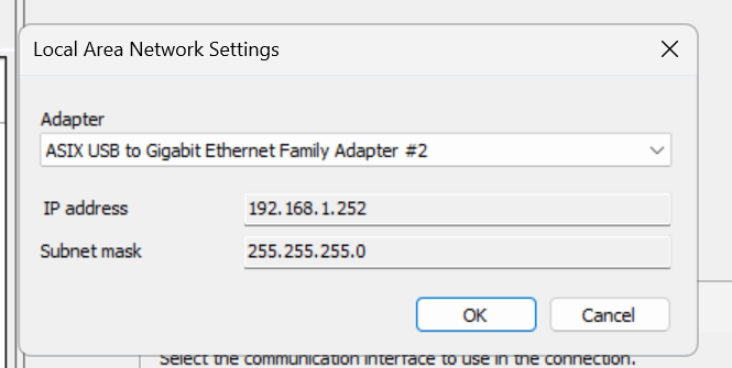
Next, configure the Interface of the PC.
By the way, the IP address of SR-750 is 192,168.100.100.
Next, the device search screen will appear, and you can use Auto Search to search for devices.
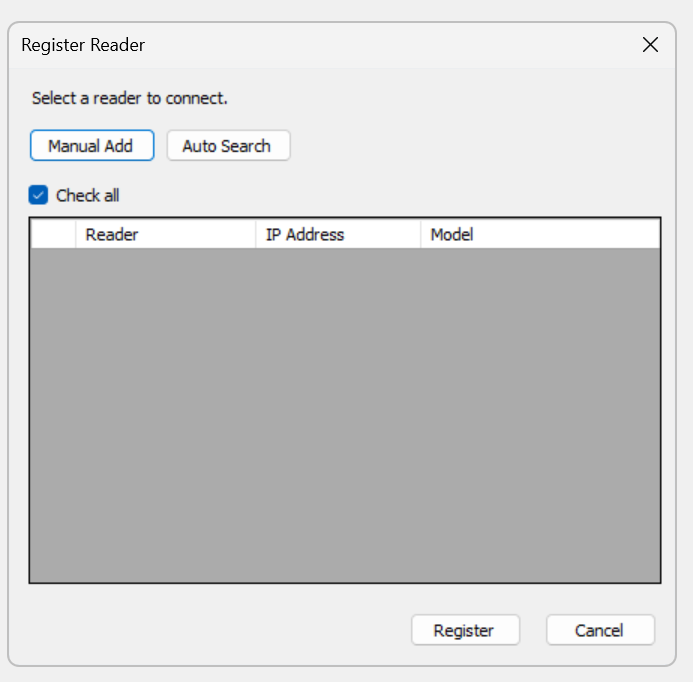
Done!SR-750 is found.
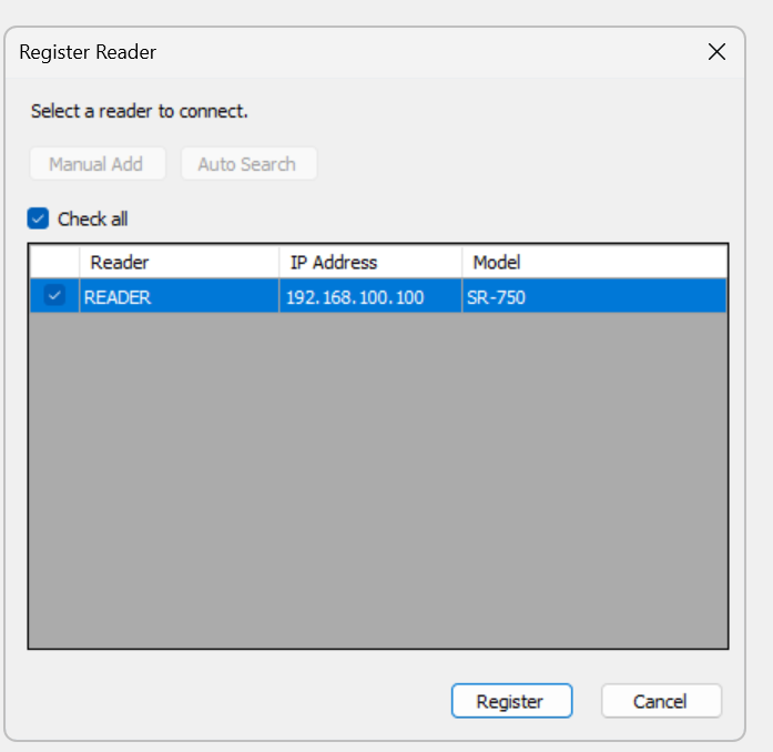
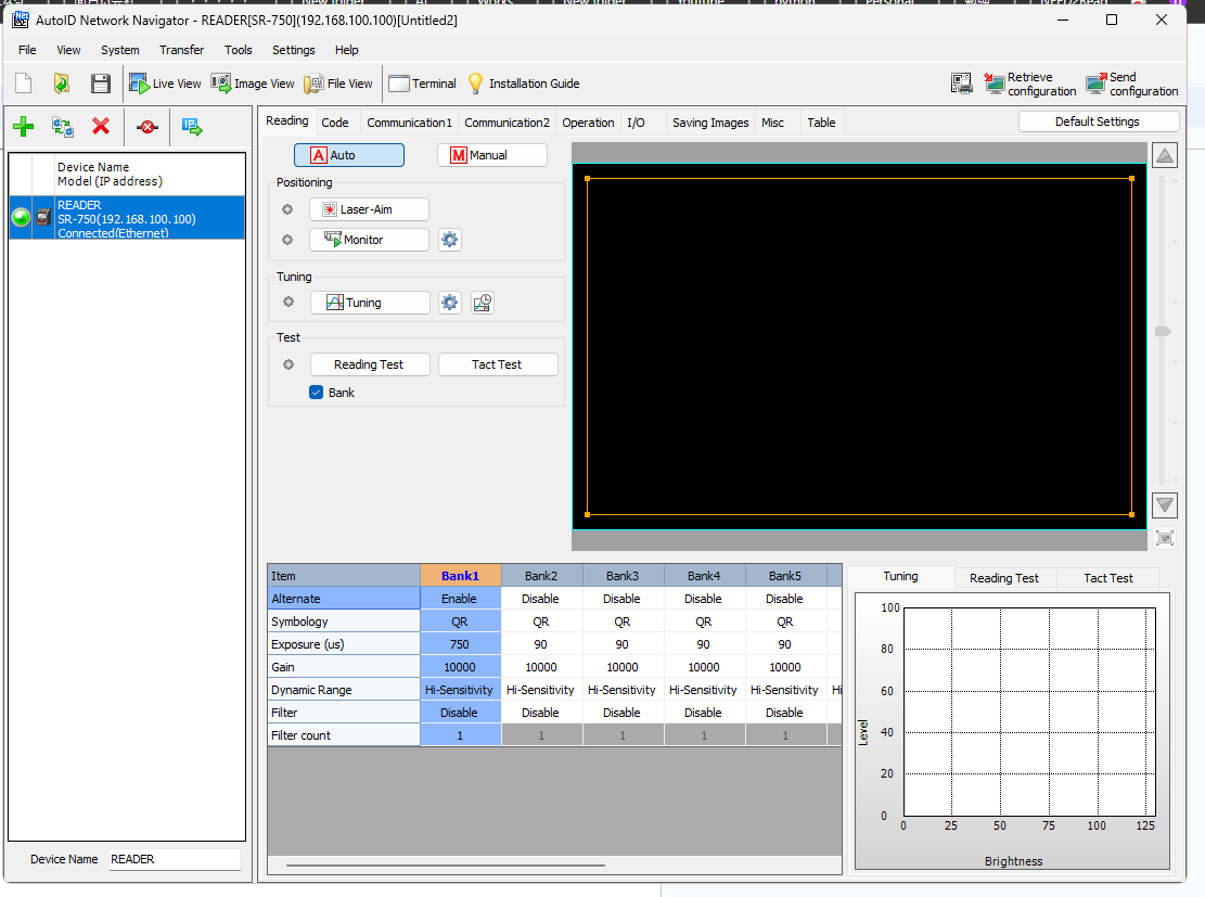
The device just registered in the device list has a green light, meaning it is currently connected to the PC and the SR-750.
Monitor
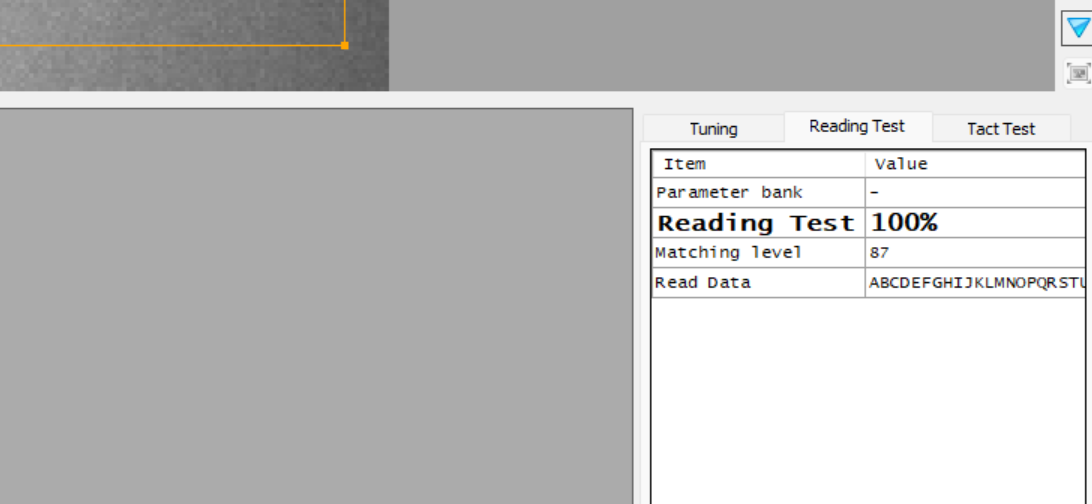
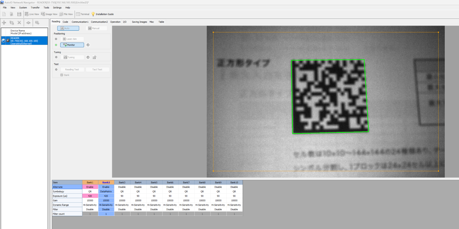
Click on the Monitor button to see a live image of the current camera.
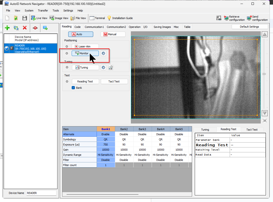
The camera can also recognize the 2D code well.
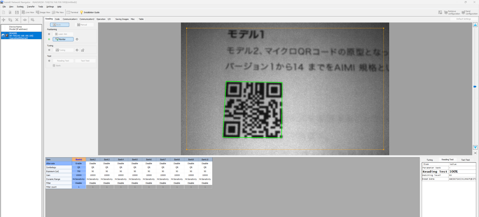
In the lower right corner, the Reading Test table provides 2D code data and test results.
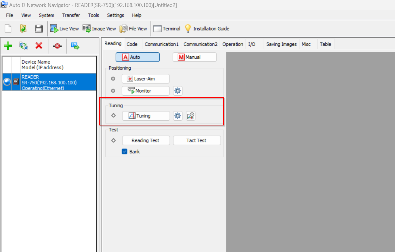
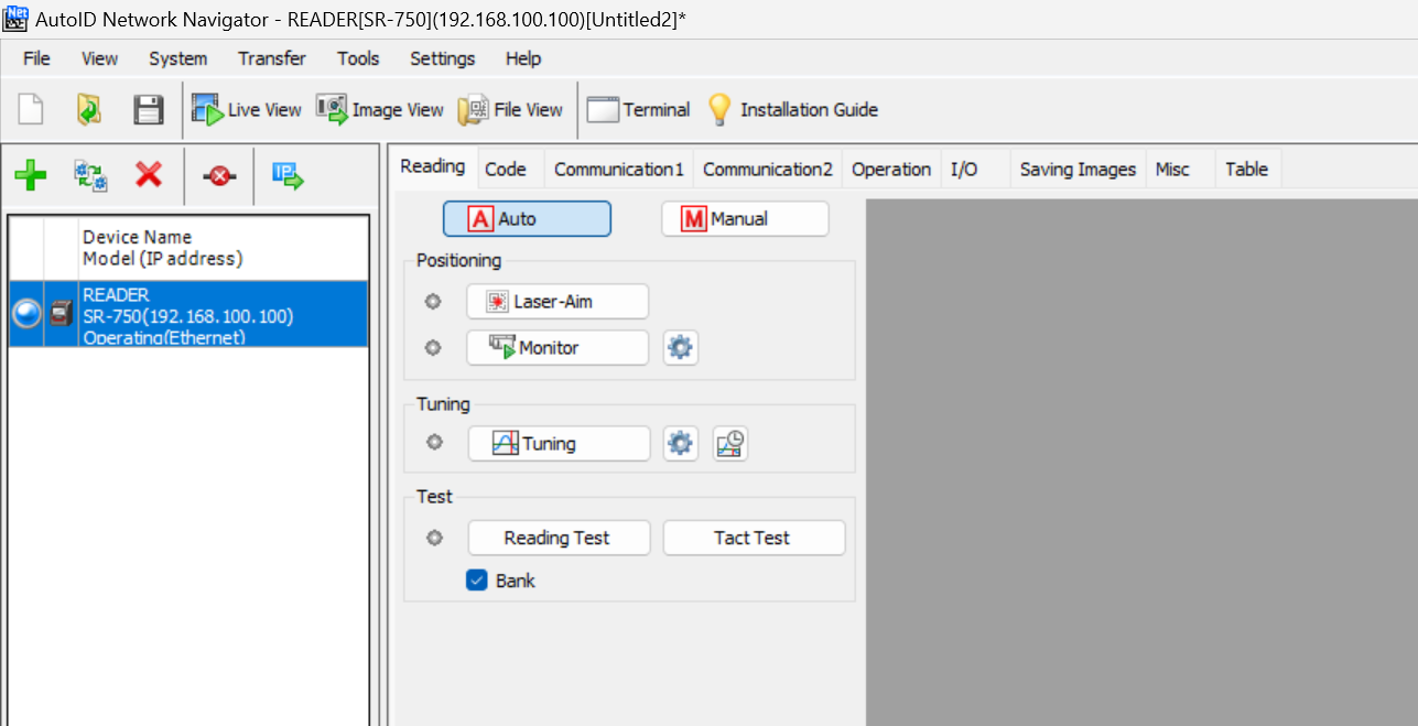
Tuning
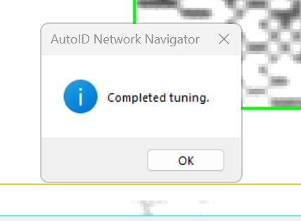
You can also click the Tuning button to automatically adjust the camera.
Done!
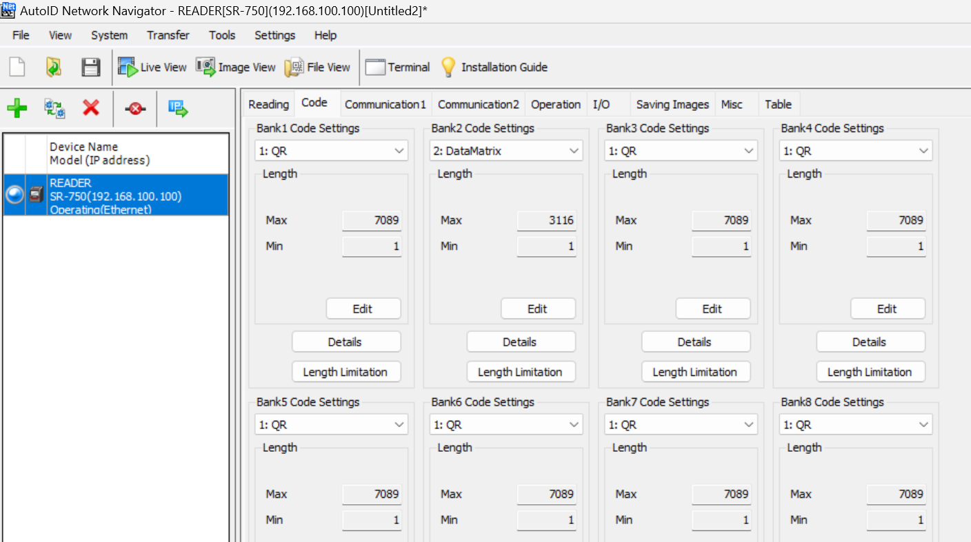
Code
Open Code to set the 2D code to read each bank.
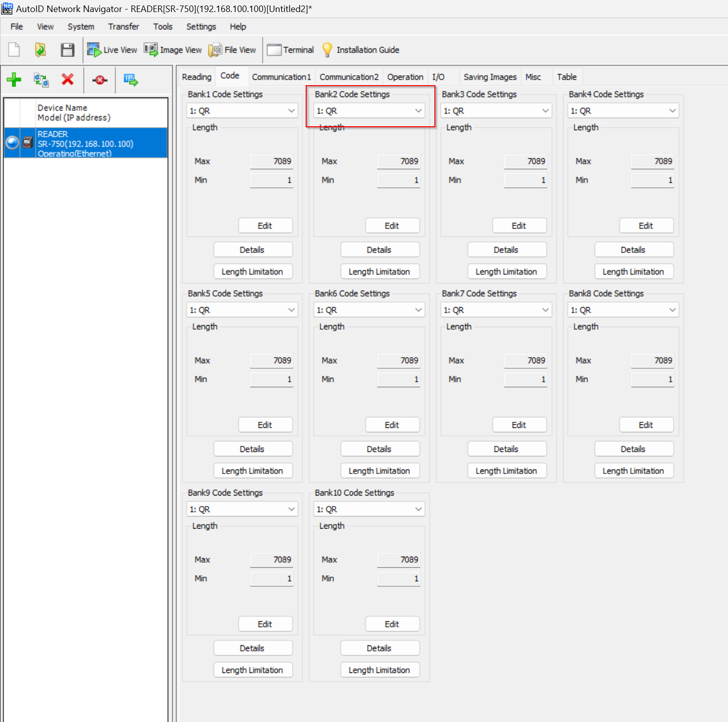
Set the Code from the Drop List.
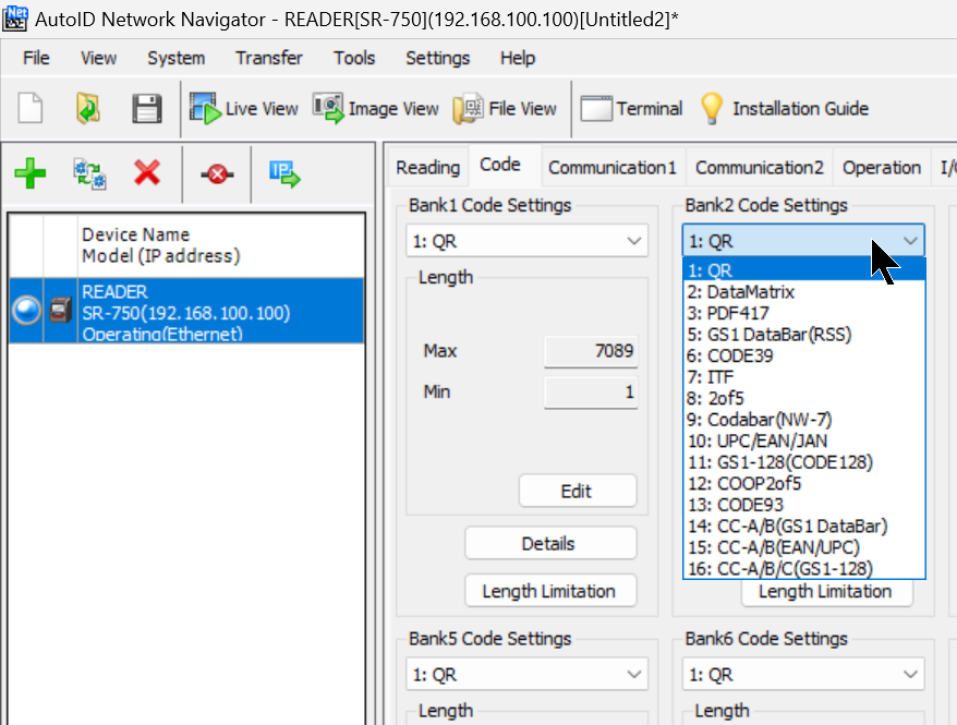
Done!
Return to Reading Tab.
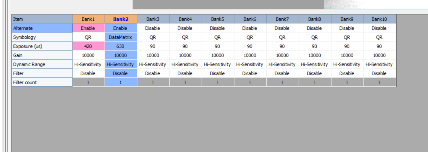
Below, you changed Bank2 to DataMatrix.
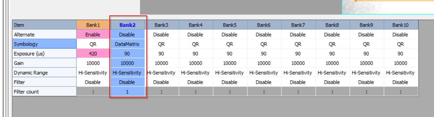
Result
Done!It was also detected in the DataMatrix code.
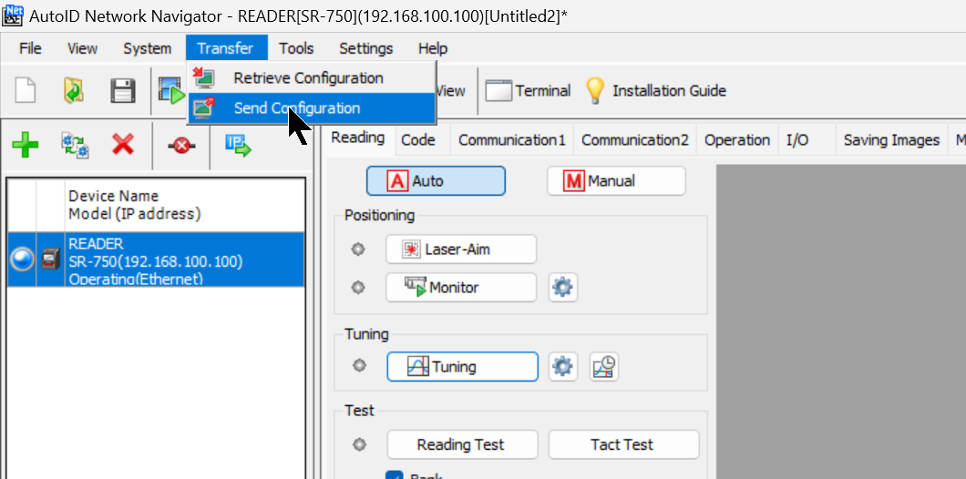
Send Configuration
Once you have completed the setup of the SR-750, use Transfer>Send Configuration to transfer your project to the device.
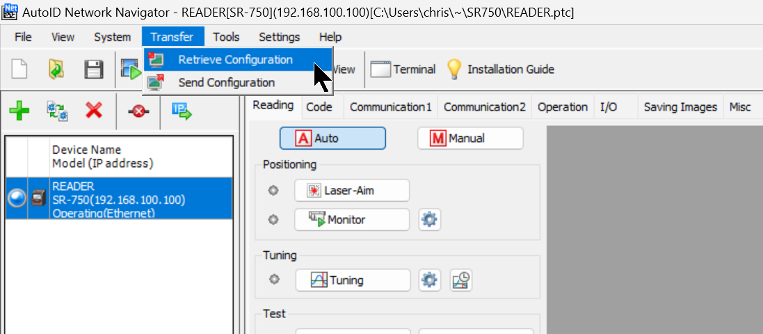
Retrieve Configuration
You can also upload the configuration by using ”Retrieve Configuration” Function.
Ethernet/Ip?
EtherNet/IP is an industrial communication network proposed by ODVA (Open DeviceNet Vendor Association Inc.
It is an industrial communication network proposed by ODVA (Open DeviceNet Vendor Association, Inc.),
EtherNet/IP communication can share a network with normal Ethernet communication.

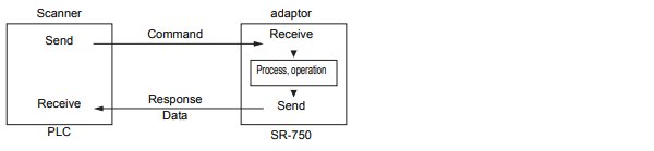
Scanner and adaptor
In EtherNet/IP communication, one device opens a communication line, called a “connection,” to another device.
The device that opens the connection is called the “scanner” (originator) and the receiving device is called the “adapter” (target); the PLC is used primarily as the scanner and the SR-750 is the adapter device.
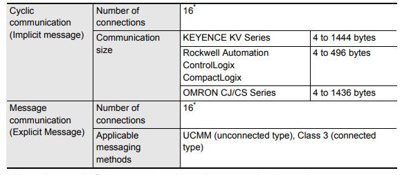
Cyclic communication and message communication
In EtherNet/IP, there are two types of communication: cyclic communication (Implicit message), in which cyclic data is sent and received, and message communication (Explicit message), in which command/response is sent and received.
(Explicit message).
Cyclic communication
Cyclic Communication Cyclic communication allows the RPI (communication cycle) to be set according to the priority of data to be sent and received. Data can be sent and received with the overall communication load adjusted.
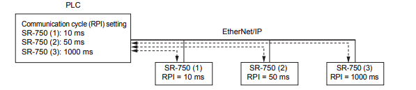
When using EtherNet/IP for cyclic communication with the SR-750 series, the SR-750 series functions are assigned to PLC devices.
Note that communication settings such as communication cycle and data size for cyclic communication are made on the PLC side. Also, in a network connecting many devices including EtherNet/IP devices, delays or packet loss may occur if the load is heavy. Please verify the settings thoroughly before operation.
Function Overview
Reading instruction
It also performs read instructions, as well as operations such as end-of-reading, bank setting reading, etc.
Preset instructions
Records normally read data as preset data. It also registers or deletes preset data from the PLC.
Calibration instructions
Calibration can be performed and calibration results can be stored in a set bank.
Error-handling
Checks for the cause of an error in the main unit and returns an error.
(For example: Buffer overflow check/cancellation)
Main unit status acquisition
Check the status of the main unit (BUSY status).
Operation results acquisition
When set to silent mode, readings are not updated.
Terminal status acquisition
Obtains the status of input and output terminals.
Main unit reset instructions
Displays the software reset for the SR-750 series.
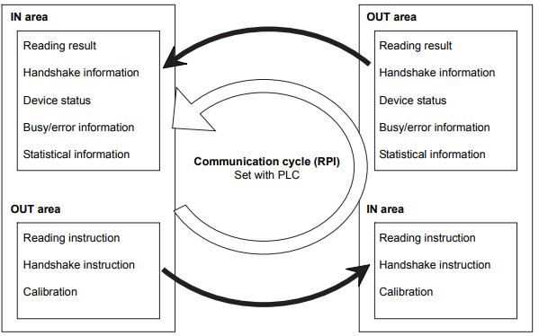
Assemblies
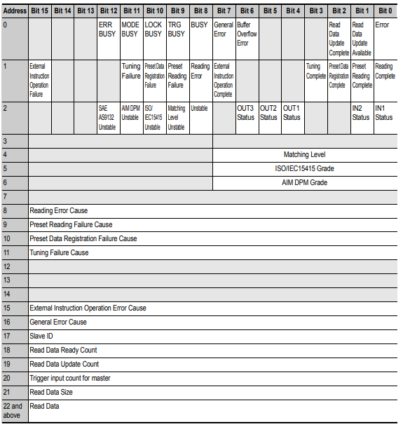
Result data (Input Assemblies)
The input assembly is a device that writes responses from the SR-750 series to the PLC.
(Instance ID: 0x64)
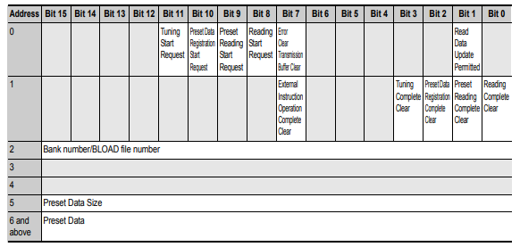
Control data (Output Assemblies)
The output assembly is a device that writes commands from the PLC to the SR-750 series.
(Instance ID: 0x65)
Message communication
In message communication, timing is controlled by command/response.
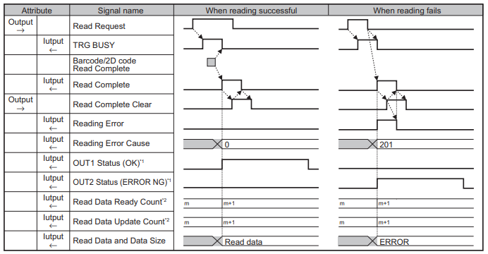
Specification Of SR-750
This is for SR-750 Ethernet/IP connection use.
Time chart
Implementation
Keyence Side
IPComm
Open the Tab of Communication1 and set the IP address and Subnet Mask of the SR-750.
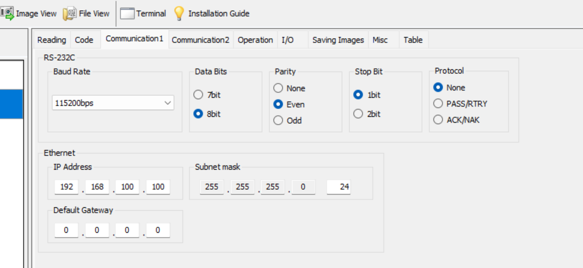
Comm
Next, open the Communication2 Tab and set Data Port2 to Ethernet.
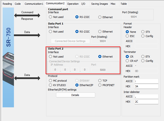
Protocol
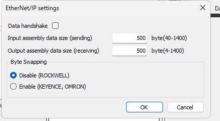
Then set Protocol to Ethernet/IP and click the Details button.
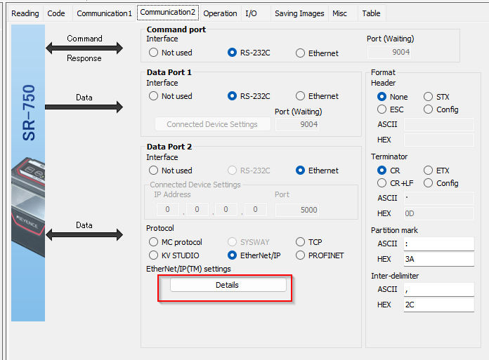
You can set the data size and Byte Swaping for Ethernet/IP connections, but leave it at Default this time.
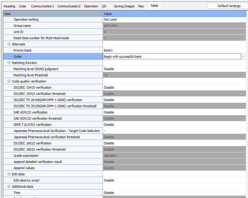
Table
Open the Table Tab to list and set SR750 parameters.
TwinCAT3 Side
Now set up the TwinCAT3 side.
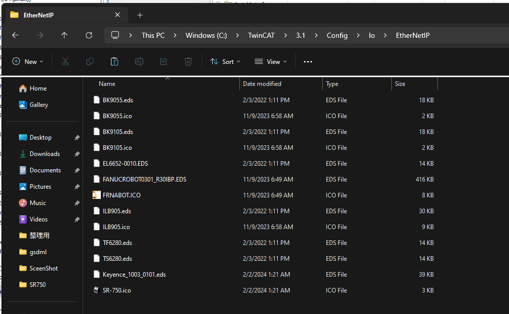
Install EDS File
Download the EDS File for SR-750 from Keyence HP and store it in the following Directory.
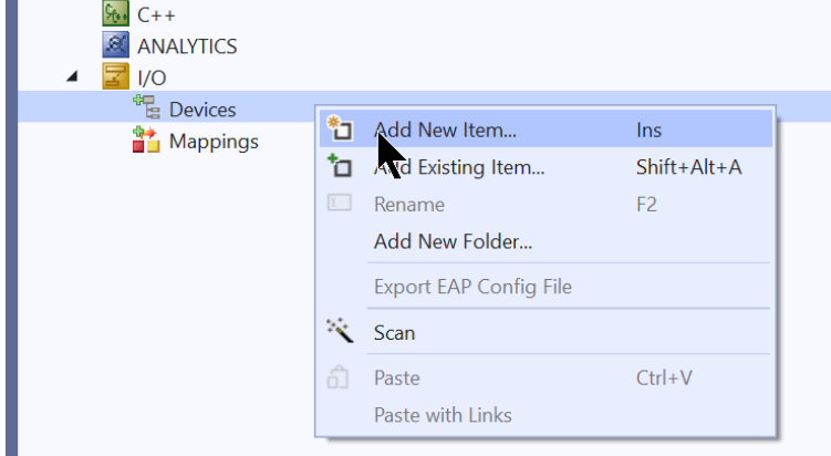
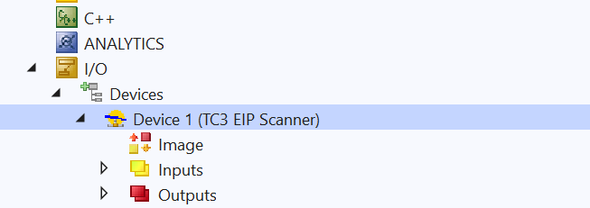
Add Devices
Add a new Fieldbus Driver under I/O>Devices>Add New Item.
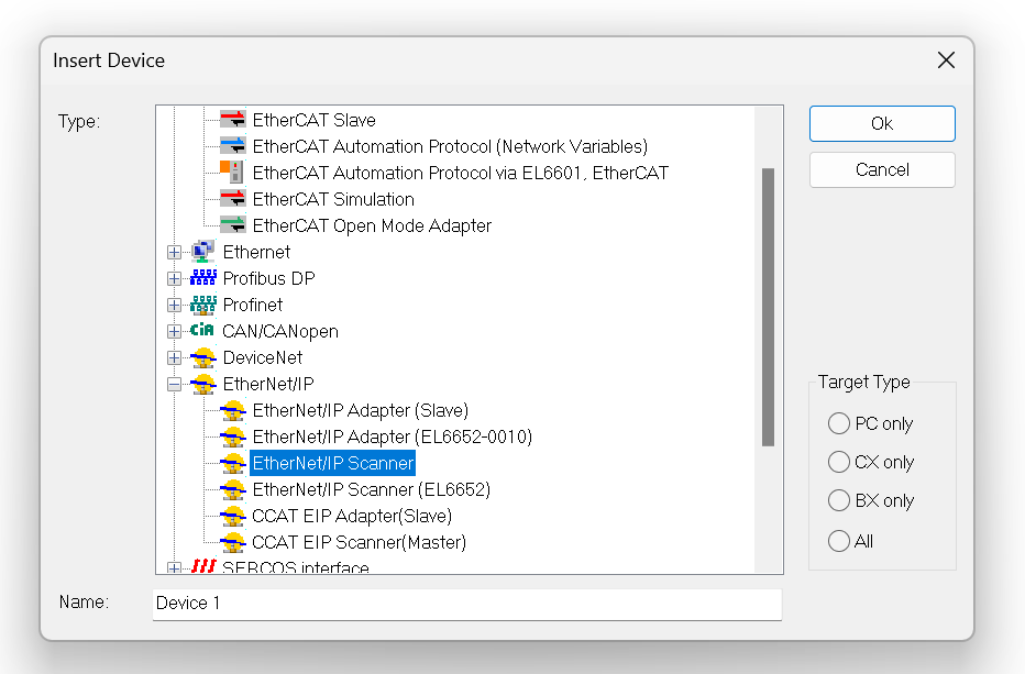
Select Etherent/IP>Ethernet/IP Scanner>Ok to proceed.
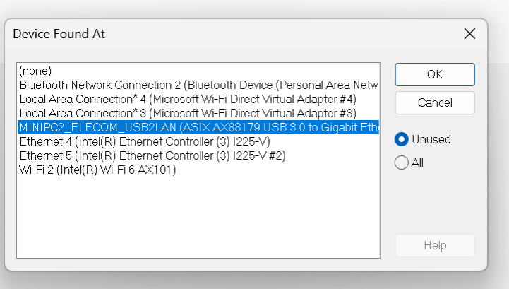
Open the Adapter’s Tab and click the Search button to set the Scanner Network Interface to be used as the Etherent/IP Scanner.
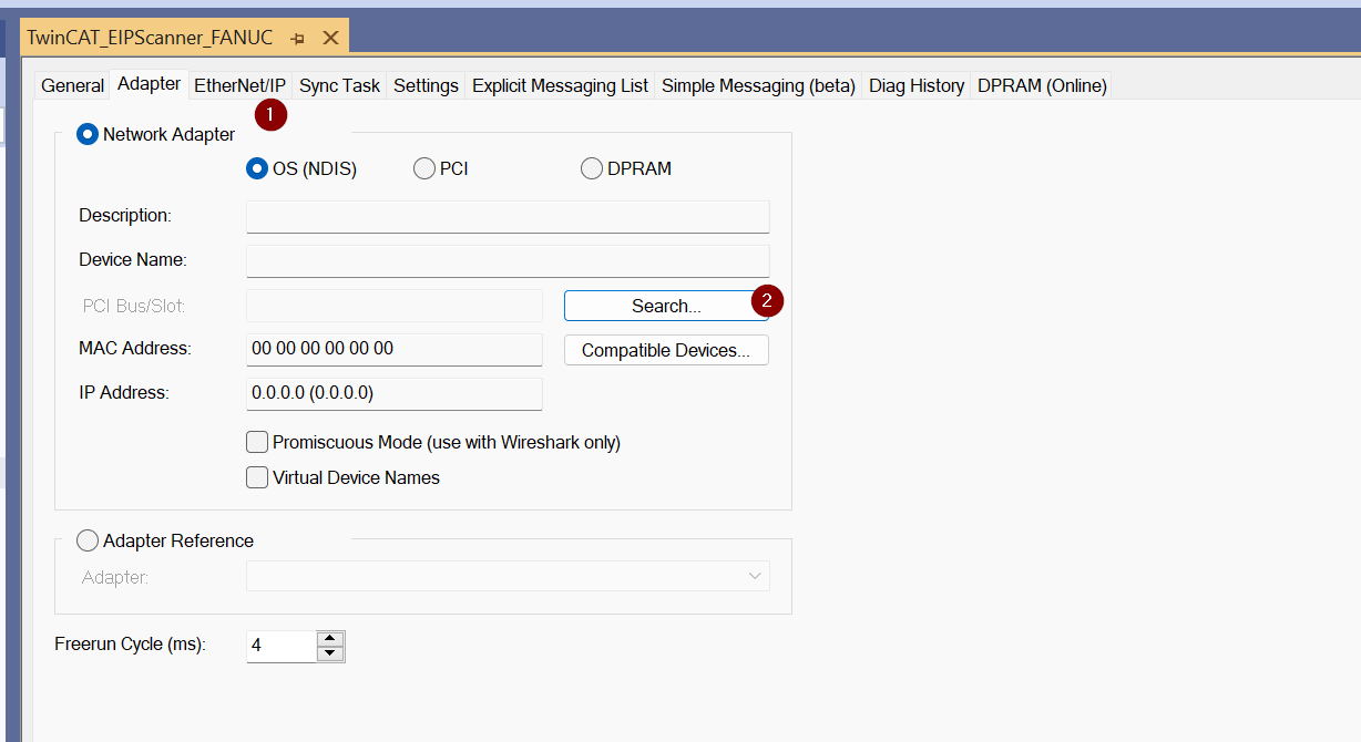
Lists the Network Interfaces currently available on IPC.
Task
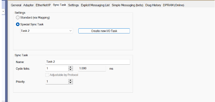
Next, open the Sync Task to add the Ethernet/IP Scanner Task.
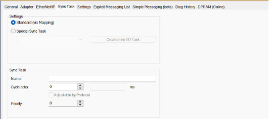
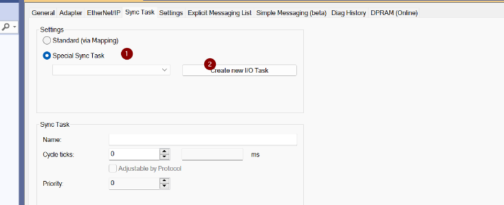
Select Special Sync Task > Create new I/O Task.
Enter a new Task name.
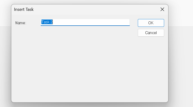
Done!
Scanner IP
Next, set the IP address of the Ethernet/IP Scanner. Click on the Ethernet/IP Scanner you just added.
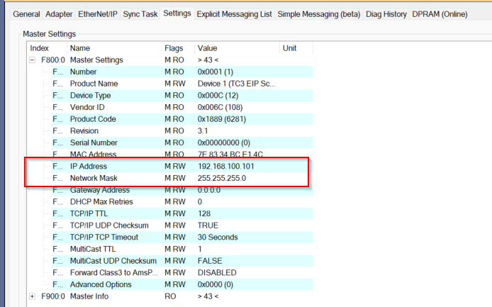
Open the Settings Tab.
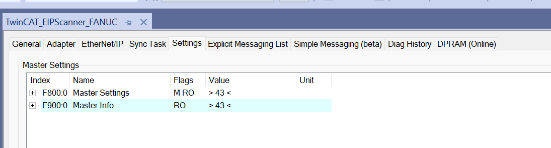
Set the IP address, Network Mask, and Gateway address in F800.0.
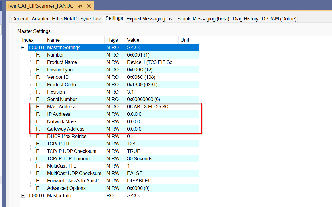
Done!
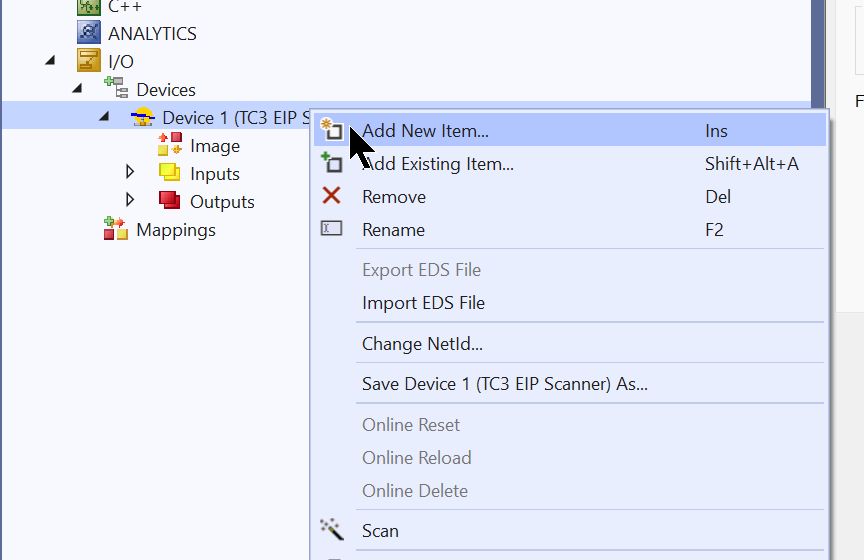
Add SR-750 Adapter
Now that the Ethernet/IP Scanner configuration is complete, the next step is to add Keyence’s Ethernet/IP Adapter SR-750. Right click on the Scanner you just configured and select Add New Item.
Select SR-750>Ok.
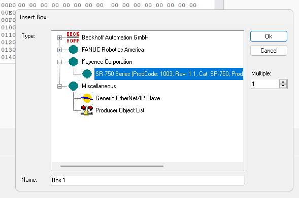
Done!
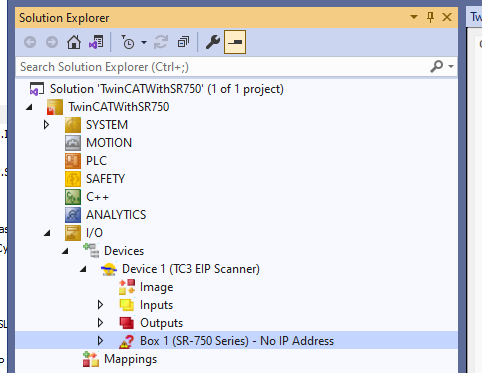
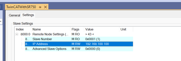
Adapter IP
Set the Ip address of the Keyence SR-750 from Settings>8000.0.
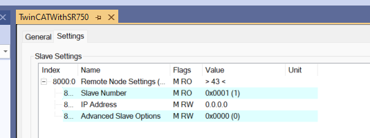
In this Tutorial, it will be 192.168.100.100.
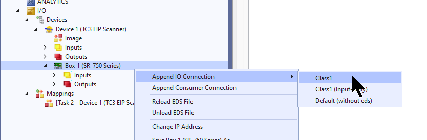
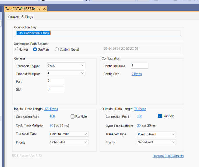
Add Connection
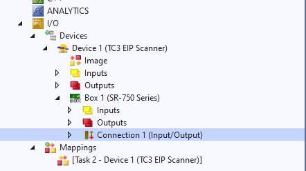
Now we can Configure Ethernet/IP Connection between Beckhoff TwinCAT3 and Keyence SR-750.Right click on the Keyence SR-750 Adapter you just added>Append IO Connection>Class1.
Do you want to automatically create variables along with the EDS File?
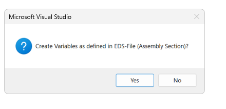
Done!Connection has been added.
Etherent/IP communication settings should be configured according to the actual application.
Add PLC
Now that we have finished setting up Fieldbus, the next step is to create a PLC program.
PLC>右クリック>Add New Itemします。
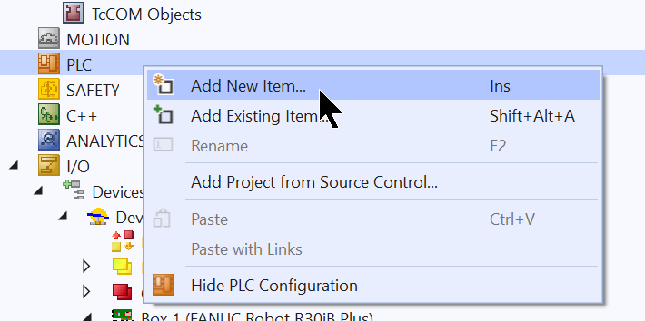
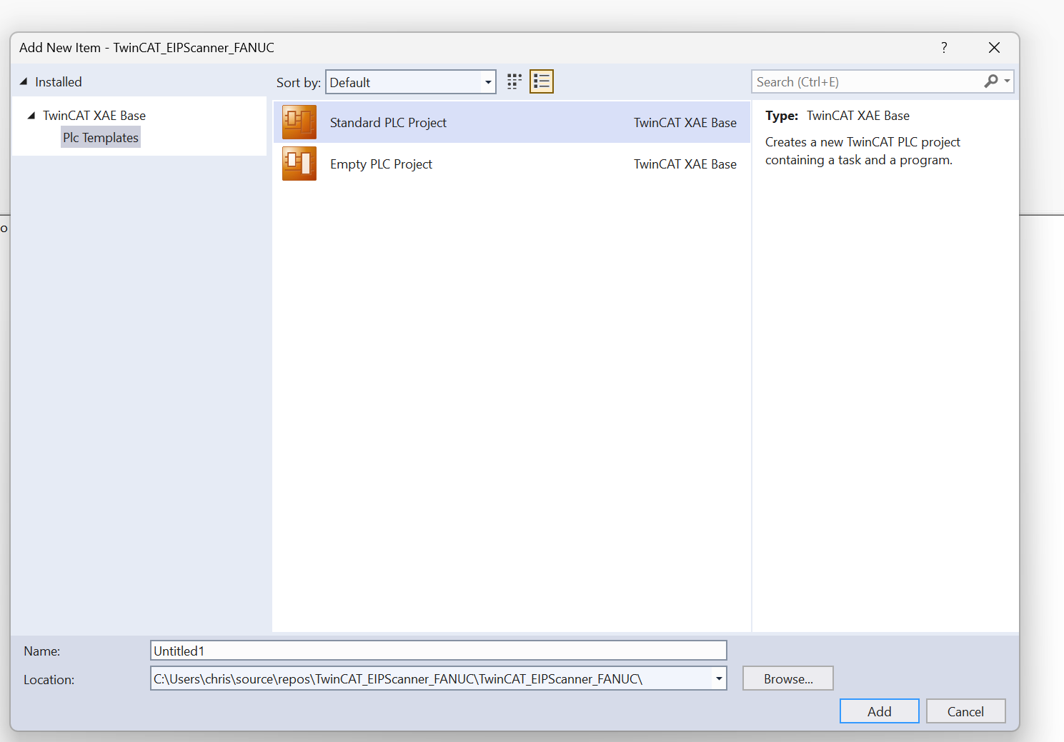
Select Standard PLC Project>Add.
DUT
DUT_SR750_EIP_INData
This is a structure defined for the Input Assembly of SR750 Ethernet/IP.
| TYPE DUT_SR750_EIP_INData : STRUCT Error :BIT; //Buffer Overflow Error OR General Error is ON. ResultDataAvailable:BIT; //This displays whether read data exists or not,using in Handshake ResultDataStrobe:BIT; // BufferOverFlow:BIT; //buffer overflow error occurs. GeneralError:BIT; Busy:BIT; //TryBusy,LockBusy,ModeBusy or ErrBusy is on TryBusy:BIT; LockBusy:BIT; ModeBusy:BIT; ErrBusy:BIT; ReadComplete:BIT; //when reading is complete PresentComplete:BIT; //when preset reading is complete. RegisterPresetDataComplete:BIT; //when preset data registration is complete. TuneComplete:BIT; //when tuning is complete. EXTRequestComplete:BIT; //when “Reading”, “Preset reading” or “Tuning” is performed with the IN terminal or command and the operation is complete. ReadFailure:BIT; //when reading error or comparison NG occurs. PresentFaliure:BIT; //when preset reading fails. RegisterPresetDataFailure:BIT; //when preset data registration fails. TuneFailure:BIT; //when tuning fails. EXTRequestFailure:BIT; //when “Reading”,”Preset reading” or “Tuning” is performed with the IN terminal or command and the operation fails. IN1Status:BIT; //This represents IN1 terminal status. IN2Status:BIT; //This represents IN2 terminalstatus. OUT1Status:BIT; //This represents OUT1 terminal status. OUT2Status:BIT; //This represents OUT2 terminal status. OUT3Status:BIT; //This represents OUT3 terminal status. noname5_arrBIT:BIT; Unstable:BIT; //ON when any of the following Unstable Bits (9 to 12) is ON. MatchingLevelUnstable:BIT; //Matching level judgment result ISOIEC15415Unstable:BIT; //ISO/IEC15415 verification judgment resul AIMDPMUnstable:BIT; //ISO/IEC TR 29158 (AIM DPM-1-2006) verification judgment result SAEAS9132Unstable:BIT; //SAE AS9132 Unstable verification judgment result MatchingLevel:UINT; ISOIEC15415Grade:UINT; AIMDPMGrade:UINT; ReadResultCode:UINT; PresentResultCode:UINT; RegisterPresetDataResultCode:UINT; TuneResultCode:uint; EXTRequestResultCode:UINT; GeneralErrorCode:UINT; ReadyDataReadyCount:UINT; ReadyDataUpdateCount:UINT; ResultDataSize:UINT; ResultData:ARRAY[0..127]OF BYTE; END_STRUCT END_TYPE |
DUT_SR750_EIP_OutData
This is a structure defined for the SR750 Ethernet/IP Output Assembly.
| TYPE DUT_SR750_EIP_OutData : STRUCT ResultDataLatch:BIT; ErrorClear:BIT; ReadRequest:BIT; //The SR-750 Series starts reading. PresetRequest:BIT; //Preset reading starts. RegisterPresetDataRequest:BIT; //Specified preset data is registered to Address 5, 6 and above TuneRequest:BIT; //Tuning starts ReadCompleteClear:BIT; //”Reading Complete” Bit of Input Assemblies is cleared. PresetCompleteClear:BIT; //”Preset Reading Complete” Bit of Input Assemblies is cleared. RegisterPresetDataCompleteClear:BIT;//”Preset Data Registration Complete” Bit of Input Assemblies is cleared. TuneCompleteClear:BIT; //”Tuning Complete” Bit of Input Assemblies is cleared. EXTRequestCompleteClear:BIT; //”External Instruction Operation Complete” Bit of Input Assemblies is cleared. BankNumber:UINT; //Input a bank number here and start reading. UserDataSize:UINT; UserData:array[0..63]OF BYTE; END_STRUCT END_TYPE |
DUT_SR750_EIP
This is the structure that summarizes the Input Assembly and Output Assembly that we just mentioned.
| TYPE DUT_SR750_EIP : STRUCT in AT %I*:DUT_SR750_EIP_INData; out AT %Q*:DUT_SR750_EIP_OutData; CommStatus AT %I*:UINT; END_STRUCT END_TYPE |
DUT_HMI_SR750_PB
This is the structure that operates the SR750 from the HMI.
| TYPE DUT_HMI_SR750_PB : STRUCT bRead:BOOL; bClear:BOOL; bReset:BOOL; END_STRUCT END_TYPE |
DUT_HMI_SR750_PL
This is a structure that displays the status of SR750 on the HMI.
| TYPE DUT_HMI_SR750_PL : STRUCT Status:DUT_SR750_EIP_INData; Data:STRING; END_STRUCT END_TYPE |
DUT_HMI_SR750
This is the structure that summarizes the operation and display of the HMI.
| TYPE DUT_HMI_SR750 : STRUCT PB:DUT_HMI_SR750_PB; PL:DUT_HMI_SR750_PL; END_STRUCT END_TYPE |
GVL
GVL_HMI
This is the Global variable for HMI operation.
| {attribute ‘qualified_only’} VAR_GLOBAL SR750_1:DUT_HMI_SR750; END_VAR |
GVL_Mapping
This is the Global variable for Mapping Ethernet/IP data for SR750.
| {attribute ‘qualified_only’} VAR_GLOBAL SR750_1:DUT_SR750_EIP; END_VAR |
Program
This program triggers the SR750 via Ethernet/IP, acquires its status and displays it on the HMI.
| PROGRAM MAIN VAR Result:STRING; bRead:BOOL; R_TRIG:R_TRIG; END_VAR GVL_Mapping.SR750_1.out.ReadRequest:=GVL_HMI.SR750_1.PB.bRead AND GVL_Mapping.SR750_1.CommStatus=0 ; R_TRIG(CLK:=GVL_Mapping.SR750_1.out.ReadRequest); IF R_TRIG.Q THEN Result:=’ ‘; END_IF IF GVL_Mapping.SR750_1.in.ReadComplete THEN MEMMOVE( destAddr:=ADR(Result) ,srcAddr:=ADR(GVL_Mapping.SR750_1.in.ResultData) ,n:=GVL_Mapping.SR750_1.in.ResultDataSize); ELSIF GVL_Mapping.SR750_1.in.ReadFailure THEN GVL_HMI.SR750_1.PL.Status.ResultDataSize:=0; GVL_HMI.SR750_1.PL.Data:=’ERROR!!!!’; END_IF; GVL_Mapping.SR750_1.out.ErrorClear:=GVL_HMI.SR750_1.PB.bReset; GVL_Mapping.SR750_1.out.ReadCompleteClear:=GVL_HMI.SR750_1.PB.bClear; GVL_HMI.SR750_1.PL.Status:=GVL_Mapping.SR750_1.in; GVL_HMI.SR750_1.PL.Data:=Result; |
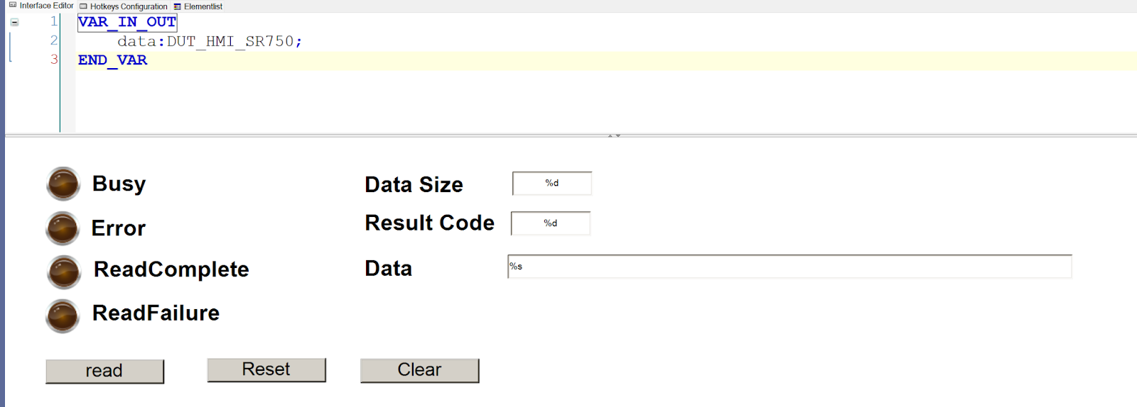
Visualize
This is the SR750 operation screen.
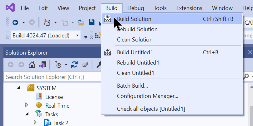
Build
Compile the project under Build>Build Solution.
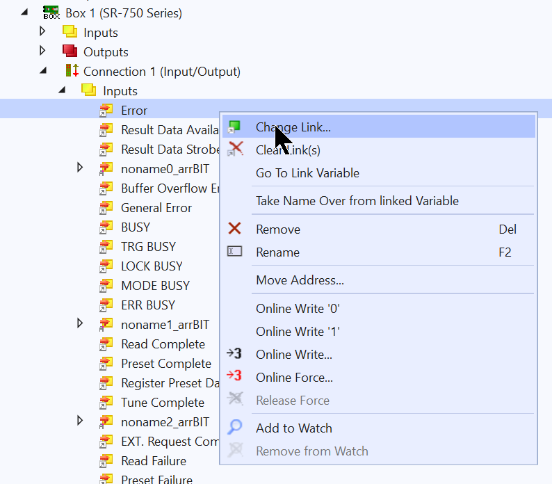
Link Input/Output
Mapping the SR750’s input/output Process Data to the PLC.
Download
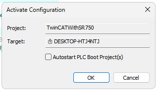
The last step is to Download the project to Runtime in Activate Configuration.
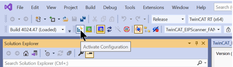
OK to proceed.
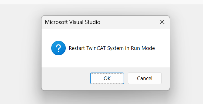
Switch TwinCAT to Run Mode.
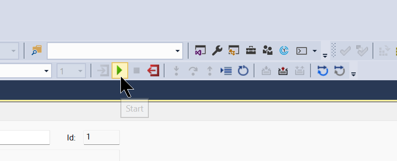
Start
Finally, start TwinCAT3 Runtime.
Result
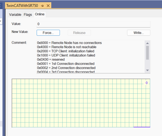
Open State to check the Ethernet/IP connection status between SR750 and TwinCAT3.
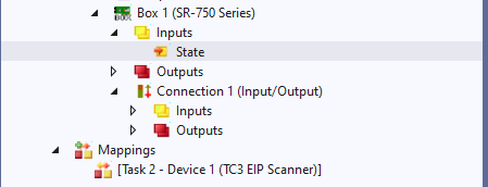
State=0, so now TwinCAT3 and Ethernet/IP are connected properly.
Here is a video of a Trigger being sent from TwinCAT3 to SR750 to read a QR Code.
Beckhoff.Using Ethere/IP to communicate with Keyence SR-750(QR Code)
Here is a movie of sending a Trigger from TwinCAT3 to SR750 and reading Data Matrix.
Beckhoff.Using Ethere/IP to communicate with Keyence SR-750(DataMatrix)
Project Download
Download the project for this article at this Link.
https://github.com/soup01Threes/TwinCAT3/blob/main/TwinCATWithSR750_EIP.tnzip