This article is a series explaining how to build from scratch when creating a safety program from Beckhoff’s TwinSAFE. Let’s start!
Thanks!
Because of Beckhoff Japan that lent the devices to me – I can create this post.
Beckhoff Japan
IPC6920-005 and the safety Terminal were lent by Beckhoff Japan, a Japanese subsidiary of Beckhoff. Founded in 1980, Beckhoff Automation is a German company at the forefront of the introduction of open automation systems based on PC-based control technology.
Beckhoff Japan Corporation Beckhoff Automation Co., Ltd. established its head office in Yokohama in 2011 and the Nagoya office in 2017.

Here is the Home page of Beckhoff Japan.
https://www.beckhoff.com/ja-jp/
TwinSAFE project design
TwinSAFE allows manufacturers to build safety systems from a wide range of scales.
We offer everything from Stand-alone to distributed control and software control. Here’s a quick introduction to those outlets.
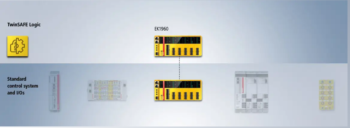
TwinSAFE as a stand-alone controller
By operating EK1960 and EP1957, you can implement a compact safety application from TwinSAFE. These devices are in Stand-alone mode, no EtherCAT communication, only Safe Local I/O. Of course, the Stand-alone component can also be 100% integrated as part of the overall system.
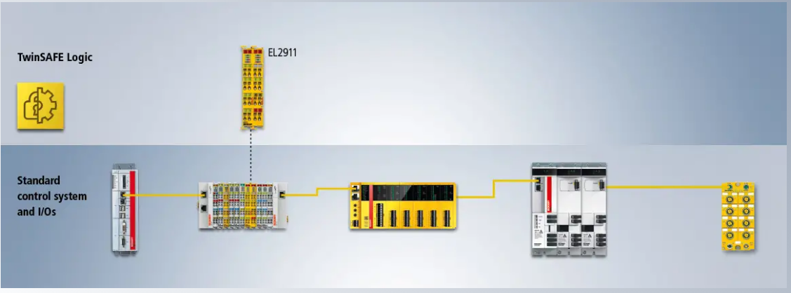
TwinSAFE as a compact controller
Incorporating the TwinSAFE Logic into the new TwinSAFE components and TwinSAFE I/O components expands the scope of where TwinSAFE can operate.
Local Input/Output Some components like EL1957 (e.g. EtherCAT Box, 8-channel digital input + 4-channel digital output, 24 V DC, 0.5 A, M12, TwinSAFE, TwinSAFE Logic) communicate with other TwinSAFE Logic components can. (EL2911, EtherCAT Terminal, 4-channel digital input + 1-channel digital output, 24 V DC, 10 A, TwinSAFE, TwinSAFE Logic in this example)
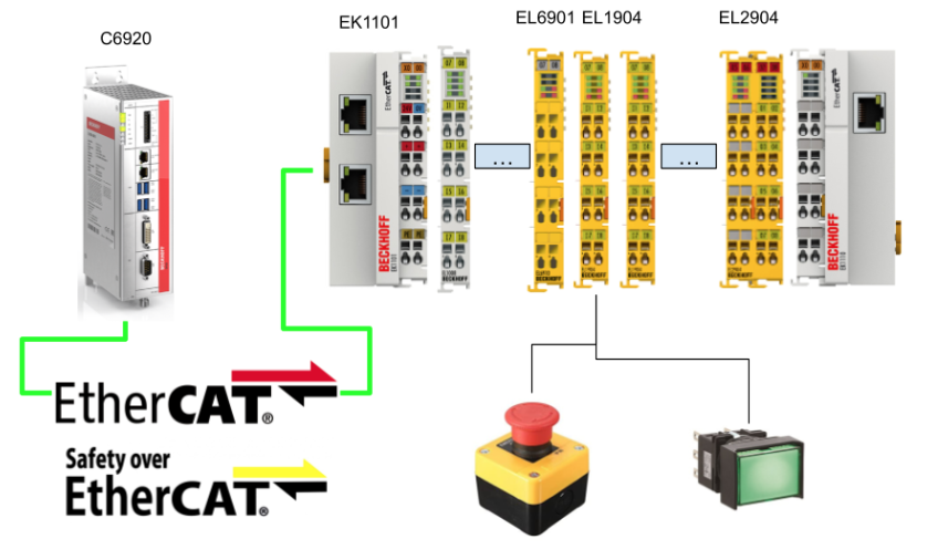
TwinSAFE as a central safety controller
TwinSAFE can also act as a Safety Controller in your application. For example, in the EL6910 introduced this time, instead of the module itself not having local Input and Output, it is possible to have a safety communication relationship with other Safety components and use those signals in the User Safety Program. You can communicate with other safety components just by sandwiching the TwinSAFE module in the standard IO as shown in the configuration below.,
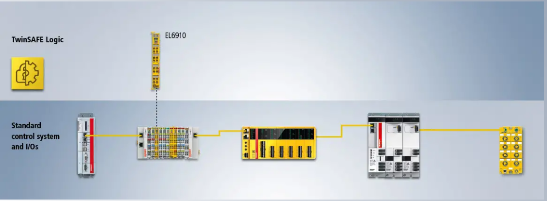
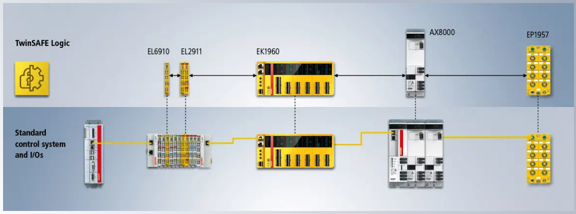
TwinSAFE as a distributed system
TwinSAFE can also be built as part of a distributed system for larger applications.
Compared to conventional systems, all non-safety related inputs and outputs do not have to be transferred to the Safety Controller, and separate Safety Projects are created for the necessary safety components according to application functions. For example, as shown in the figure below, multiple modules are hanging in the AX8000 Group, and there are multiple Safety-related functions. Conventionally, all those module signals are taken into the EL6190, but thanks to TwinSAFE, only the EL6910 and EL2911 can communicate, and the EL2911 can control the AX8000 Group as a receiver.
Safety control with the standard Industrial PC
Finally, TwinCAT also offers Safety PLC Software, which allows the creation of Safety applications from standard IPCs. Unlike conventional TwinSAFE hardware, the Safety Controller uses Safety C, a language derived from standard C. This means you can build more complex safety applications.

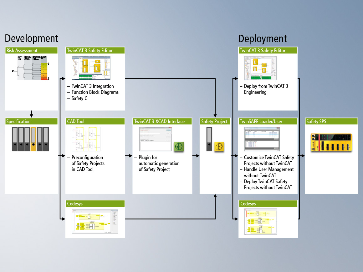
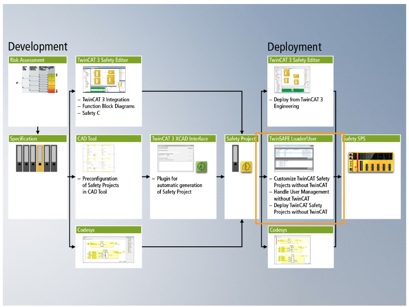
WorkFlow
Here is the Workflow of the TwinSAFE.
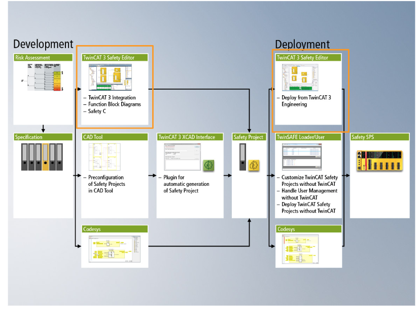
TwinCAT 3 and TwinCAT 2
By using Beckhoff, safety applications can be implemented with either TwinCAT2 or TwinCAT3. For TwinCAT2, only TwinCATSAFE Logic components of EL900, EL9630, KL6904 can be used, and for TwinCAT3, all except KL6904 can be used.
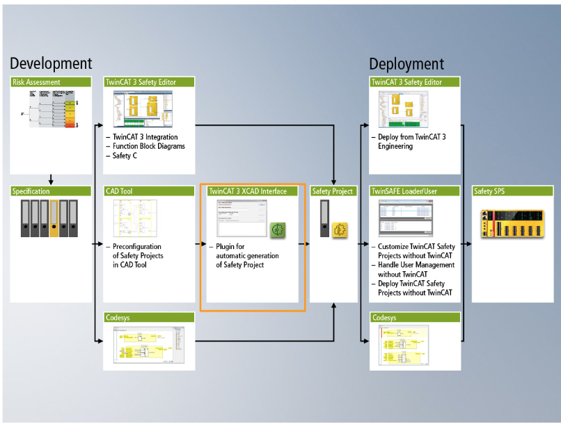
TwinCAT 3 XCAD Interface
Beckoff provides CAD tools to directly create safety applications. Finally the application is converted into a TwinCAT3 project and the Configuration via the TwinCAT3 XCAD Interface.
Codesys
We can also configure the Beckhoff TwinSAFE Logic components by using Codesys Safety.

TwinSAFE Loader
The TwinSAFE Loader Tool is a command line tool that allows you to download Safety projects without using the TwinCAT IDE. And TwinSAFE Loaders can be customized by the customer according to their own usage, but it is necessary to consider the risk.
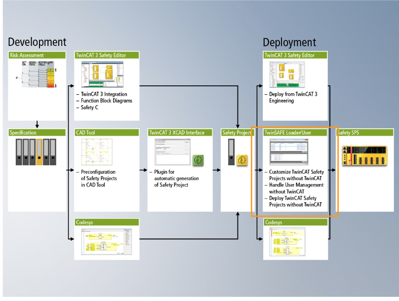
TwinSAFE User
The TwinSAFE User Tool is a user management role for TwinSAFE Logic components. (e.g. accessing components without going through TwinCAT IDE)
TwinSAFE reaction times
システムにあるTwinSAFE TerminalではSafety-over-EtherCAT Protocol使用しSafetyデータを交換します。これから実際にSensorからActuatorまでの流れを見ていきましょう。
Typical reaction time
The typical Reaction time is meant- Get the input data > Execute Logic in TwinCAT >Output the Actuator without any error.
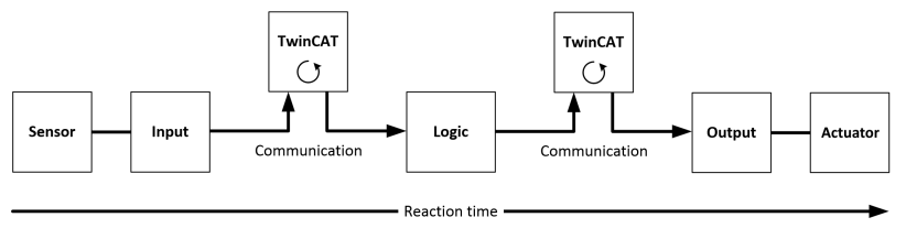
RT-Sensor
RT-Sensor is the time until the sensor signal flows to the Interface. The sensor response time is basically in line with the sensor manufacturer’s standards.
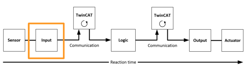
RT-Input
RT-Input is the response time of the safety input, e.g. EL1904 or EL1908. Its response time can be found from the Data-sheet. (For example, EL1904 is 4ms.)
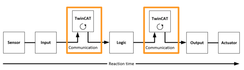
RT-Communication
The communication response time takes about three times the EtherCAT cycle time because the data is sent via Safety-over-EtherCAT Telegram. The time depends on the PLC or NC.
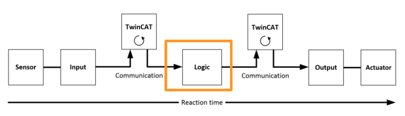
RT-Logic
Logic Terminal’s response time is the Logic Terminal’s own Cycle Time, which for the EL6900 is typically 500 µs to 10 ms. Actual Cycle time also depends on Safety Project size.
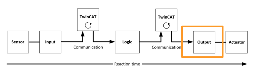
RT-Output
Here is the output Terminal response time. The Standard is about 2-3ms.
RT-Actuator
The Actuator response time and it depends on the manufacturer.
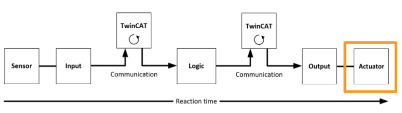
Formula
Typical total response time is:
| RT=RT-Sensor+RT-Input+3*RT-Communication+RT-Logic+RT+3*Communication+RT-Output+RT-Actuator |
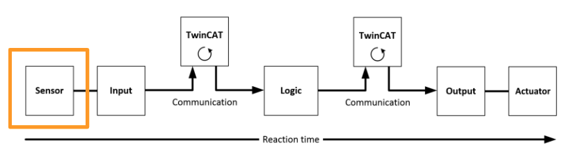
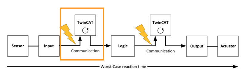
Worst-case reaction time
Case1
Let’s assume that a communication error occurred when transferring the signal from Sensor to the Input Terminal and from that Input signal to the Communication Interface of TwinCAT.
The communication error is detected by the Watchdog Time setting.
Case2
The Input signal was successfully delivered from the Sensor to the Input Terminal, and from the Input Terminal to the TwinCAT System to the Communication Interface.
This time, a communication error from the EL6900 to the communication interface between TwinCAT was detected by the Watchdog Time setting, and the output was shut down.
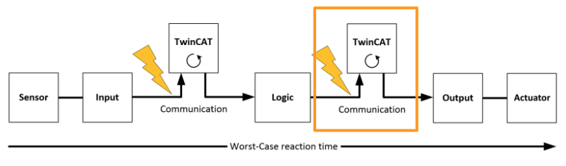
Formula
So the worst response time is;
| RT=Watchdog(Communication)+Watchdog(Communication)+RT-Actuator |
Summary
As a final summary, the TwinSAFE components provided by Beckhoff can use the same Fieldbus cable for safety and standard signals, and TwinSAFE Telegram will be integrated
into the standard Controller. There are also advantages in terms of maintenance, such as easy component replacement and diagnostic information history.
TwinSAFE has the following basic Safety components:
- Safety Input(e.g. EL19xx,EP1908)
- Safety Output(e.g. EL29xx)
- Drive Components(e.g. 例えばAX5805)
- Logic Components (e.g. EL6900,EL6910)
We can imagine that Sensor input of Safety and safety output of Actuator are wired to EL19xx and EL29xx, and logic processing is entrusted to EL69xx.
Safety over EtherCAT protocol(FSoE)
- Send and receive safety data using black channel
- TwinSAFE Communication can be used with EtherCAT・Lightbus・Profibus・PROFUBET・Ethernet
- IEC 61508:2010 EIL 3
- FSoE is IEC61784-3-12 and ETG standard (ETG.5100)
Fail-safe (Fail stop)
The basic rule of the safety system is to never miss a dangerous situation, and always switch off the power in a dangerous situation.
EL6910 | EtherCAT Terminal communication interface, TwinSAFE Logic
Multiple safety applications can be implemented because the EL6910 can also process analog values compared to the EL6900’s Boolean data processing only. Up to 212 connections are possible, and not only FSoe but also PROFISafe Master/Slave are supported.
Thanks to TwinSAFE SCRIPT Technology, standard Ethernet I/O (identifier -009x) can also exchange safety data to TwinSAFE Logic components.
The new EL6910 also has its own Checksum in the four components Logic, parameters, mapping, and info data. So, if there is a change in the Safety Project, it will be possible to calculate the Checksum more easily and efficiently.
Besides that, the EL6910 can also store a history of diagnostic information on the device itself. All errors can now be read directly on the device.
The EL6910 can also be programmed on the TwinCAT3 Safety Editor.
feature
- Can process analog data
- Historical review of diagnostic information directly on the device
- Up to 212 safety connections
- Up to 128 TwinSAFE Groups
- Up to 40 Users
- PROFIsafe master ・slave support
- TwinSAFE SC support
Protocol
- TwinSAFE/Safety over EtherCAT
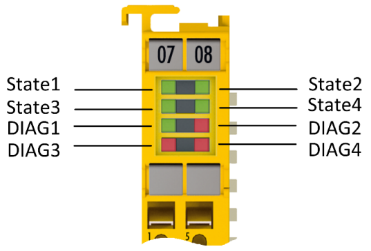
Layout
Here is the Layout of EL6910.
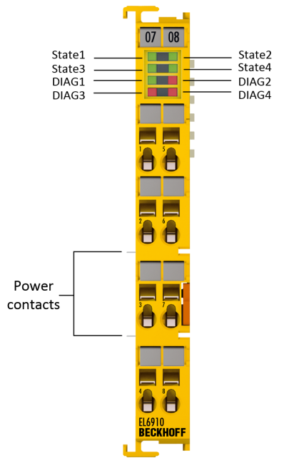
LED
| On | Flashing | OFF | |
| Diag1 (Green) | Environment and voltage, internal tests are also normal. | Environmental, voltage and internal tests are also out of range. | |
| Diag2(Red) | Turn on Dig3 and Dig4 at the same time. The module does Global Shutdown | Logic or environmental issues | Turns on simultaneously with Diag3 and Dig4. With Global Fault。 |
| Diag3(Red) | uC1 Global Shutdown・Global Fault | No uC2 Global Shutdown・Global Fault | |
| Diag4 (Red) | uC2 Global Shutdown・Global Fault | No uC1 Global Shutdown・Global Fault |
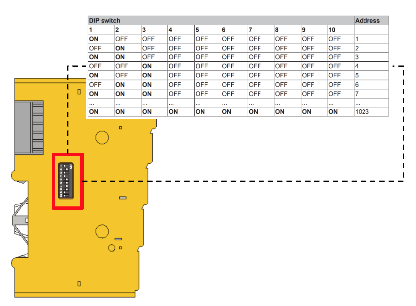
Address settings on TwinSAFE terminals
The TwinSAFE address can be set from 1-1023 using a 10-way DIP switch on the surface of the Safety Terminal. (Note that address duplication is prohibited and 0 is invalid)
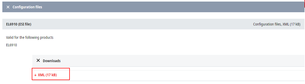
Update your device
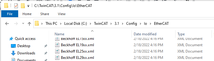
Just in case, download the EL6910 EDS File from the link below and update it.
https://www.beckhoff.com/en-en/products/automation/twinsafe/twinsafe-hardware/el6910.html
\TwinCAT\3.1\Config\io\EtherCATに貼り付けます。

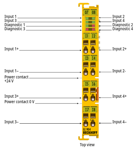
EL1904 | EtherCAT Terminal, 4-channel digital input, 24 V DC, TwinSAFE
It is this TwinSAFE 24V digital input Terminal EL1904 that is used with the EL6910 in this article to capture the safety input. The EL1904 has 4 Fail-safe inputs that can route signals via FSoE to TwinSAFE Logic components (EL6910).
Of course, the EL1904 also features 1:1 and 1:2 input evaluation and channel testing.
It should be noted that EL1904 also does not store the Safety parameter in the component itself, but instead transfers it via the TwinSAFE Logic component. Because of that mechanism, terminal replacement is easy, and safety parameters will automatically transfer parameters again when the safety application is restarted.
Special features:
- 4 Safety Input Chanel
- cross-circuit detection
- 1-channel and 2-channel evaluation
- Individual test settings for each channel

Layout
Implementation
Configuration
This is the configuration in this Tutorial. EL6901 is a Safety Logic Controller, and EL1904 has 2 channels connected to ESTOP and 1 channel connected to the Reset button.
Scan Devices
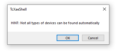
Using the Scan function to scan the network inside your ethercat network.Go to I/O > Devices>Right Click>Scan.

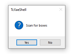
Please be careful that Not all types of devices can be scanned,Press Ok to continue.
Choose your Ethernet network interface>press OK to scan it.
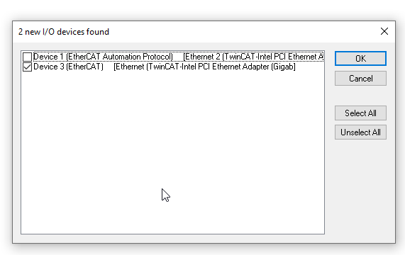
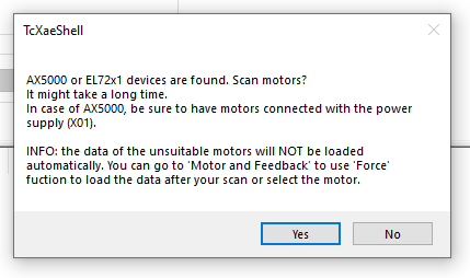
Yes.
Because the motor terminal is not used in this tutorial, we will choose “No”.
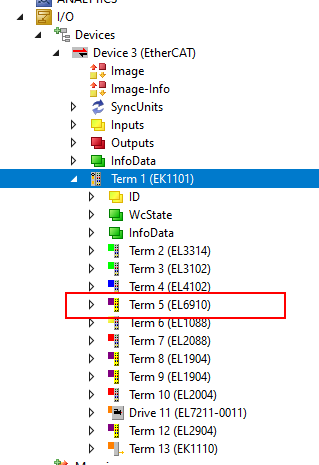
EL6910 is scanned and inserted in your project,Done!
Add PLC
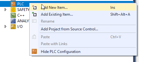
Select PLC>Right Click >Add New Item.
Select Standard PLC Project>Add it.

Add Safety Project
Go to SAFETY>Right Click>Add New Item.
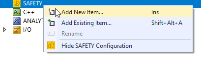
Choose TwinCAT Safety Project Preconfigured EndAck>Add.

EL6910 is used in my tutorial, choose “Hardware Safety PLC” as the Target and OK.

Safety Project is inserted.
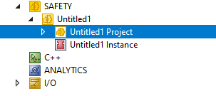
We can create the safety program in the TwinSAFEGroup.

Set Target System
Firstly,we need to configure the Target System in our Safety Project – Click the Target System.
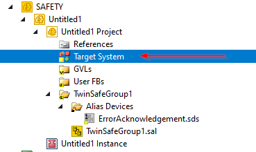
A Target configuration is shown.

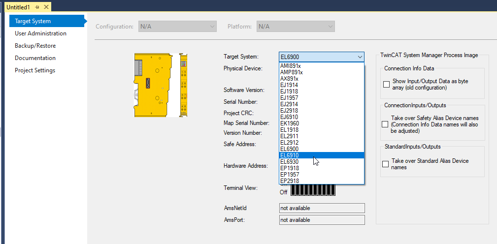
Select Target System
EL6900 is configured as your Target System in Default. we can click the Drop-down list to change it.
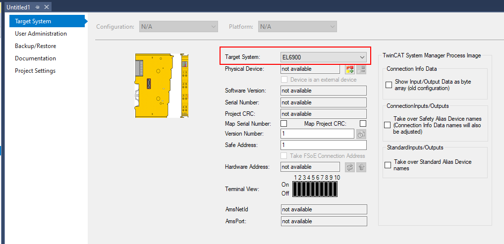
Select EL6910 as your target.
Set Physical Devices
Now we can link the Target System between your Safety Project and the real devices.
Click the button that is pointed with a red rectangle.

Please check if your Device is powered on or not/ the product code is correct or not , if you can not find the target device in this screen,or you can refresh it.
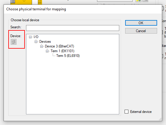
Coose EL6910>OK.

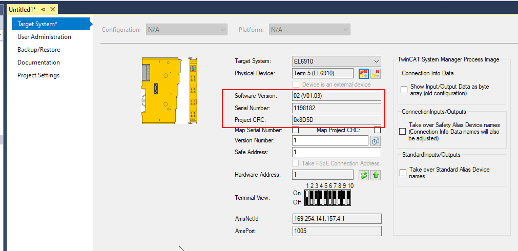
The Target system is changed to EL6910 and the software Version/Serial Number/Project CRR is read from your device.
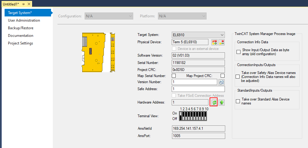
Update Hardware Address
Let’s update the Hardware Address again.
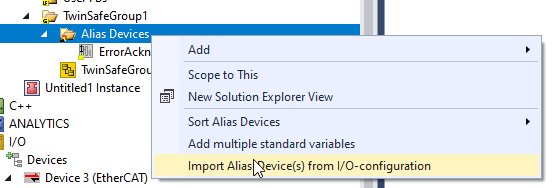
Import Alias Device(s)
Now we can import the EtherCAT Terminal from your EtherCAT network to the safety project.
Go to Alias Devices>Right Click>Import Alisa Devices(S) from I/O-Configuration.
FSOE Terminal is scanned and 2 EL1904 and 1 EL2094 are installed in my network.
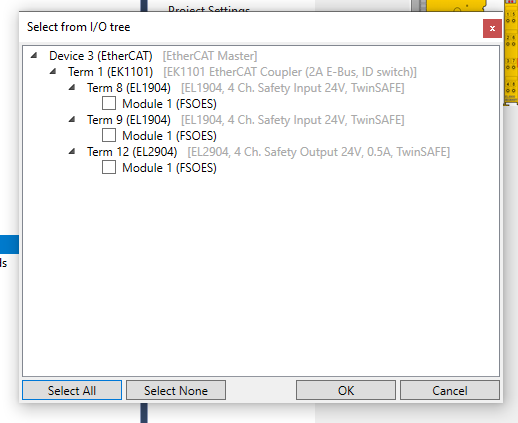
In this tutorial, Only 1 El1904 is used.

Enter the Checkbox in Term 8>Module>OK.

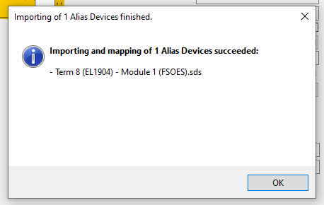
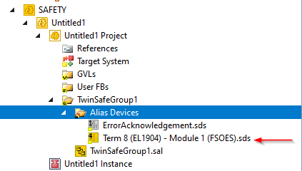
Term 8 EL1904 -Module(FSOES) is imported into your Safety Project.
Check the Module
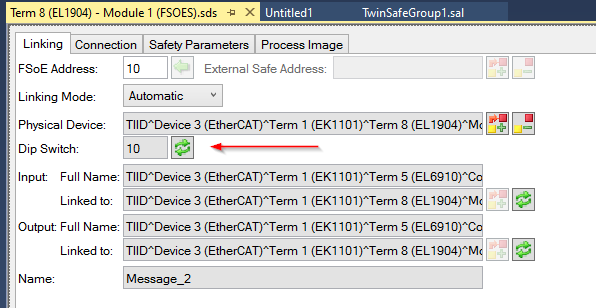
Let’s check the Status of your EL1904.Go to TwinSafeGroup1>Alias Device>Term 8(EL1904) – Module1(FSOES) and Double Click it.
The FOSE Address or DIP switch setting can be confirmed here.
An update button can allow you to refresh the current setting.
Parameters
All Parameters in each channel can be configured in the “Safety Parameters” Tab.
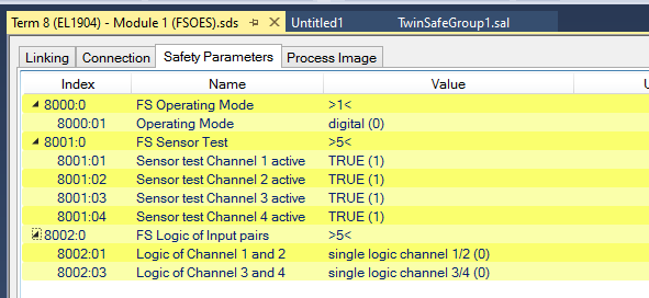
For Example, Let’s configure the Signal type of Channel1 and 2 with a Double Click.

A Set Value Dialog Popup is shown.
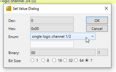
We can configure the Channel Type in the Enum field , and Single Logic Channel ½ is used in my tutorial.

Safety Program
Edit the Safety Group
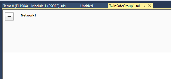
Now we can create the Safety Program – Click the TwinSafeGroup1.sal.

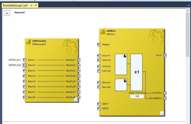
Safety Program Editor is shown.
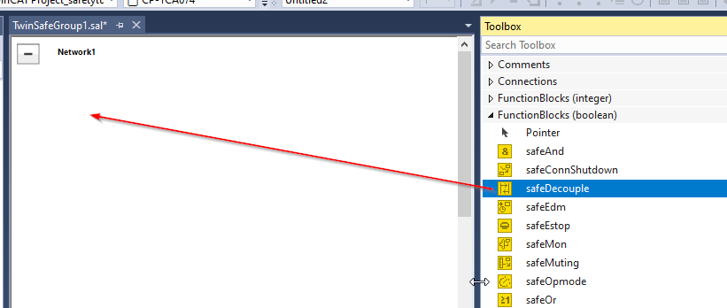
Add SafeDecouple
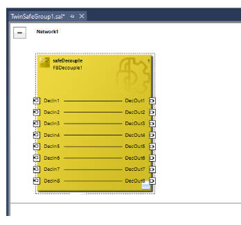
Drop the safeDecoupler Function Block from Toolbox to Network1.
rename the instance of safeDecouple Function Block as FBDdecouple1.
Add safeMon
Then we add the safeMon Function Block from Toolbox to Network1.

The Function Blocks required for the safety program are now available.

Add Variables
We can Assign the DecIn1 Input with the safeDecouple Function Block.
Choose DecIn1>Right Click > Add New Variable.

Enter your Variable Name.
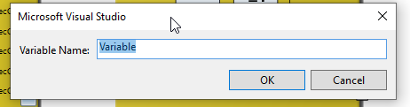
Variable Name “ESTOP_CH1” is used in my case.
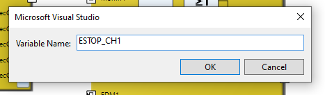
Now the DecIn1 is receiving the Signal From ESTOP_CH1 and Just do the same operation for DecIn2.

DecIn2 is connected with Safety Variable “ESTOP_CH2”.
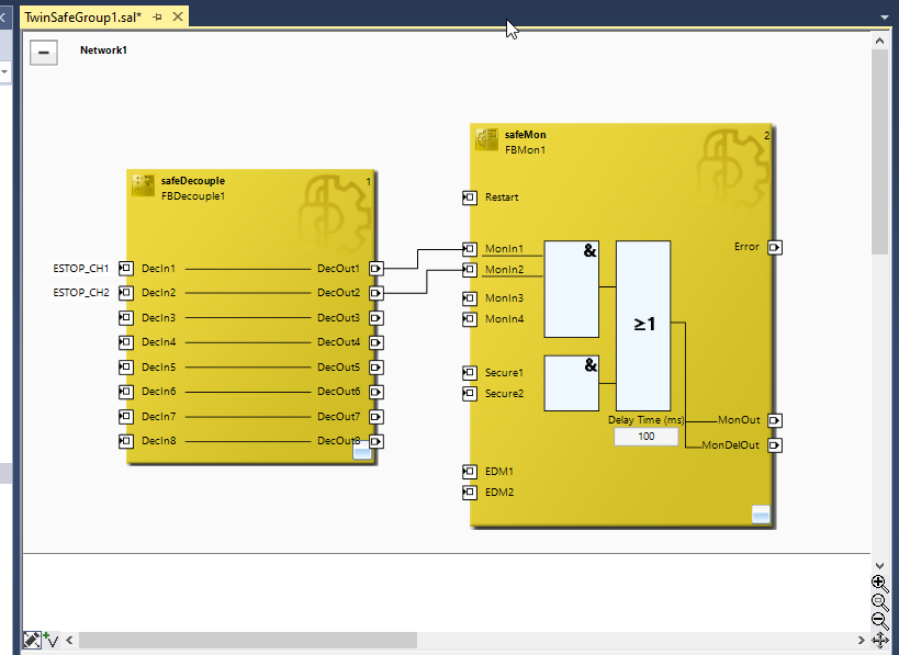
Link to safeMon Input
Then we can Connect the Output of the safeDecouple Function Block to MonIn1 in the safeMon Function Block.

Just like this.

The Output of DecOut1 and DecOut2 is connected to MonIn1 and MonIn2.
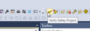
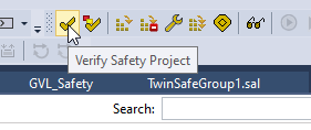
Verify Safety Project – 1 st time
Let’s use the “Verify Safety Project” function to verify the Safety project.
Error is shown and let’s check what happens inside.
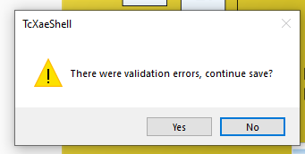
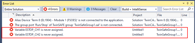
There are 4 Errors in the Error List.
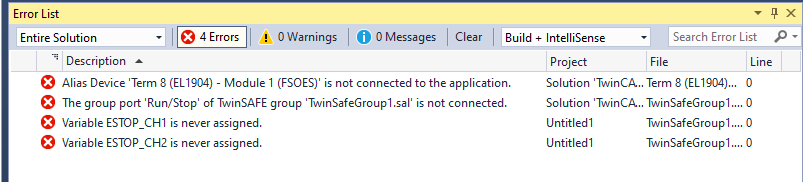
Let’s solve the “Variable ESTOP_CH1 is never assigned” and “ESTOP_CH2 is never assigned “Error first.
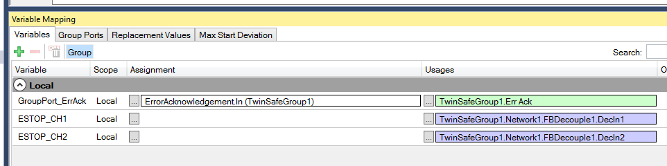
Variable Mapping
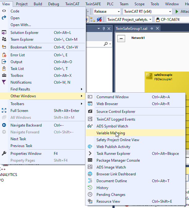
Open the Variable Mapping Tab.
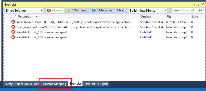
Or you can view the Variable Mapping by View>Other windows>Variable Mapping.
A variable mapping screen is shown.we need to assign all the variables in the safety project while using TwinSAFE.
Map ESTOP_CH1
Let’s define the ESTOP_CH1 First. Go to the Assignment field and click the … Button.
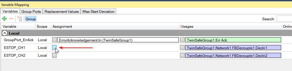
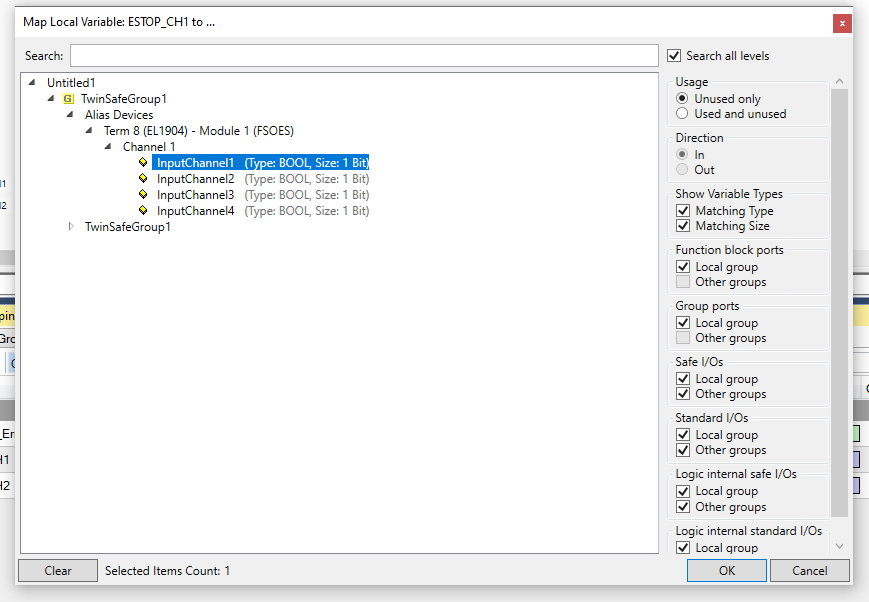
A Mapping Screen is shown.

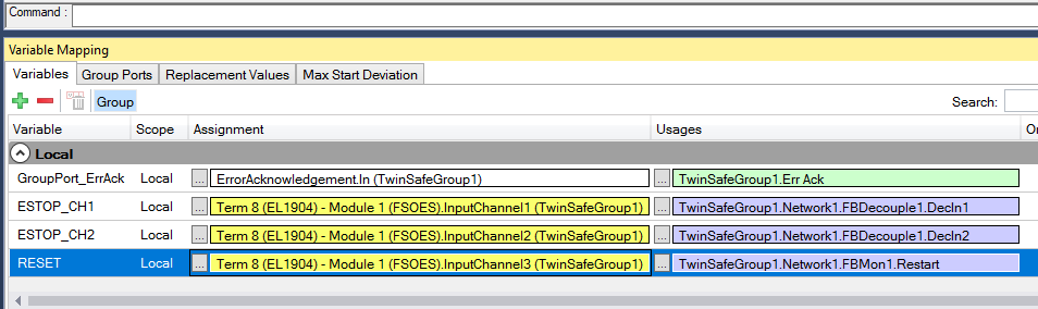
The ESTOP Signal is wired in Channel1 of EL1904 , with an ESTOP_CH1 variable name. Go to TwinSafeGroup1>Alias Devices>Term8(EL1904)>Channel1>Select Input Channel1>OK.
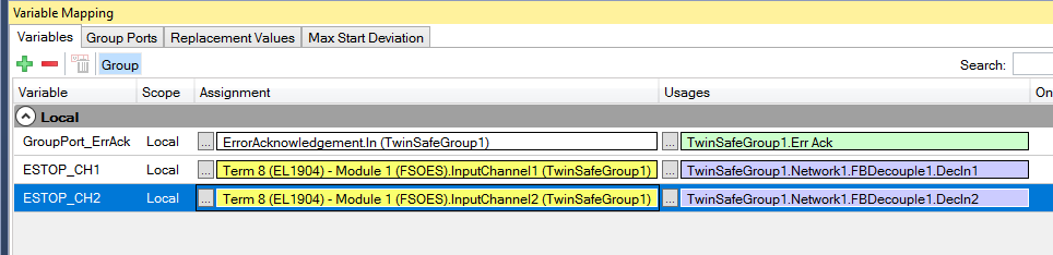
Done! Safety Variable ESTOP_CH1 is linked to the EL1904 Channel1.

Just do the same operation to the Ch2 with the variable ESTOP_CH2.
Map Reset Signals
Then we can Link the Reset Signal in the safeMon Function Block to our EL1904 Channel.
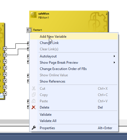
Select the Restart>Right Click>Add New Variable to create a new Safety Variable.
Verify Safety Project – 2nd time
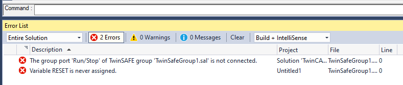
While we compile the project, a Group port ‘Run/Stop’ is not connected error is shown.
Map Reset Signals
Reset Signal is wired to EL1906 Channel3, doing the same operation with TwinSafeGroup1>Alias Devices>Term8(EL1904)>Channel1>Input Channel3.
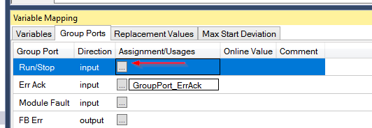
Map Run/Stop Group port
Now we need to solve the Non-assign problem of the Run/Stop Group port.Go to Variable Mapping>Open the Group Ports Tab,, you can see a Run/Stop signal in here.

Add GVL in Safety Project
For linking the Run/Stop signal, we can create a Safety Global Variable list in the safety project. Go to GVLs>Right Click>Add>Global Variable List.

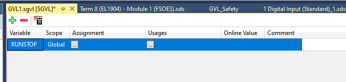
A Safety Global Variable list is inserted and please press the “+” Button to add a new safety variable.

Variable1 is defined.

Change the variable name to “RUNSTOP”.
Map it
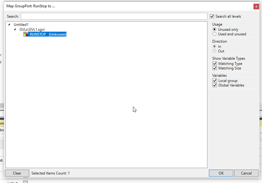
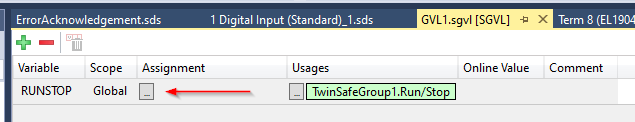
Now we can go back to the Variable Mapping Screen and press the … button in the Assignment/Usages field.
Select the Safety variable that you defined before and OK.
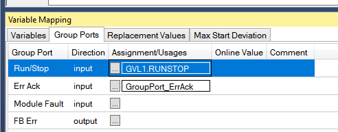
Done!
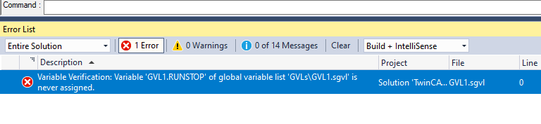
Verify Safety Project – 3rd Time
Let’s try again!

But the RUNSTOP signal is not Assigned error is still occurring.
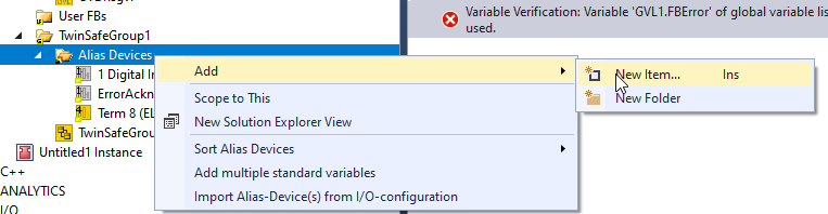
Add Digital Input Channel
We need to Link the Run/STOP signal with the standard program and a “Digital Input” must be defined in the “TwinSafe Group”.
Go to TwinSafeGroup1>Alias Devices>Right Click>Add>New Item.
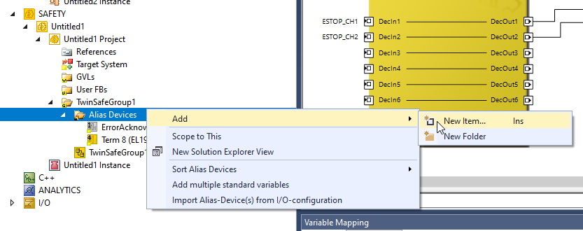
Go to Standard>Select “1 Digital Input(Standard) “ and Add it in your project.

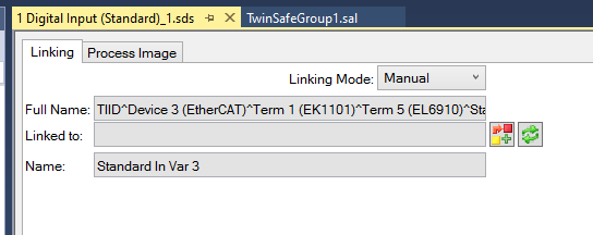
”1 Digital Input(Standard)” is inserted in your TwinSafeGroup Project and please double click it.

A linking screen is shown and lets you link the variable between the Digital input object and the standard variable inside your User program.
Create Process Output
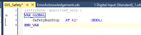
Go back to our PLC project and Select GVLs>Right Click>Add>Global Variable List.

Enter your GVL name and OK.

Define the Process Output variable.(Do not forget to add the %Q* keyword)
Compile
Go to Build>Build Solution to Build your Project.

Link to Standard Project Variable
Double Click the “1 Digital Input” Object that you inserted before.

Click the Link Button.
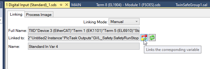
Select the Variable that you defined inside the user program,Done!

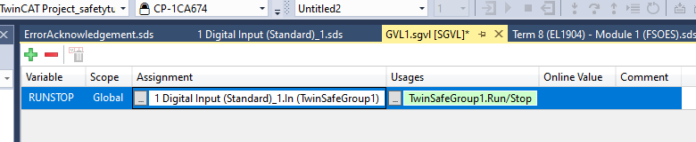
Map
Now we can assign the RUNSTOP variable in our Safety Global Variable list.
Expand Alias Devices>1 Digital Input(Standard)>Channel 1 > Select IN>Ok.

The RUNSTOP variable is linked.
Verify Safety Project – 4th time
Let’s Verify our Safety Project again.
Umm..In this time, ”At least one output mapping should be exist” error is occurred.

Actually Inside your Variable Mapping Windows, there are also some output Variables inside and you need to assign at least one in your Safety Project.
Mapping To Output
Our First Target is verifying the safety project without Error. Let’s assign FB Err in our Safety Project.

Add Normal Digital Output Channel
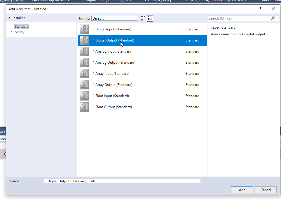
Go to Alias Devices>Add>New Item.
Choose Standard>1 Digital Output(Standard) and Add it.
Create Process Input
GO back to your Standard PLC Project and define the Process Input variable.(Please do not forget the AT %I* keyword)

Compile
Go to Build>Build Solution to Build your Project.

Link to Standard Project Variable
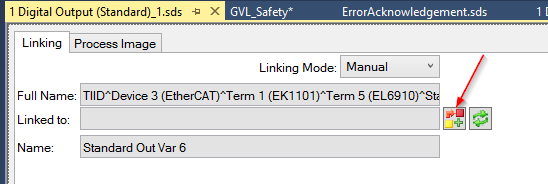
Double Click the “1 Digital Output” Object.
Click the + Button.
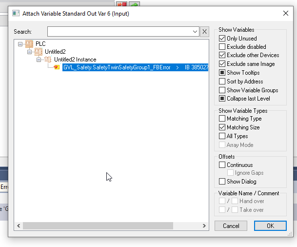
Choose the Process Input variable that we defined before.
Done!
Verify Safety Project – 5th Time
Let’s Verify our Safety Project again.

Umm.. An error is shown and informs us that the FB Error Variable is not used in our safety project.

Mapping
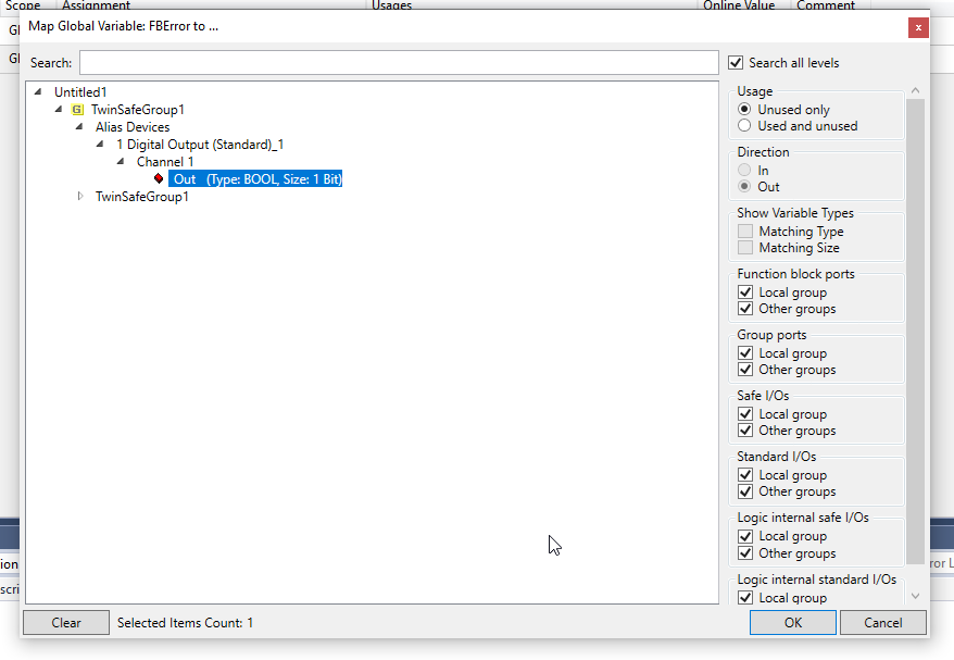
Open the Safety GVL>Go to FB Error>Click the … Button.
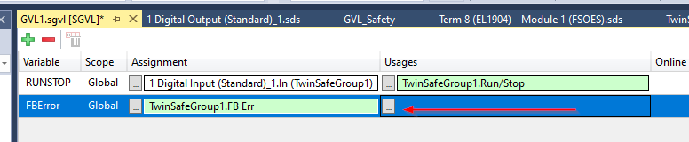
Link the “1 Digital Output” variable.
Add ESTOP OUTPUT
Based on the compile errors so far, I will explain the exact construction procedure at the end of linking with the variables of the Standard PLC Project at MonOut.
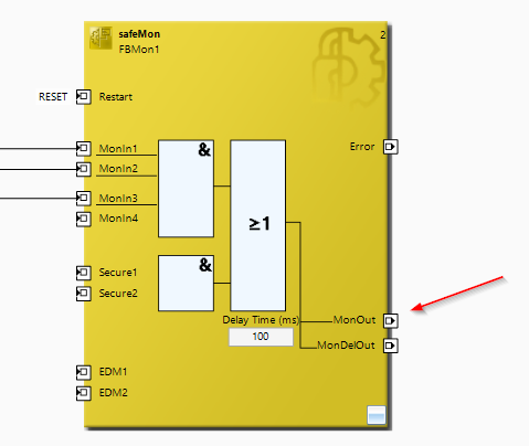
Add New Variable in Function Block
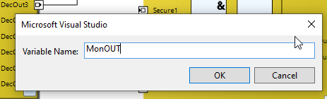
Right Click the MonOut>Add New Variable.
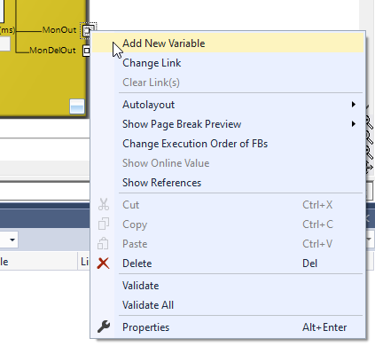
Enter the MonOut Variable name and OK.
Add Digital Output(Standard)
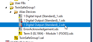
Go to Alias Devices>Add>New Item.

Select 1 Digital Output>Add it.
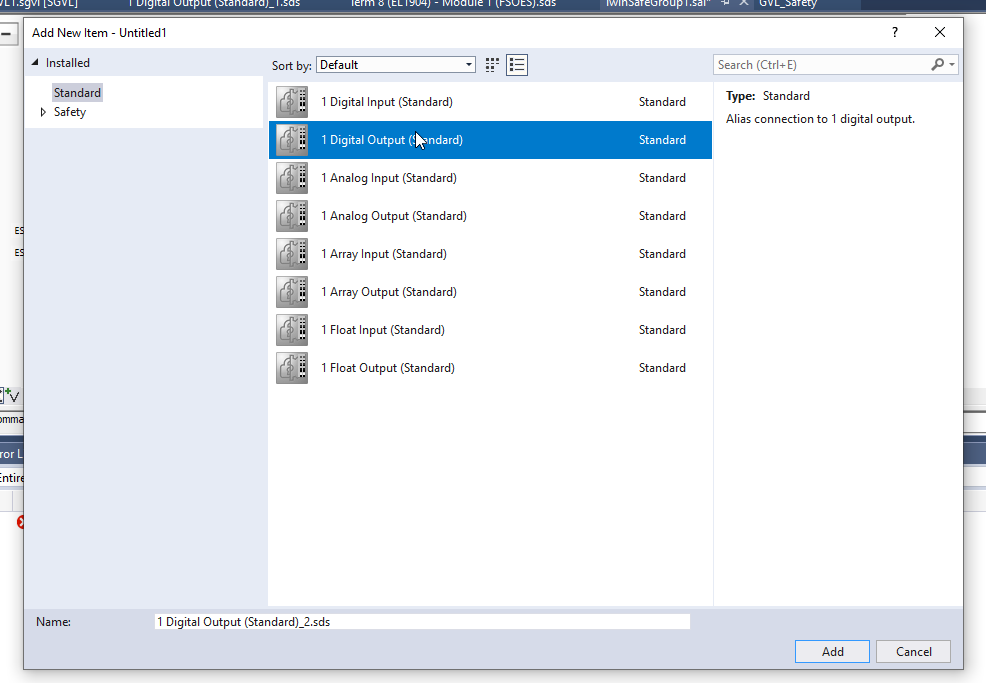
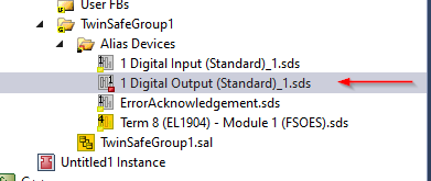
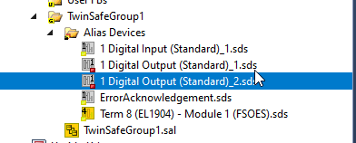
1 Digital Output_2 is inserted.
Link to Usage
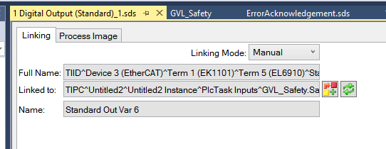
Open the Variable Mapping>Select the MonOut >Click the … Button.

Select the 1 Digital Output(Standard)_2 that we defined before and add it.
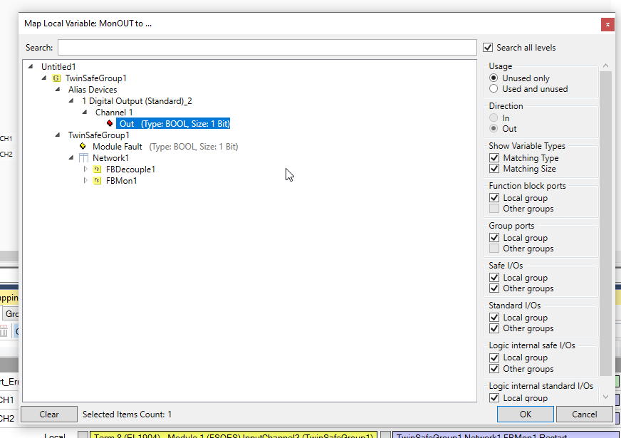
Done!

Add Process Output in Standard Program
Open the GVL in your user program and define the process Input variable.(Do not forget the AT %I* keyword)

Link to Digital Output
Click the 1 Digital Output(Standard) Object.
Press the Link Button in the Linking tab.

Select the process input that we defined in the previous step and Add it.

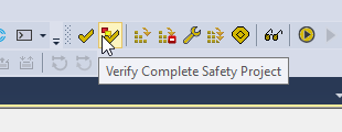
Verify
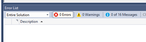
Let’s Verify our Safety Project again.
Done!! NO Error occurred in this time.
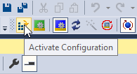
Download Configuration
Download your Configuration with the Activate Configuration Button.
OK.

Restart your TwinCAT Runtime and Turn to Run Mode.

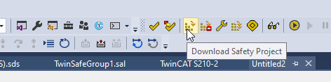
Download Safety Project
Download the Safety Project into EL6910.
Login Screen is shown. Enter Administrator as the User name.
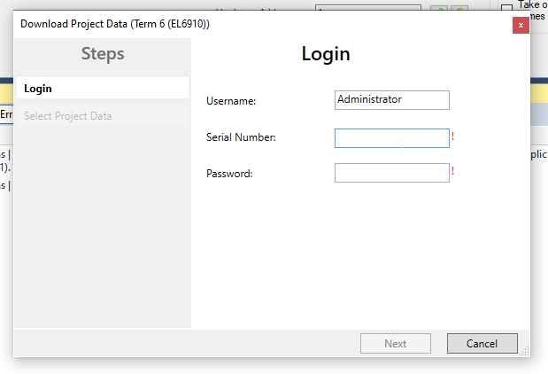
Enter the serial number of your EL6910.
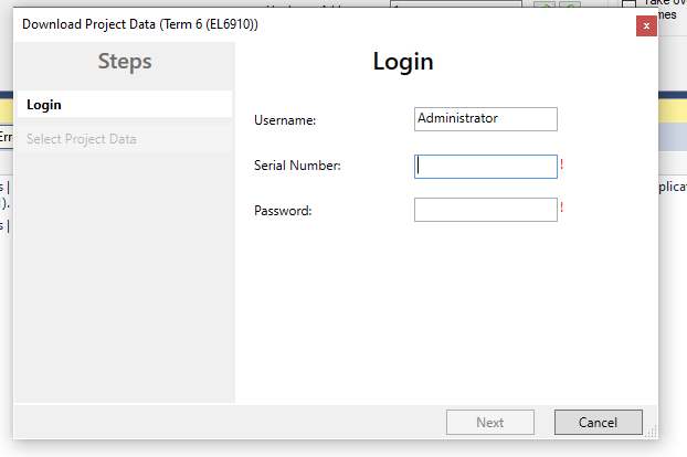
You can find the Serial Number from the Target System view.
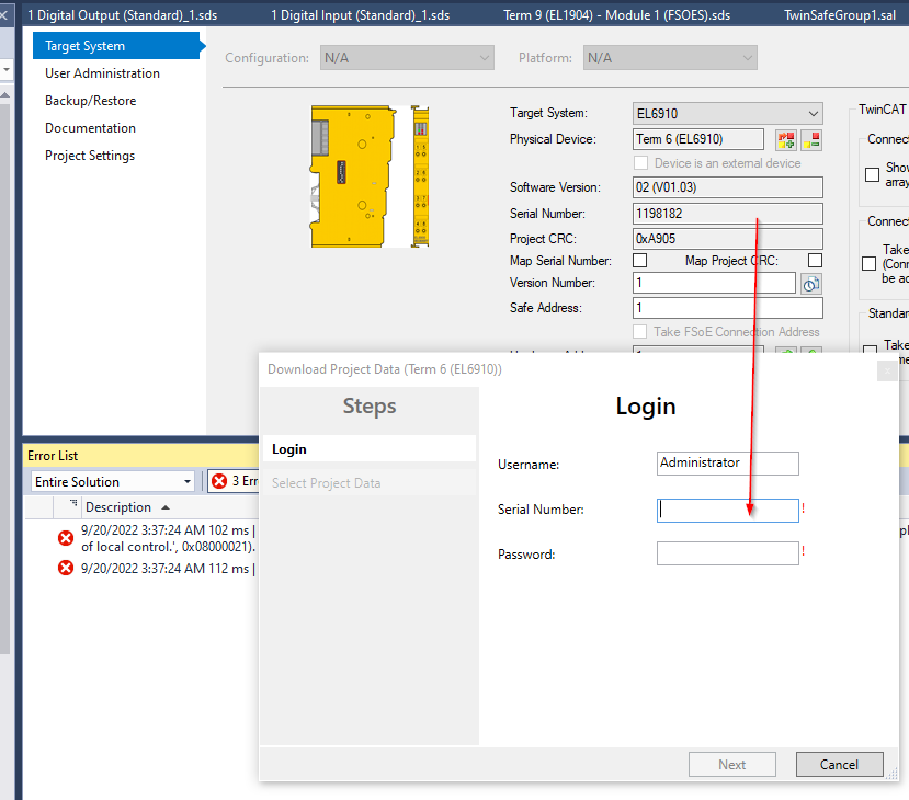
In this tutorial, the serial number of my EL6910 is 1198182.
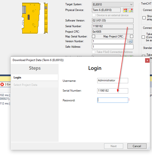
The default password is TwinSAFE.
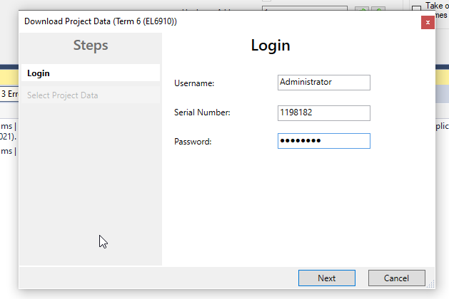
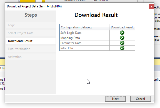
If your User name/Serial Number/Password are correct, you will see a “Select Project Data” screen.In this tutorial, “Complete Project Data” is chosen and press Next.
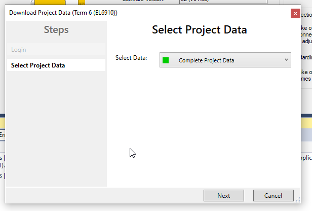
Project is downloaded and Press Next to continue.
Enter the Checkbox and Next.

Enter the Password again to activate the Safety Application.
The default password is TwinSAFE.

Login
Download your User program to the TwinCAT Runtime.

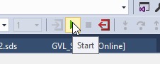
Start
Start your Application.
Result
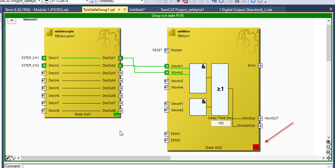
Press the “Show Online Data” Button to change your TwinCAT to Monitor Mode.
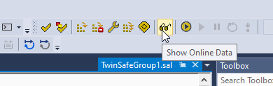
Great!Now we are in Monitor Mode.

But the Safety Group is in stop state, and also there is a red icon in all your Safety Function Block.
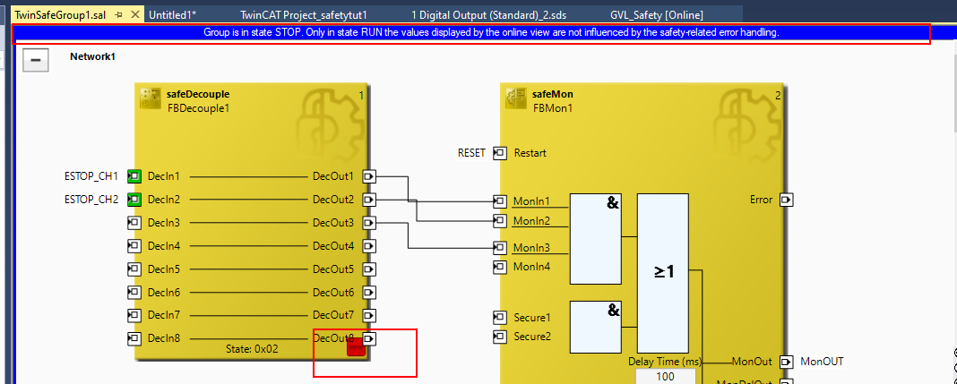
Go to your standard User Program and Change the value of SafetyRunStop variable to True.
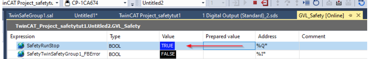
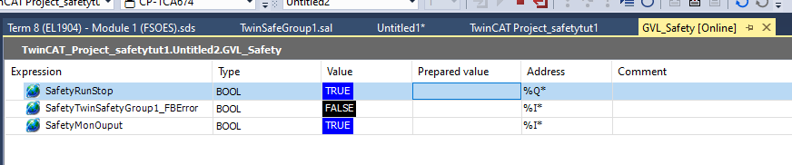
Done!Your Safety Group is running.
Press the Reset button,The Safety Function block MonOut’s output will be activated.

There are some caveats to creating a Safety Program in TwinSAFE.
- All Local and Global variables must set the assigned Field set. (i.e. in the sense of input, TwinSAFE will not know where this variable feed comes from?)
- All Local and Global variables must also have a Used Field set. (i.e. in the output, what variable will this variable output to at the end)
- TwinSafeGroup RUN/STOP variables must always be Assigned
- At least one port output of TwinSafeGroup must be assigned.
- A “Standard Digital/Analog” module is required for data exchange between the safety program and the standard program.
- Define the variable as Process IO in the Standard PLC Program.AT %I*/ AT %Q*
- Default Username is Administrator and Default Password is TwinSAFE.