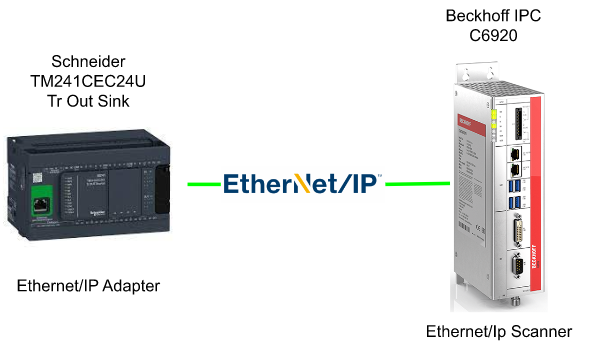
In this tutorial I will show you how to configure a Ethernet/IP Network by using Beckhoff IPC C6920 with TF6281 as Scanner and Schneider TM214 CPU as an Adapter, But Also create an IO Data Verification program to check the consistency of the Process Input/Output.
This is a program that I am using in my work to check the Process IO data..
Let’s start!

Thanks!
Because of Beckhoff Japan and mana Design works that lend the devices to me – I can create this post.
Beckhoff Japan
IPC6920-005 was lent by Beckhoff Japan, a Japanese subsidiary of Beckhoff. Founded in 1980, Beckhoff Automation is a German company at the forefront of the introduction of open automation systems based on PC-based control technology.
Beckhoff Japan Corporation Beckhoff Automation Co., Ltd. established its head office in Yokohama in 2011 and the Nagoya office in 2017.

Here is the Home page of Beckhoff Japan.
https://www.beckhoff.com/ja-jp/
Mana Design Works
Siemens SINAMICS S210 was lent by Mana Design Works.
Mana Design Works is an official solution partner of Siemens ,headquartered in Osaka, and always make optimal proposals with Siemens CPUs, HMIs, Drives, Motion Controllers, and SCADA.

Here is the homepage of Mana Design works.
Implementation
Here is the configuration in this Tutorial.
Schneider Side
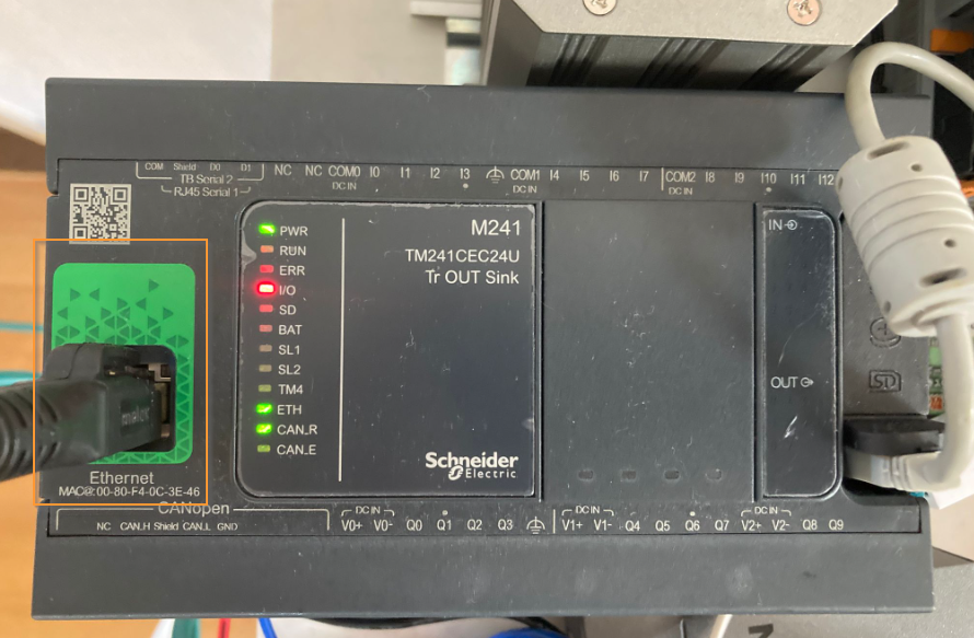
Let’s configure the Schneider TM241 PLC First. The Ethernet port that is shown below is used as an Ethernet/IP network.
New Project
Launch the Machine Expert Logic Builder, File New Project to create a new Project.

Choose the Controller Type(in my case is TM241CET/U) , Then enter your Project name>OK.

New Project is Created.
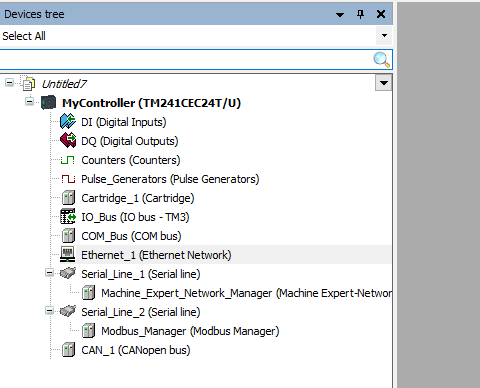
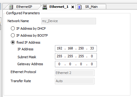
Configure Ethernet Interface
Double Click the “Ethernet_1* to configure Ethernet Interface.
You can configure the IP by select the fixed IP Address.

As I mentioned before, 192.168.250.33/24 is used in here.
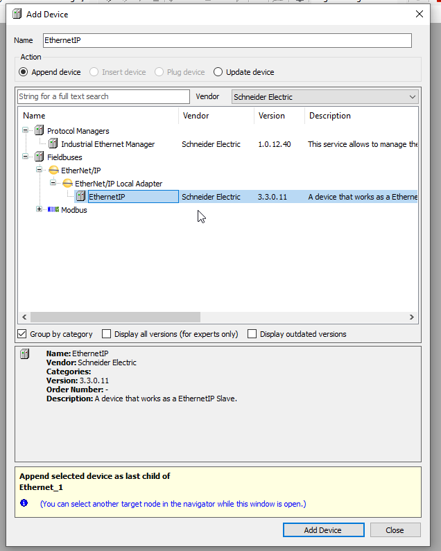
Configure an Ethernet/IP Adapter
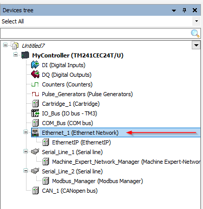
Right Click Ethernet_1>Add Device.

Expand Fieldbuses>EtherNet/IP>EtherNet/IP Local Adapter>EthernetIP>Add Devies.
Assembly Parameters
Now we can configure the Input and Output Assembly and Exchange Data size.
Please Double click the “EthernetIP” icon.

EtherNetIP Tab is opened.
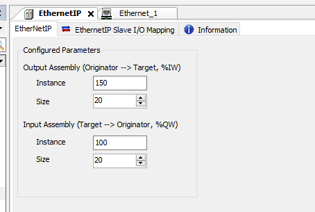
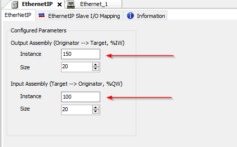
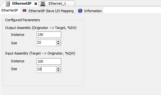
Instance Numbers
By Default, Instance 150 is for Originator to Target and 100 is for Target to Originator.
I will set these Instance settings as default.
Size(Word)
And also the default data exchange size is 20 words.

I will change 32 words in my tutorial.
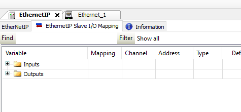
I/O Mapping
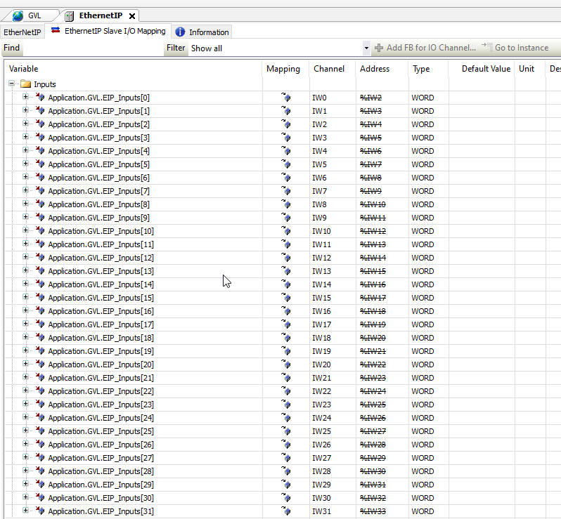
Open the EthernetIP Slave I/O Mapping Tab, Inputs and Outputs variables are shown.
Because the exchange default size is 20 words, Machine Expert Logic Builder will auto assign iwEthernetIP_IWx as the Inputs variable.
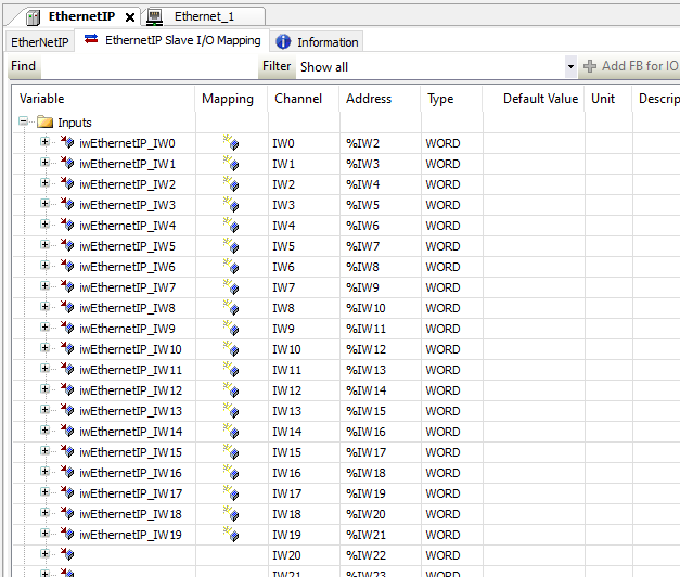
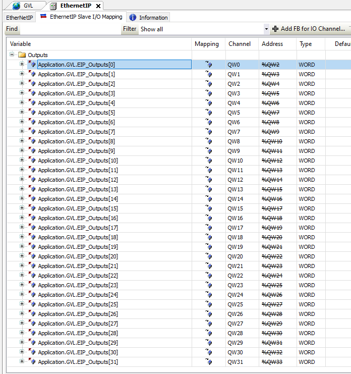
Because the exchange default size is 20 words, Machine Expert Logic Builder will auto assign qwEthernetIP_QWx as the Output variable.

Export EDS
Right click the EthernetIP icon>Export as EDS to export the EDS File.
we will use this file in TwinCAT Side.

Please choose your file path to save.
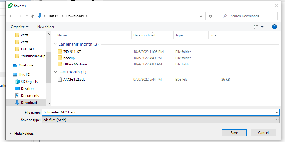
Done!
Program
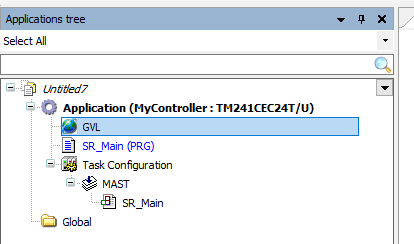
Open the Applications tree tab.
GVL
Program editor is shown and I will create some variables inside GVL for ethernet/IP adapter data exchange.Double Click the “GVL” Icon.
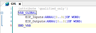
GVL tab is opened.

Define 2 arrays of 32 words – we will map these variables to Ethernet/IP Adapter.
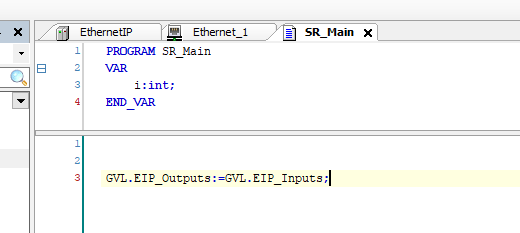
Main
In the SR_Main Program, we just need to transfer back all the Input data to output and Make a loop back.
Mapping Again
Now we can mapp again all the Ethernet/IP adapter variables.
Input
Here is the input mapping, the variables that are defined in GVL are re-mapped.
Output
Here is the Output mapping, the variables that are defined in GVL are re-mapped.
Login
The Configuration is done in the Schneider Side – Now we can download the project to the CPU.Click the “Controller” Icon>Choose your controller>Login.

Press Yes to download the project.
Schneider side is ready now!

TwinCAT Side
Now we can implement the TwinCAT Side.As I mentioned before, an IO Data Verification program is used to check the consistency of Input/Output Data – And here is the flow.
TwinCAT3 will Check the Scanner status first, then check the Adapter connection(In this side TM241 Schneider PLC is used), after that random values are generated and written into all output variables, and Check if Input data is 100% the same as output data or not.
If the input data is not the same as Output data, An Error Flag is set and indicates the status.
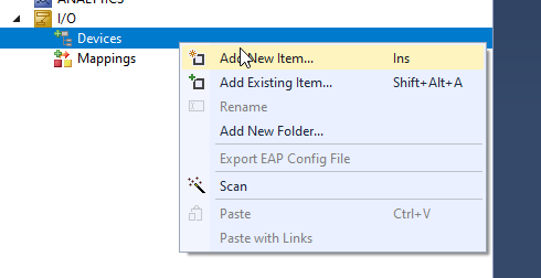
Configure An Ethernet/IP Scanner
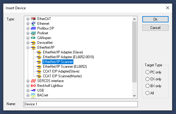
Open your TwinCAT3,Go to I/O>Devices>Add New Item.
Expand EtherNet/IP>EtherNet/IP Scanner, click Ok.
Choose the Ethernet Interface that is connected in your ethernet/IP network.
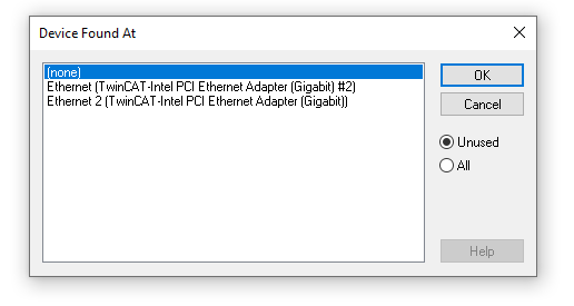
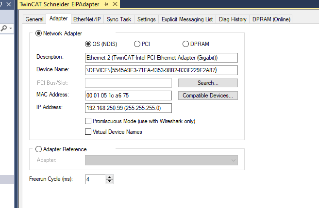
Please double click if the interface that you selected is correct or not.
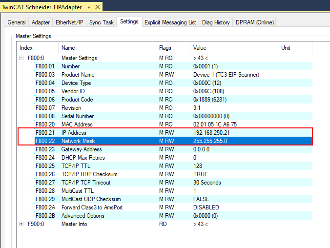
Configure the IP
Open the Settings Tab and Configure the ip address in F800:21 and F800:22.
Task
Open the Sync Task Tab>Select Special Sync Task option>Create new I/O Task.
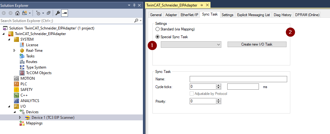
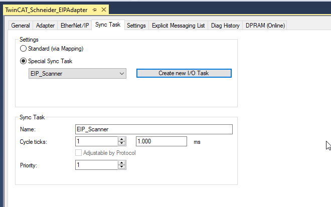
Enter your Task Name>OK.

Ethernet/IP Task is created – and you can assign the cycle ticks that depends on your application.
Configure Target
Now we can configure the Adapter.
Import EDS
Right click the Scanner that you created in the previous step>Import EDS File.
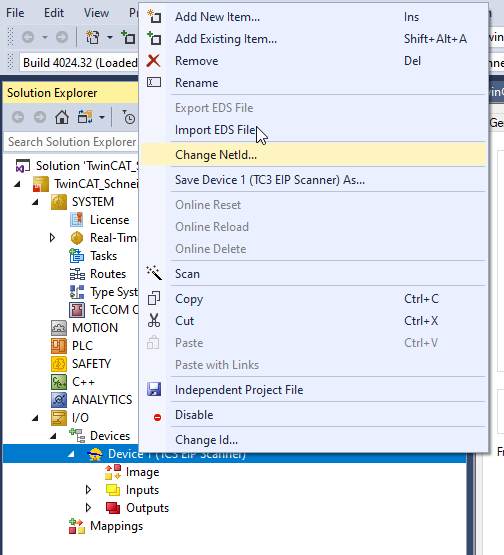
Select the EDS File >Open.

EDS File is imported!
Insert Schneider Adapter
Right Click the Scanner>Add New Item.

Open Schneider Electric>Select TM241_xxxx >OK.

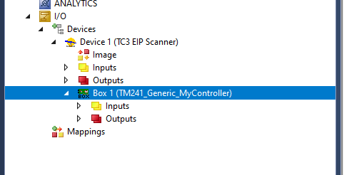
TM241 Ethernet/IP adapter is inserted.

Configure IP
Right Click the TM241 Ethernet/IP Adapter>Change IP Address.

Enter the IP address and OK.

Once the Ip is configured, the icon will change.
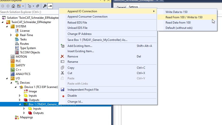
Append IO
Right Click the Box1>Select “Append IO Connection>Read From 100/ Write to 150”.
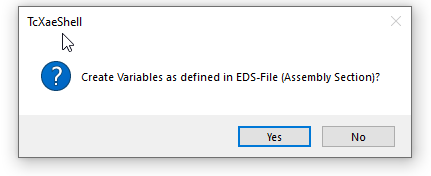
Yes.
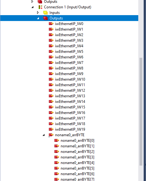
Connection 1 (Input/Output) is inserted in your Box.

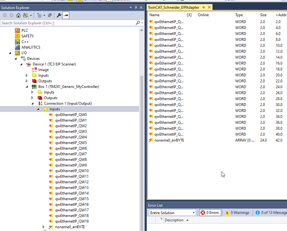
Mapping-input
As you see, because the Connection is inserted from EDS File,variables are strange.Although the total Exchange is 32 words, some variables are grouped as “noname0_arrBYTE”.
Mapping-Output
As you see, because the Connection is inserted from EDS File,variables are strange.Although the total Exchange is 32 words, some variables are grouped as “noname0_arrBYTE”
Add PLC
Go to PLC>Add New Item to create a software PLC in your project.
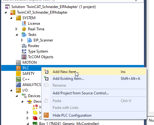
Choose Standard Project>Add.

A Standard PLC is inserted in your Project.

GVLs(Global Variable List)
Here is the GVLs – Process Input/Output is defined here, and we will use these variables to re-map the Ethernet/IP data.
| {attribute ‘qualified_only’} VAR_GLOBAL EIP_Scanner1_Box1_Inputs AT %I*:ARRAY[0..31]OF WORD; EIP_Scanner1_Box1_Outputs AT %Q*:ARRAY[0..31]OF WORD; END_VAR |
DUT
DUT_TF6281_DevState
This is the status structure of the TF6281 TwinCAT Ethernet/IP Scanner.
| TYPE DUT_TF6281_DevState : STRUCT LinkError :BOOL; OutOfSendResources :BOOL; WatchdogTrigger :BOOL; MasterNoValidIPAddr :BOOL; TCPUnable :BOOL; UDPUnable :BOOL; END_STRUCT END_TYPE |
You can get more information by opening the DevState variable.

The details are shown in the Comment field.

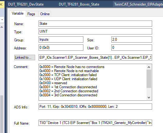
DUT_TF6281_Boxes_State
This is the status structure of the Connection status for each adapter in TF6281 TwinCAT Ethernet/IP Scanner.
| TYPE DUT_TF6281_Boxes_State : STRUCT ConnectionDisconnected :ARRAY[1..8]OF BOOL; TCPClientInitFailed :BOOL; UDPClientInitFailed :BOOL; RemoteNodeNoConnections :BOOL; RemoteNodeNotReachable :BOOL; END_STRUCT END_TYPE |
You can get more information by opening the State variable.
The details are shown in the Comment field.
Function Block
Now we can create a function block to get the status of the Ethernet/Ip Scanner and the connection between Adapter.
FB_TF6281_Status
VAR
These variables are directly mapped to the Process IO.
| FUNCTION_BLOCK FB_TF6281_Status VAR_INPUT END_VAR VAR_OUTPUT END_VAR VAR EIP_Scanner_Boxes_State AT %I* :ARRAY[1..4]OF UINT; EIP_Scanner_DevState AT %I* :UINT; END_VAR |
PROPERTY DevNormal : Bool
Get
Here is a Property to get the Scanner is normal or not.
| DevNormal:=EIP_Scanner_DevState =0; |
PROPERTY PUBLIC DevState : DUT_TF6281_DevState
Get
Here is a Property to encoder the Devstate status variable and indicate any errors.
| DevState.LinkError:=(EIP_Scanner_DevState AND 16#0001)>0; DevState.OutOfSendResources:=(EIP_Scanner_DevState AND 16#0010)>0; DevState.WatchdogTrigger:=(EIP_Scanner_DevState AND 16#0020)>0; DevState.MasterNoValidIPAddr:=(EIP_Scanner_DevState AND 16#4000)>0; DevState.TCPUnable:=(EIP_Scanner_DevState AND 16#2000)>0; DevState.UDPUnable:=(EIP_Scanner_DevState AND 16#1000)>0; |
GetBoxStates : DUT_TF6281_Boxes_State
Here is the Method to encode the Adapter status – and use a BoxNumber as parameter, the user can choose the connections that would like to check.
VAR
| METHOD GetBoxStates : DUT_TF6281_Boxes_State VAR_INPUT BoxNumber:UINT; END_VAR VAR _State:UINT; END_VAR |
PROGRAM
| IF BoxNumber>=1 AND BoxNumber<=4 THEN _State:=EIP_Scanner_Boxes_State[BoxNumber]; ELSE _State:=EIP_Scanner_Boxes_State[1]; END_IF GetBoxStates.ConnectionDisconnected[1]:=(_State AND 16#0001)>0; GetBoxStates.ConnectionDisconnected[2]:=(_State AND 16#0002)>0; GetBoxStates.ConnectionDisconnected[3]:=(_State AND 16#0004)>0; GetBoxStates.ConnectionDisconnected[4]:=(_State AND 16#0008)>0; GetBoxStates.ConnectionDisconnected[5]:=(_State AND 16#0010)>0; GetBoxStates.ConnectionDisconnected[6]:=(_State AND 16#0020)>0; GetBoxStates.ConnectionDisconnected[7]:=(_State AND 16#0040)>0; GetBoxStates.ConnectionDisconnected[8]:=(_State AND 16#0080)>0; GetBoxStates.UDPClientInitFailed:=(_State AND 16#1000)>0; GetBoxStates.TCPClientInitFailed:=(_State AND 16#2000)>0; GetBoxStates.RemoteNodeNotReachable:=(_State AND 16#4000)>0; GetBoxStates.RemoteNodeNoConnections:=(_State AND 16#8000)>0; |
POUs EIP_IOs
Finally we will create a new POUs to verify the consistency of data
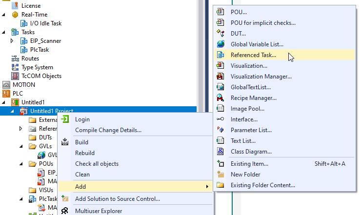
Add Referenced Task
Create new POUs. Then right click your Project>Add>Referenced Task.
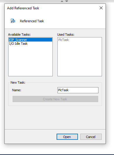
Select the Task that you created in the previous step>Open.
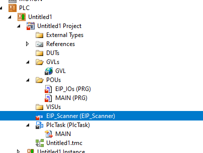
A Reference Task is created.
VAR
Here are the variables that are used inside the POUs.
| PROGRAM EIP_IOs VAR Scanner1 :FB_TF6281_Status; iCounter:INT; OutputRefleshed:BOOL; IODataChecked:BOOL; Seed:INT; Random :DRAND; DataNoSame :BOOL; TimerIOVerify:TON; TimerOutputReflesh:TON; ScannerReady:BOOL; Box1:DUT_TF6281_Boxes_State; Start2Verify :BOOL; pStart2Verify :R_TRIG; tIOVerifyTime :TIME:=T#64MS; tOutputFlash :TIME:=T#96MS; END_VAR |
PROGRAM
The program will follow the flow that mentioned before – Check the Scanner condition and the connection status between Adapter> Generate Random data and written output and the loop back is the same or not. If not, a non-rest flag will be true.
| //Get Scanner and box status ScannerReady:=Scanner1.DevNormal; Box1:=Scanner1.GetBoxStates(1); IF ScannerReady AND NOT Box1.ConnectionDisconnected[1] AND NOT Box1.RemoteNodeNotReachable AND NOT Box1.RemoteNodeNoConnections AND NOT Box1.TCPClientInitFailed AND NOT Box1.UDPClientInitFailed THEN //This Bit will never reset – for the first time CPU Start up Start2Verify:=TRUE; END_IF; //Verification will start while Scanner and Box is ready. pStart2Verify(CLK:=Start2Verify); //IO Verification //Read IF TimerIOVerify.Q THEN FOR iCounter:=0 TO 31 DO IF GVL.EIP_Scanner1_Box1_Outputs[iCounter] <> GVL.EIP_Scanner1_Box1_Inputs[iCounter] THEN DataNoSame:=TRUE; END_IF END_FOR OutputRefleshed:=FALSE; IODataChecked:=TRUE; END_IF; //Write IF TimerOutputReflesh.Q OR pStart2Verify.Q THEN FOR iCounter:=0 TO 31 DO Random.Seed:=Seed; Random(); GVL.EIP_Scanner1_Box1_Outputs[iCounter]:=LREAL_TO_WORD((Random.Num*100)); END_FOR OutputRefleshed:=TRUE; IODataChecked:=False; END_IF //Time Reflesh //IOVerification TimerIOVerify( IN:=OutputRefleshed AND NOT IODataChecked ,PT:=tIOVerifyTime ); //Output Flesh TimerOutputReflesh( IN:=IODataChecked AND NOT OutputRefleshed ,PT:=tOutputFlash ); |
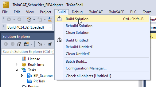
Build
Build>Build Solution to compile the project.
Link the variables
Inputs
Delete all the input variables that were created from the default EDS file.

Right Click>Add New Item again.
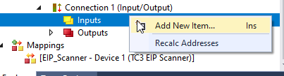
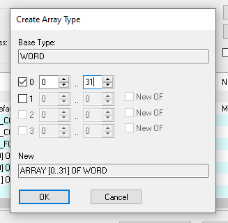
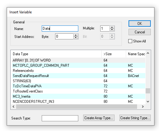
Enter your Variable Name>Select Word as the Data type and Click the “Create Array Type” button to create an Array variable.

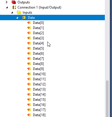
Define an array[0..31]of WORD variable.
Done!
Outputs
Delete all the Output variables that were created from the default EDS file.

Right Click>Add New Item again.

Select the Array[0..31] OF WORD>OK.
DevState
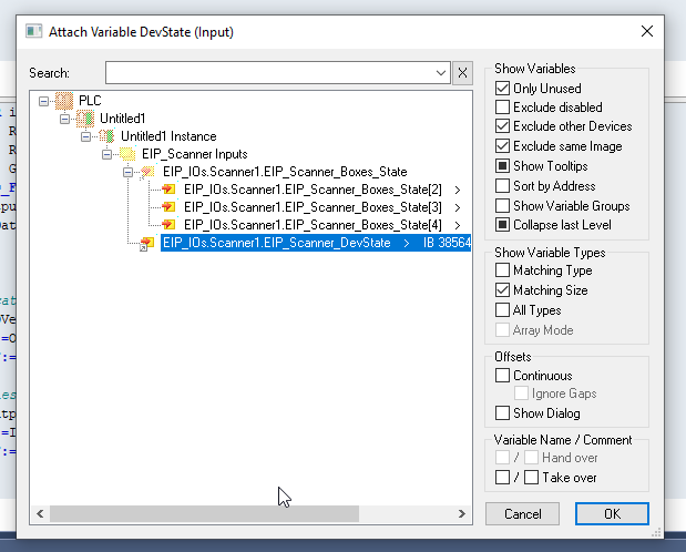
Then we can Link the DevState.Right click the DevState>Change Link.
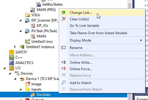
Choose the Variable that you defined.
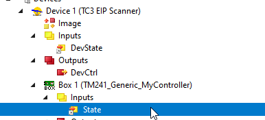
State
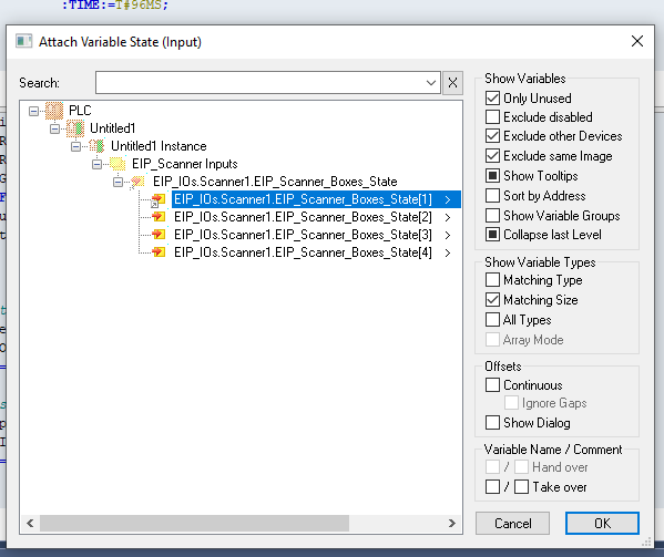
Finally we link the State variable to get the connection status between TwinCAT and TM241.
Right Click>Change Link.

Choose the variables that defined in the previous step.
Result
Firstly TM241 Schneider PLC is started without any Error.

And you can see the CIP I/O Packages are exchanged by using Wireshark.
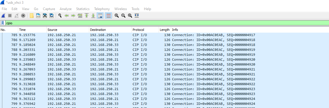
Some random data is received from TwinCAT
In TwinCAT Side, some random side is sent to Schneider TM241 PLC and Data is loopback.
Here is the LED Status of Schneider TM241 while in normal status.
Source Code Download
Please download the source code from this link:
https://github.com/soup01Threes/TwinCAT3/blob/main/TwinCAT3_Schneider_TM241_EIP_Project.7z