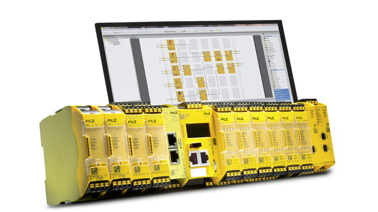
This is a new series! In this article on Pilz’s compact Safety Controller PNOZmulti 2, we will start with the start-up and tool operation.
Let’s get started!
Thanks!
The equipment used in this article was loaned to us by PILZ JAPAN.
PILZ
PILZ supports factory automation sites as a total solution supplier with solutions in safety and automation technology, guaranteeing the safety not only of people, but also of machines and the environment, and how safely machines and equipment can be operated. Pilz has 42 subsidiaries and branch offices worldwide and is active in various fields such as packaging, automotive industry, robotic applications, as well as wind power and railroad technology.

Office:
ピルツジャパン株式会社
〒222-0033
横浜市港北区新横浜3-17-5
いちご新横浜ビル 4階
HP
PNOZmulti 2?
The flexible configurable safety miniature controller PNOZmulti 2 is ideal for implementing multiple safety functions in plants and machines, since the PNOZmulti 2 system can be adapted to the size of the plant or machine and is available in a large number of the most diverse modules and various base units, application design flexibility.
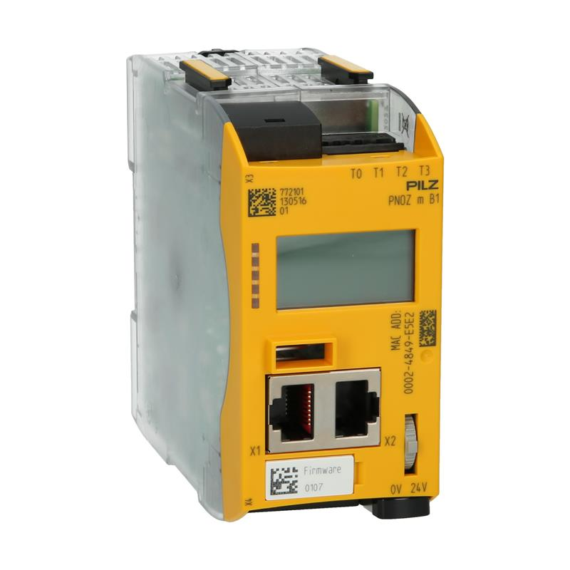
Additionally, the base unit is equipped with an illuminated display for quicker diagnosis.
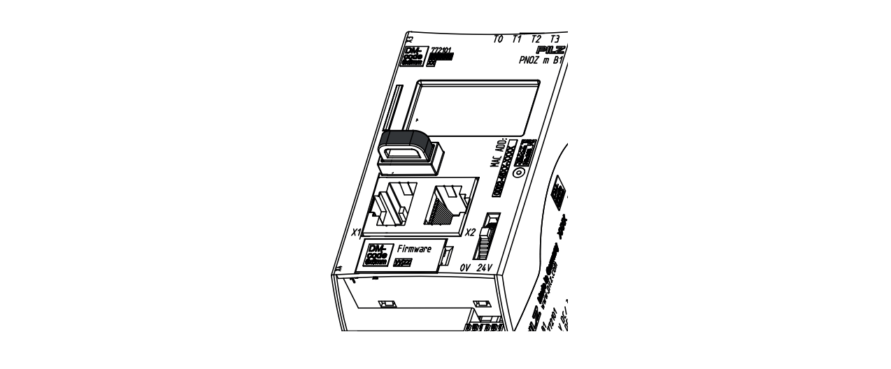
Layout
Here is the Layout diagram for PNOZmulti 2.
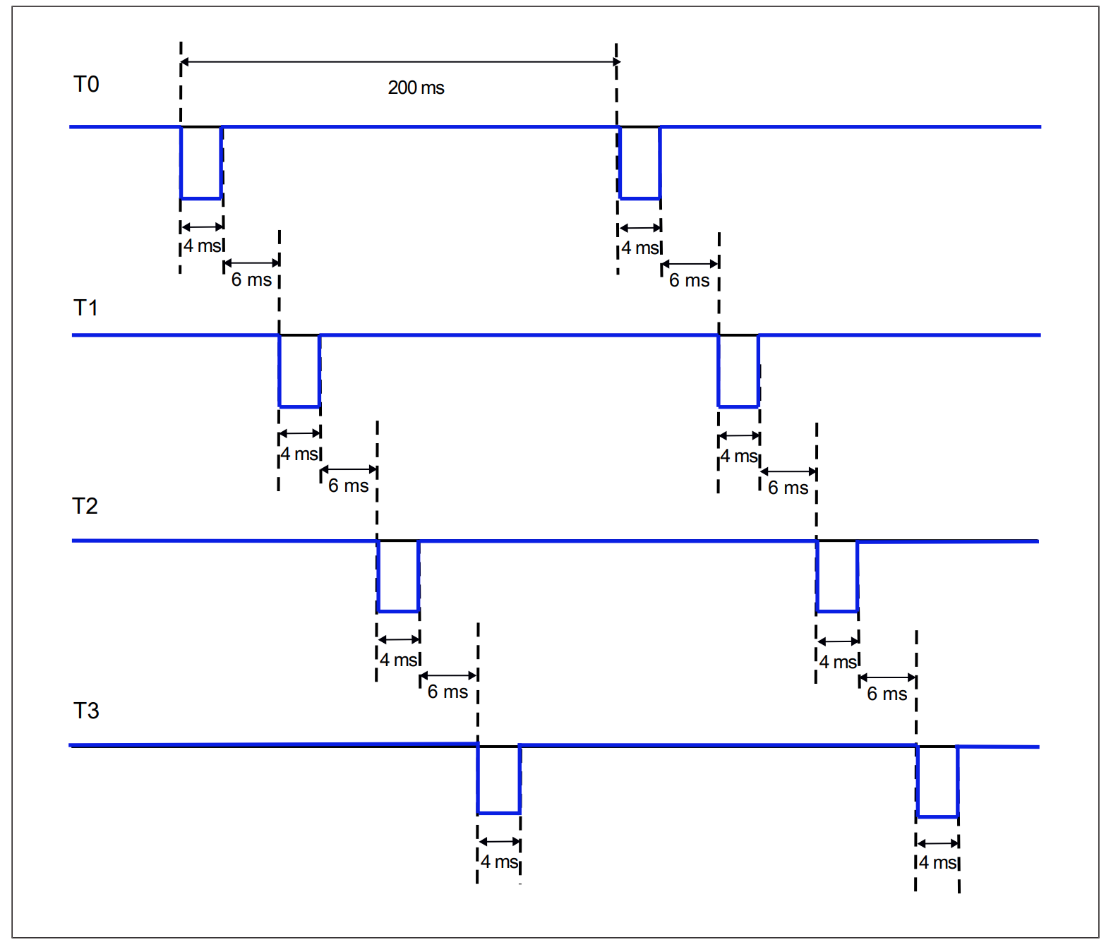
Detection of shorts across contacts
PNOZmulti 2 uses different test pulses (test pulse 0 (T0) to test pulse 3 (T3)) Four test pulse outputs can be used to detect a short circuit between inputs.
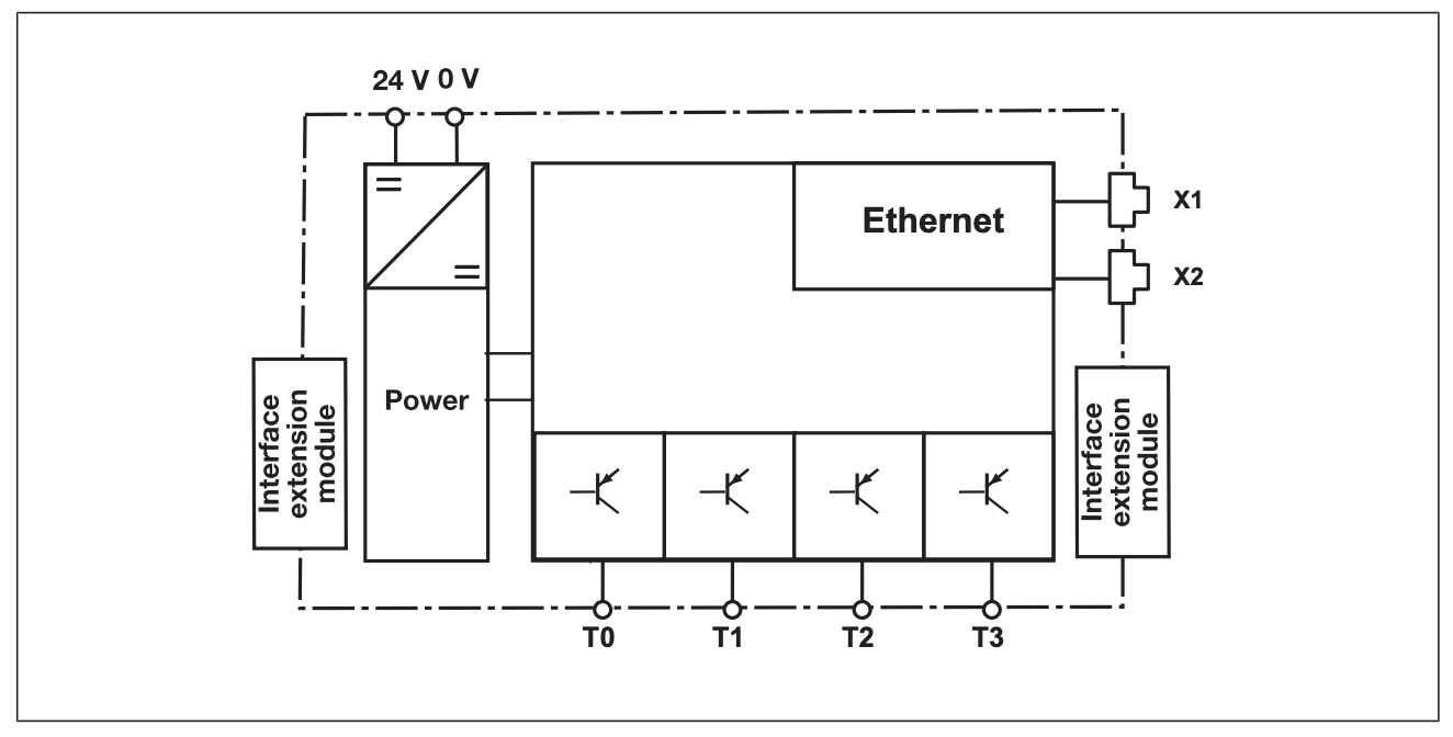
Block Diagrams
Here is the internal block diagram of PNOZmulti 2.
 Ethernet interface
PNOZ m B1 can perform the following functions using the following Ethernet interfaces
- Manage and Download Projects
- Read diagnostic data
- Configure virtual inputs in standard functions.
- Read virtual outputs in standard functions.
Information on diagnostics via the interface can be found in the document PNOZmulti, please refer to the instruction manual for more information.
Use USB memory
Multiple projects can now be stored on the included USB memory stick, one of which can be activated and run on the base unit.
When using a USB flash drive, there are a few things to keep in mind.
- USB memory must be connected at all times during operation.
- For example, to copy a project, you can remove the USB memory stick and connect it to a PC or to another base unit PNOZ m B1.
- Only Pilz USB memory sticks can be used.
Load project from PNOZmulti Configurator
Projects can be transferred from the PNOZmulti Confgurator to a USB memory stick, and several more projects can be stored on the USB memory stick.
Configuration in PNOZmulti Configurator
The PNOZmulti Configurator is a tool for defining the functionality of the unit and the various safety functions available, such as emergency stop, two-handed monitoring, safety gate monitoring, drive monitoring, etc. With the appropriate circuitry, categories up to PL e of EN ISO 13849-1 and SIL 3 of EN IEC 62061 can be achieved.
Using predefined symbols in the tool, a simple schematic shows how the unit’s inputs and outputs are connected, and this schematic is downloaded to the base unit.
Also, frequently used parts of a schematic can be grouped into macro elements, which can then be saved in a macro library for reuse.
Inputs
The PNOZmulti 2 system features semiconductor inputs for safety-related and standard applications. There are also virtual inputs for standard applications, which can be configured via integrated interfaces or fieldbus modules (PROFIBUS-DP, CANopen, etc.).
The analog input module can be connected to multiple base units of the PNOZmulti 2 system to provide a secure analog input. In standard applications, the base unit can transfer accurate analog values to a fieldbus.
Outputs
The PNOZmulti 2 system has a variety of inputs:
- Relay Safety Outputs
- Semiconductor Safety Outputs
- Semiconductor outputs for standard applications
The safety outputs use Semiconductor technology, require no maintenance and do not wear out.Therefore, they are suitable for applications involving frequent operation, 24 VDC, and cyclical functions.
Relay safety outputs are suitable for less frequent operation, but have higher interrupting capacity and can be used for AC applications.
Standard application outputs are virtual outputs and can be used via integrated interfaces or fieldbus modules (PROFIBUS-DP, CANopen, etc.).
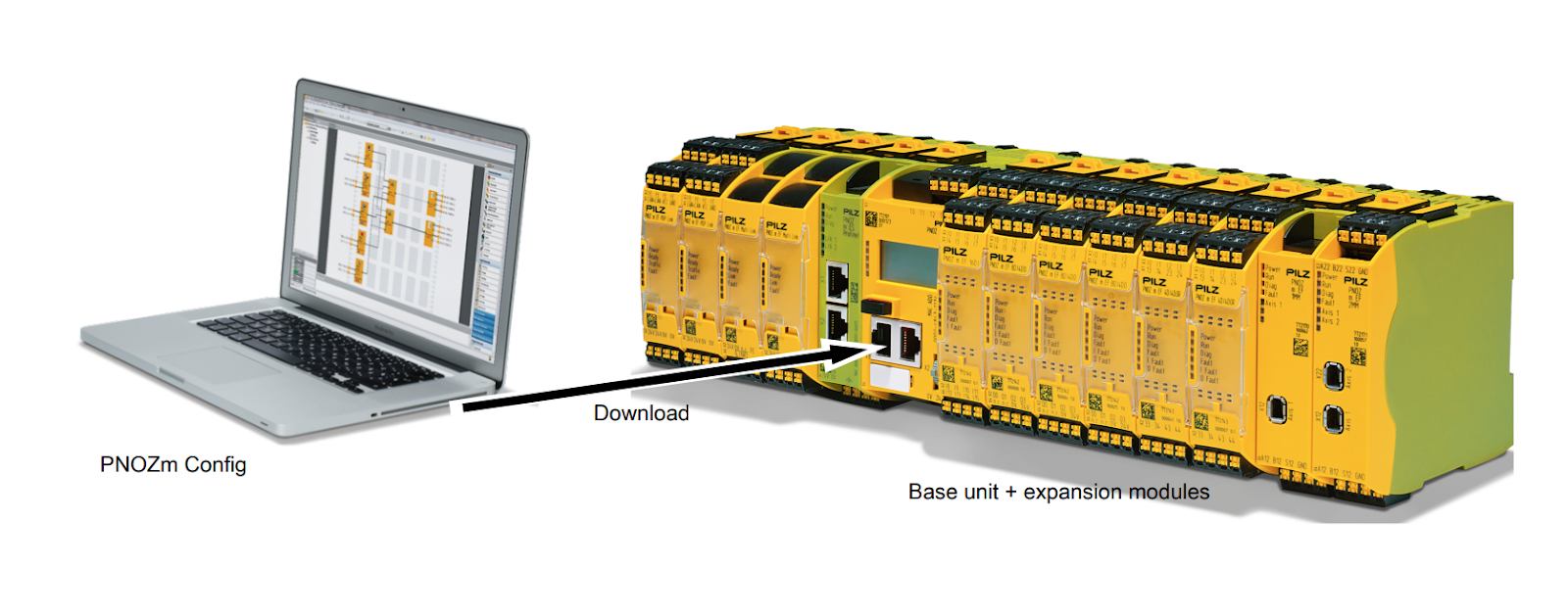
Structure of the configurable control system
設定可能なPNOZmulti 2の制御システムは、ベースユニットと拡張モジュールで構成されています。
ユニットのタイプによって、ベースユニットには以下のものがあります。
- 入力
- リレー出力
- 安全なsemiconductor出力
- 標準アプリケーション用出力
入力と出力の数は、拡張モジュールを使っていつでも増やすことができます。 モジュールはジャンパーでリンクされ、システム自体はPNOZmulti Configuratorで設定します。 特別な拡張モジュールにより、フィールドバス(非安全関連)または安全速度監視を介してデータを交換することができます。
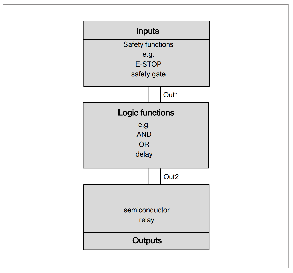
Operation of the units
PNOZmulti Configurator generates project files that are downloaded to the base unit:
- Safety functions performed by inputs (e.g., E-STOP monitoring, safety gate monitoring, etc.)
- How to connect inputs and outputs with logic functions
- Regardless of which output is set (semiconductor or relay) the unit will respond the same regardless of these functions.
- A high signal is output on output “Out1” when the activation conditions for a specific safety function are met.
- Output signals can be linked by logic functions and are output as “Out2” signals to the output of the PNOZmulti 2 unit.
Safety functions
Please note that the PNOZmulti 2 system has inputs and outputs that can be used for various safety functions, but may require special base units and modules.
- E-STOP push button
- Operating mode selection switch
- Switch activation
- Two-Hand Push Buttons
- Safety gate
- Light Curtains
- Light Barrier
- Muting
- Pressure sensitive mat
- Analog input signal
- Drives (e.g. monitoring of speed/speed range, direction of travel, operation stop)
- Furnace (base unit PNOZ m B1 burner module)
- Selection and authentication of operating modes via PITreader
System reaction times
The reaction time from the time an input is turned off to the time a linked output in the system is turned off depends on the delay time of the input, the delay time of the output, and the processing time. It is important to note that this time depends on which inputs and outputs are used by which device.

Calculation of the max. reaction time:
The formula for max. reaction time is as follows
| t ReactionMax = t Max input delay + t Max processing time. + t Max switch-off delay at the output |
It is important to note that the following factors may increase the reaction time.
- User-programmed delay time
- Delay time for sensors used
- Delay time of actuator used
- Maximum reaction time of base unit and expansion modules
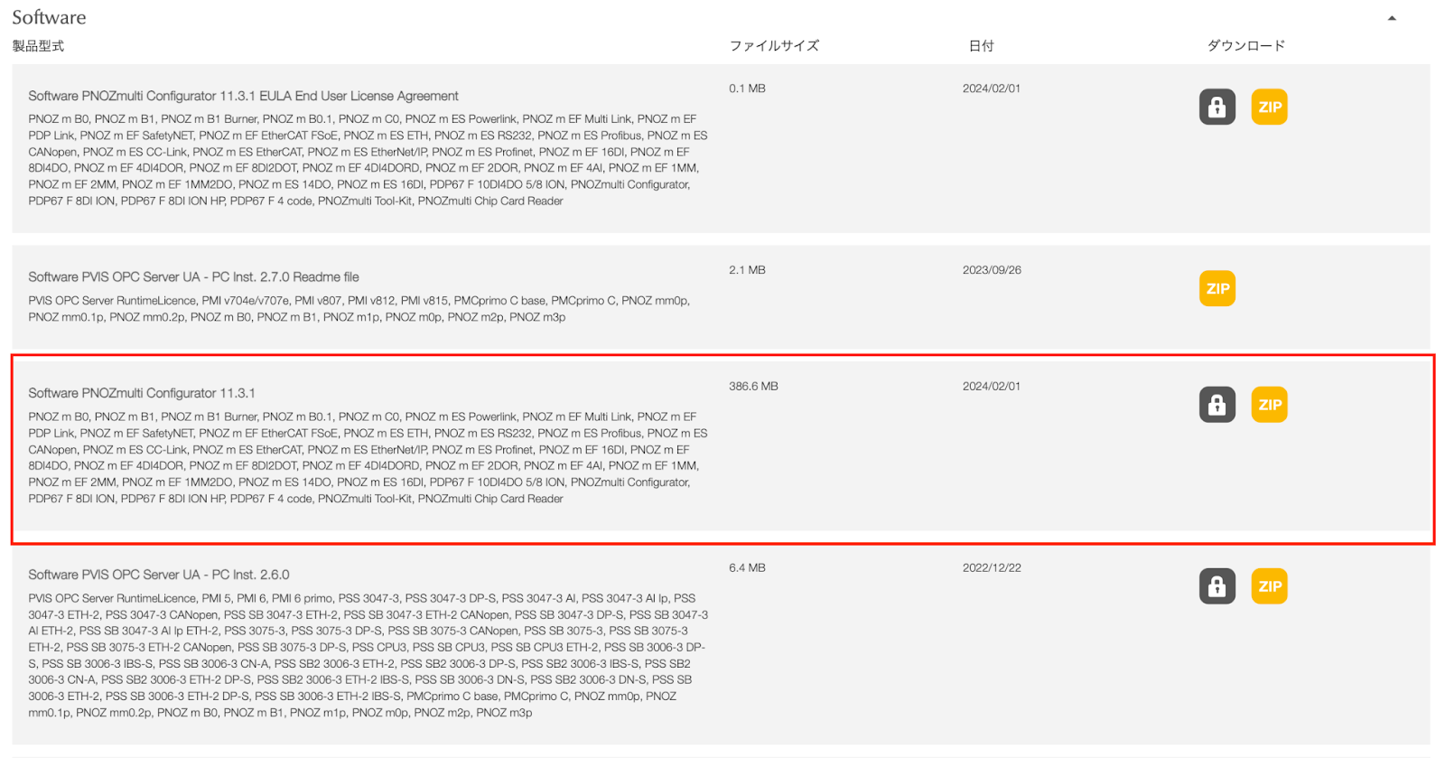
Tools Download
To build the PNOZmulti 2 Project, We need to use the PNOZmulti Configurator tool.
Download the latest version of the tool at the link below.
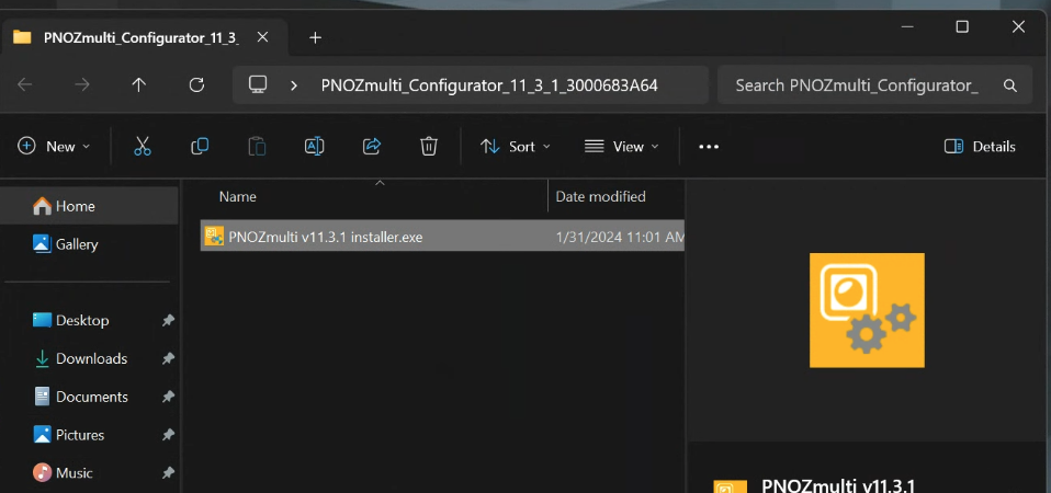
Tools Installaton
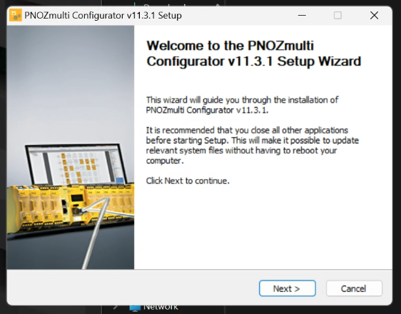
Double-click the setup file downloaded from Pilz HP to start installation.
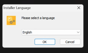
Select the tool installation language and proceed with OK.
Proceed with Next>.
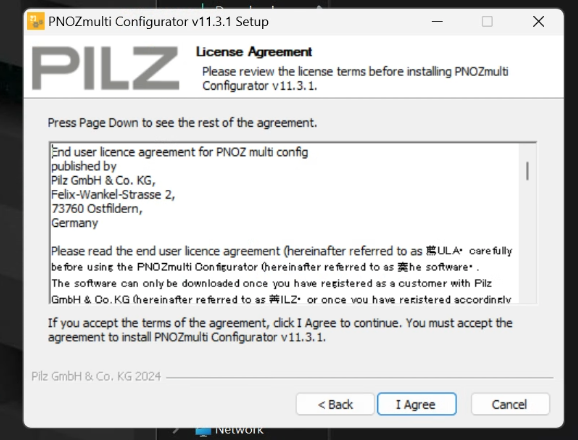
Agree to the license and proceed with the installation.
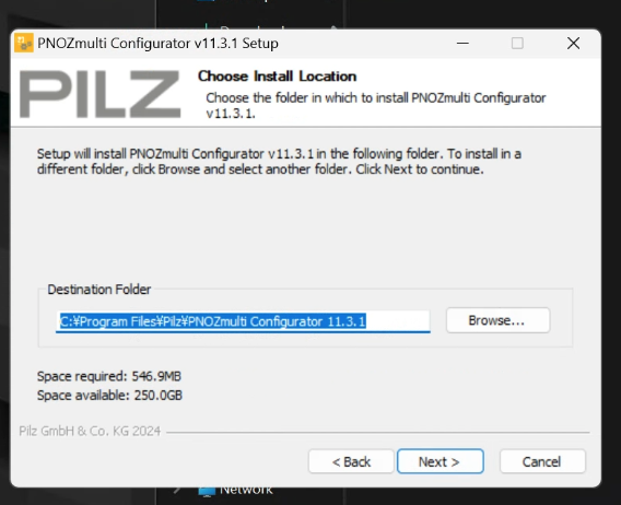
Select the Install destination for the tool and press Next> to proceed.
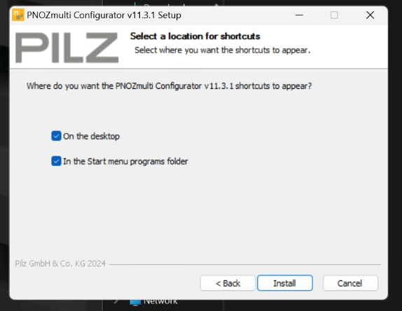
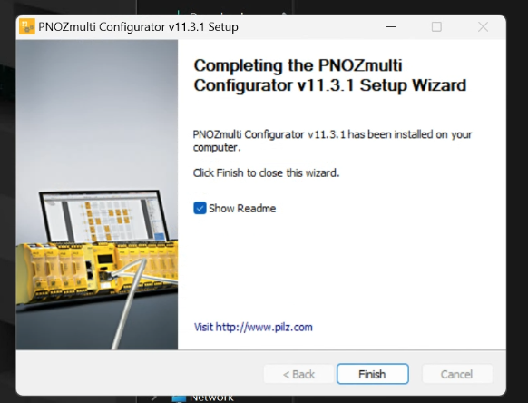
Create ShortCut, etc. and begin Install.
Just a second..
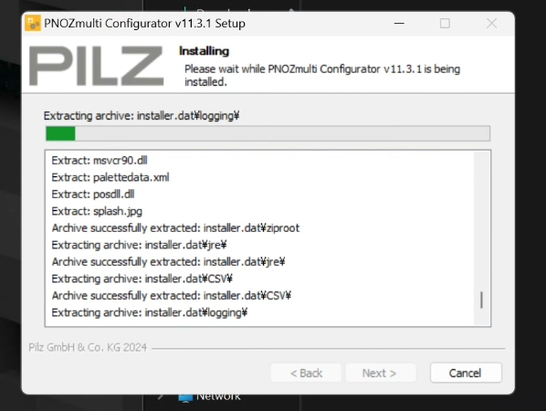
Done!
Configure
First, let’s set the IP address of the PNOZmulti 2 unit.
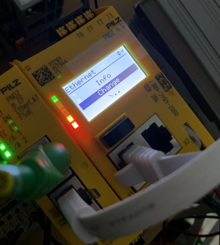
The Menu screen appears.
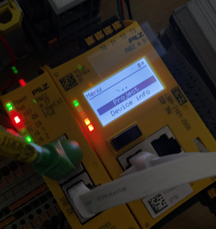
Pressing the rotary switch up or down changes the displayed item.
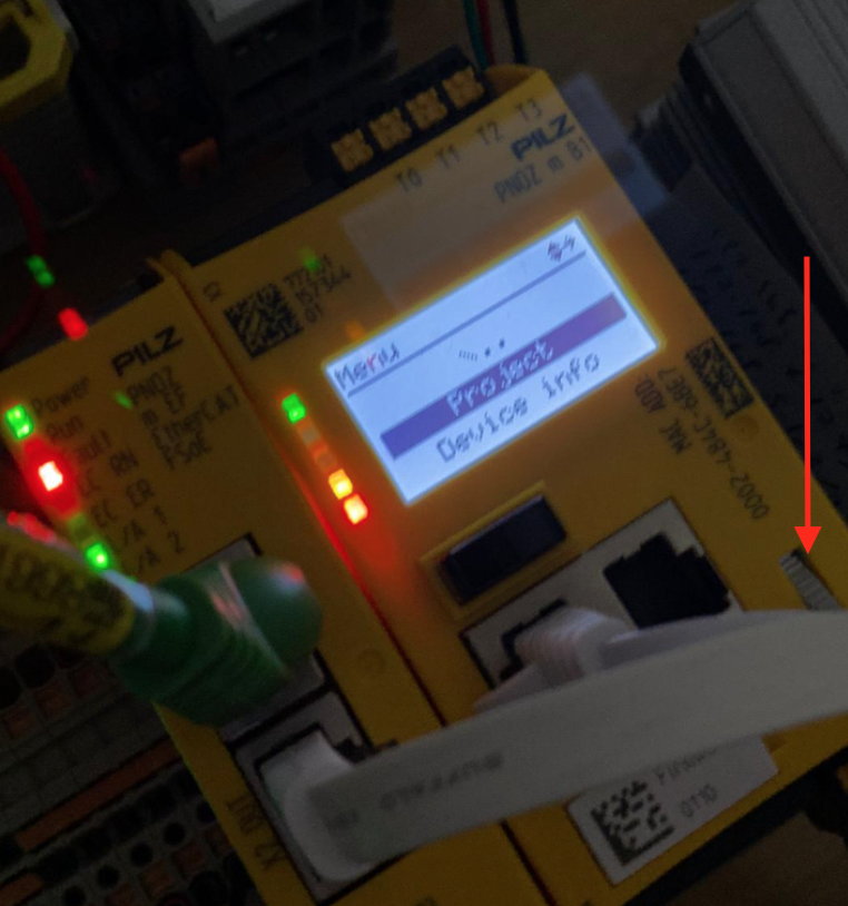
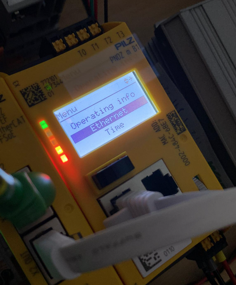
Select the Ethernet item.
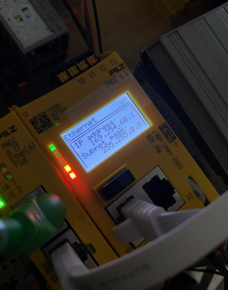
Info allows you to check the Controller’s IP address and other information.
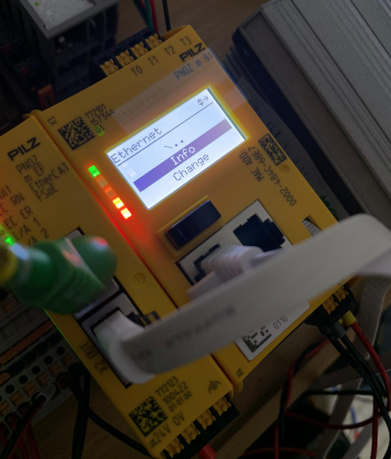
On Default, the IP address is unconfigured.
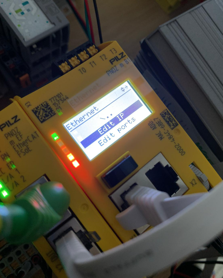
Select Change to change the IP address of the current CPU.
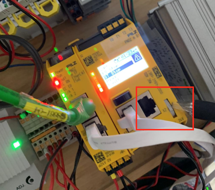
Click Edit IP.
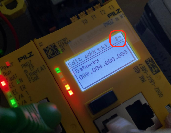
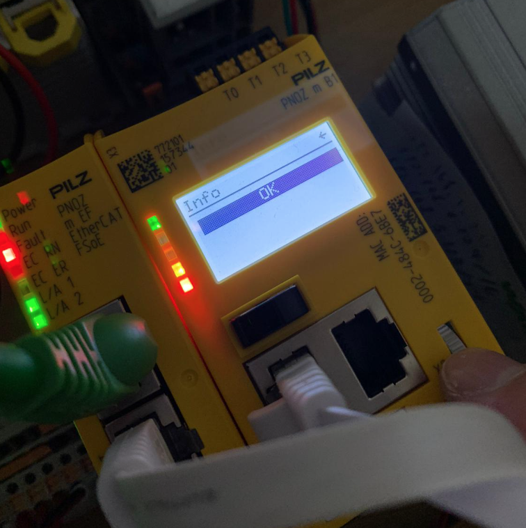
When a number is displayed on the CPU screen, the number appears in the red frame, and I have to press and hold it to enter the corresponding screen.
下記の動画で操作確認をすることができます。
Pilz.Open PNOZmulti 2 ‘s Configure Menu – YouTube
Done!The Address setup screen is now in.
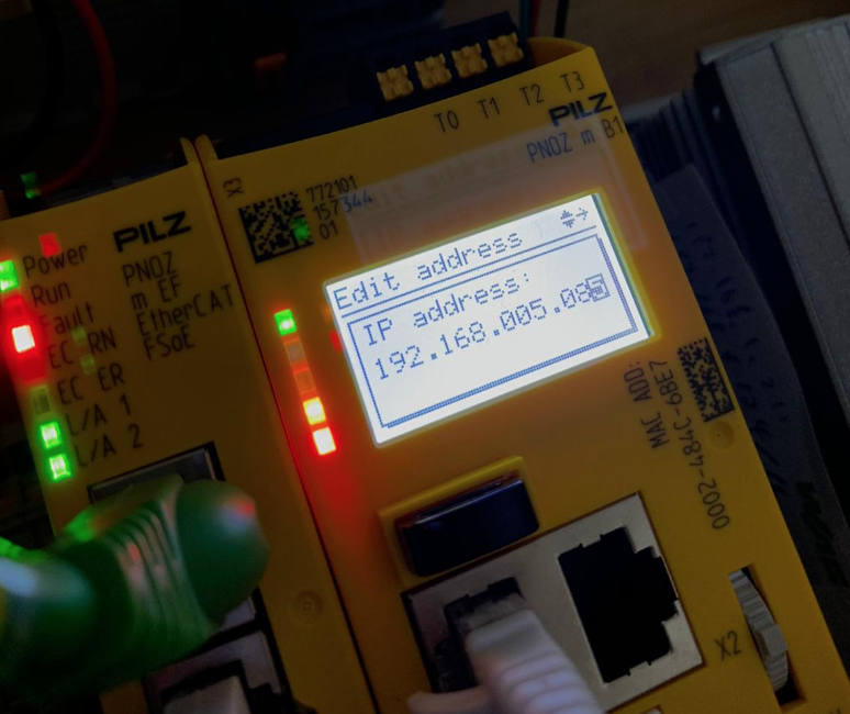
Set IP, Subnet, Gateway, etc. according to the application.
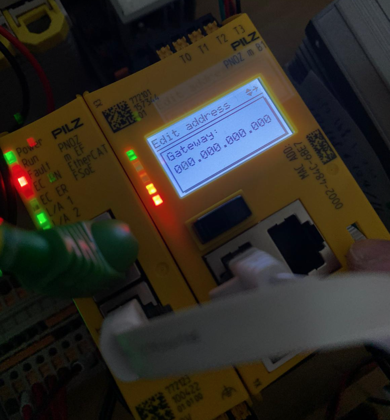
Done!
Your First Application!
You will have created a PNOZmulti Configurator Short Cut on your Desktop, so start PNOZmulti Configurator!
Just a second..
Done!
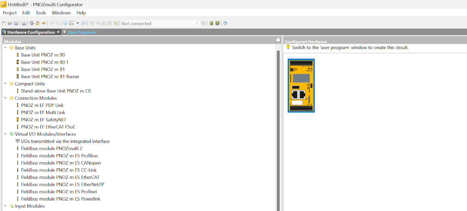
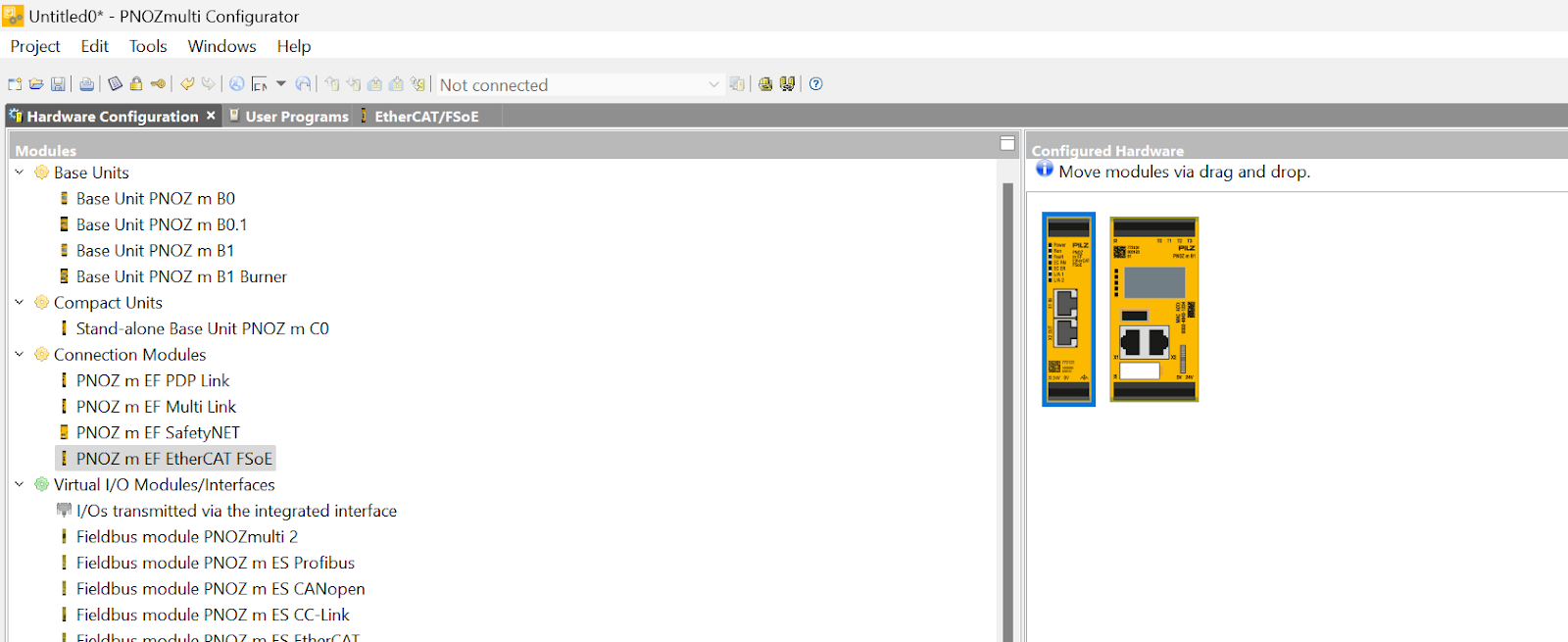
Add CPU
Add the CPU (Base Uint PNOZ m B1) used in this article.
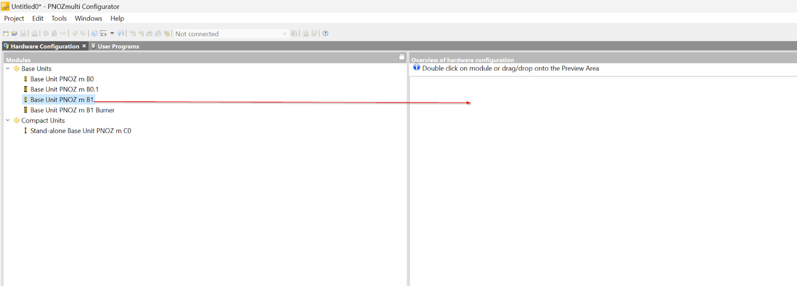
Done!
Add FSOE Module
Add PNOZ m EF EtherCAT FSoE to your project, although it will not be used in this article.
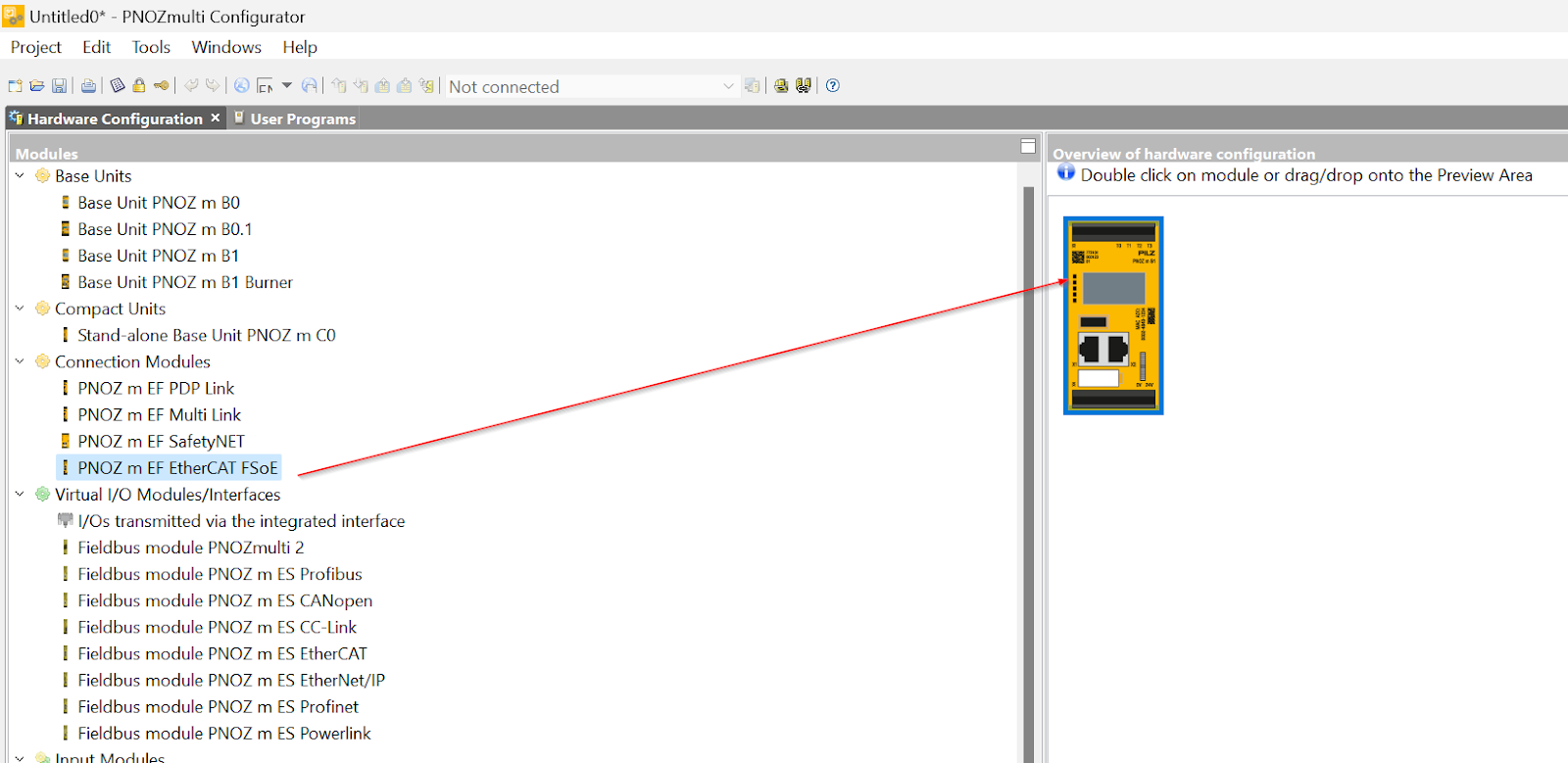
Done!
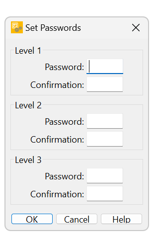
Setup Password
PNOZmulti Configurator may require a setup for Password. 3 levels can be set depending on the User’s operating permissions.
- level 1
Open the saved project and make all editing functions available. - level 2
You cannot open a saved project and make changes to the project. Projects can only be viewed. - level 3
Individual special functions can be set (refer to the instruction manual for details).
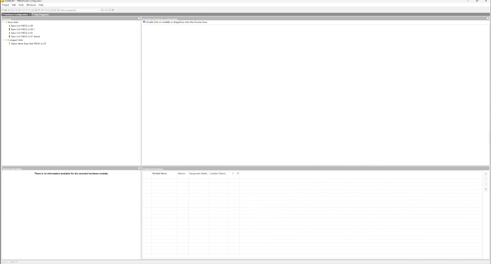
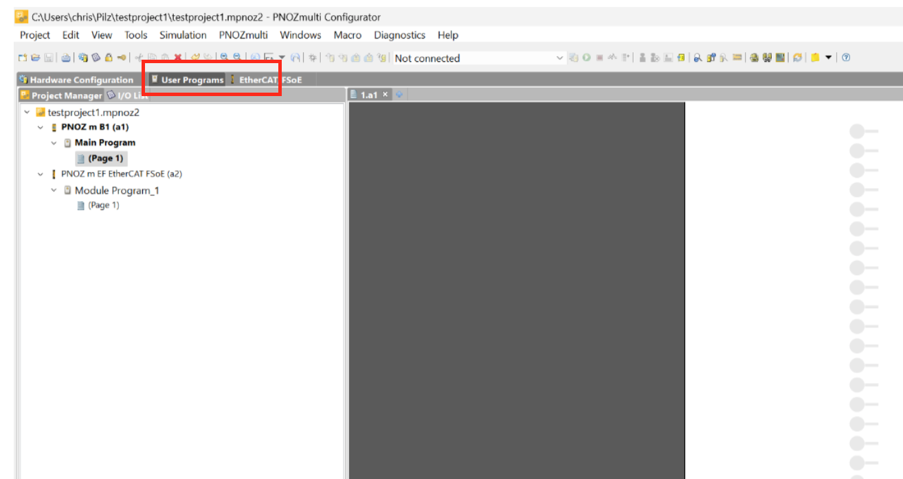
User Program
Click on the User Program tab to build a safety program.
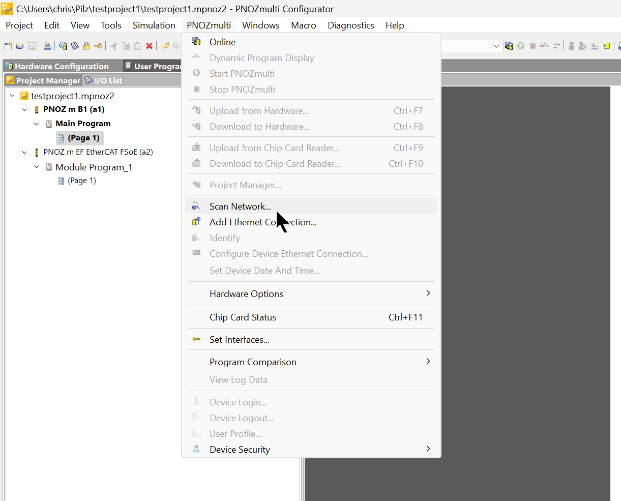
Scan Network
Click PNOZmulit>Scan Network to detect the PNOZmulti 2 currently on the network.
Select Base Unit PHOZ m B1 for Base unit Type and set the IP address range to search.
Then select the searched CPU.
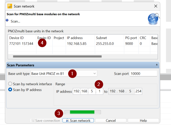
Done!
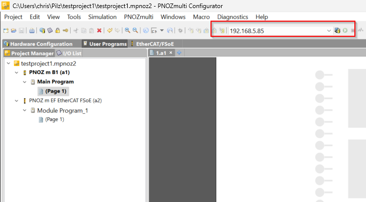
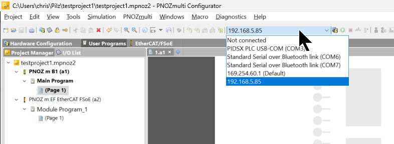
下記のDrop-Listで接続したいInterfaceを変更できます。
Online
Click PNOZmulit>Online to connect to the CPU.
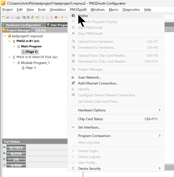
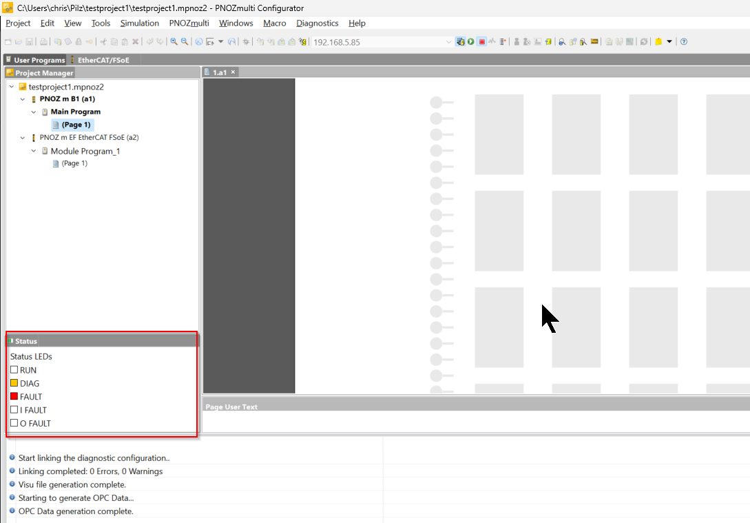
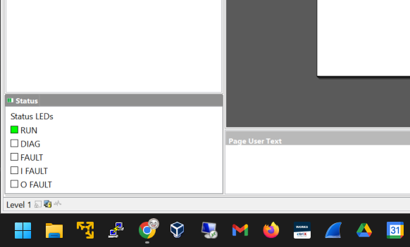
Done! The tool is now connected to the CPU, so the CPU’s operating status and other information is displayed.
View Error Message
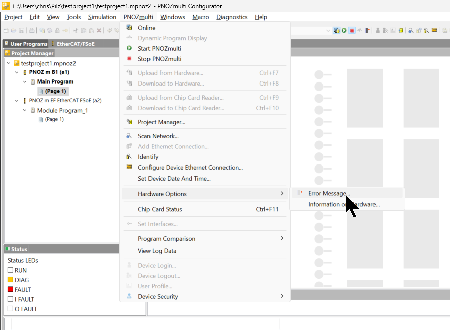
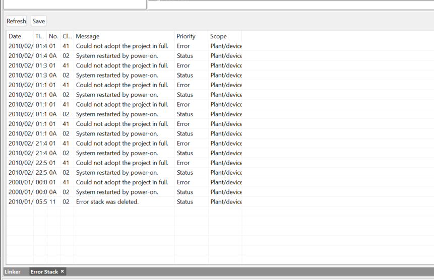
Click PNOZmulit>Hardware Options>Error Message to see the CPU error messages.
Done!
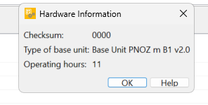
View Hardware Information
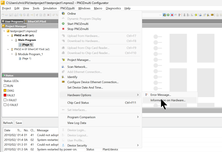
To check the firmware and operating hours of the CPU itself, click PNOZmulit>Hardware Options>Information Hardware.
Done!
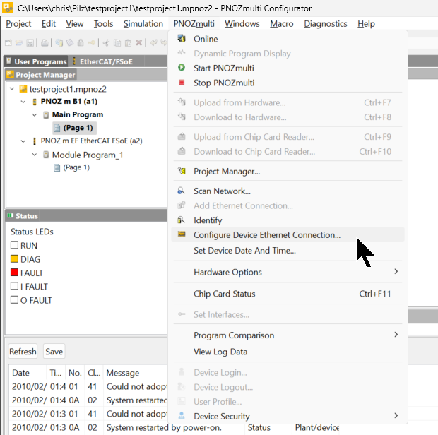
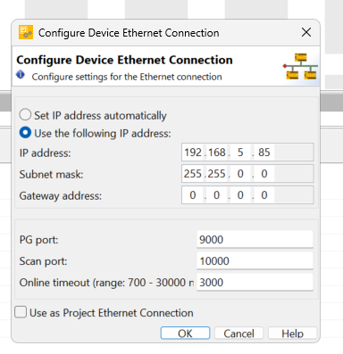
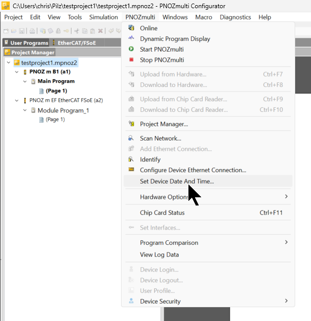
Configure Device Ethernet Connection
If you want to set the IP address of the CPU, click PNOZmulit>Configutre Devie Ethernet Connection.
Set the IP address, etc. according to the application.
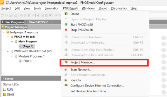
Download
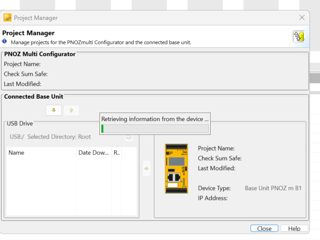
To Download a project, click PNOZmulit>Project Manager.
The Download screen appears.
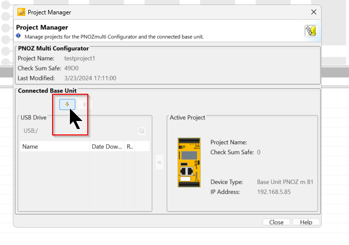
Click the button in the red frame to download the project.
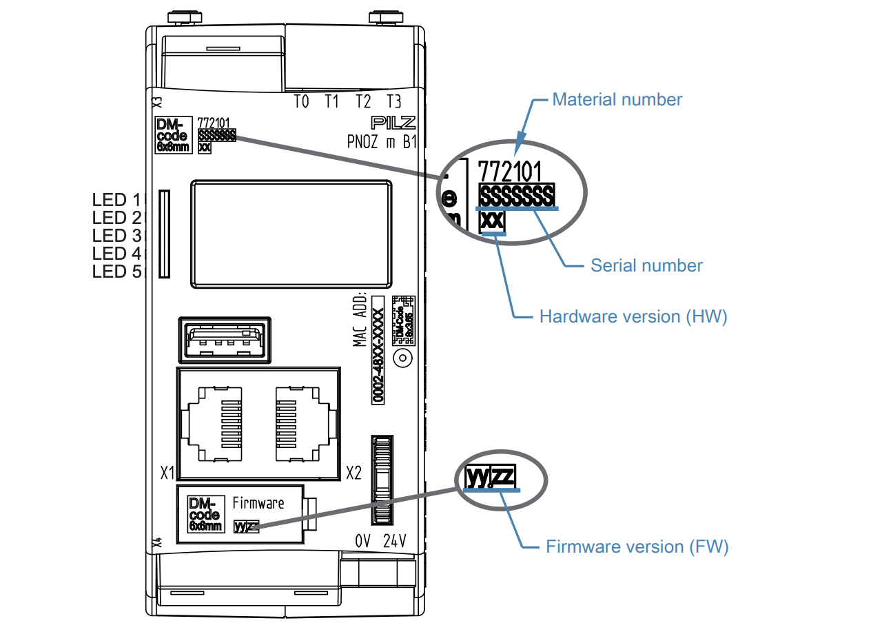
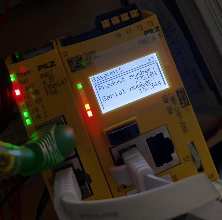
Enter the Order Number and Serial Number of the CPU.
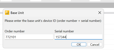
Order Number and Serial Number can be checked from the CPU screen.
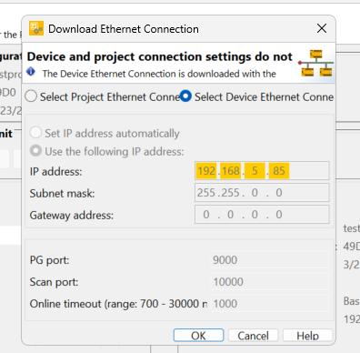
To change the Ethernet Connection, click “Select Device Ethernet Connection” and press OK to proceed.
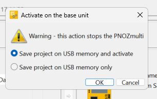
Select “Save project on USB Memory and activate” and press Ok to proceed.
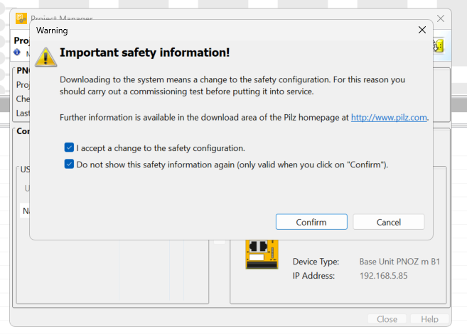
Check the notes and proceed with Confirm.
Please wait a moment as the Download starts.
The “Do you want to restart the PNOZmulti CPU from the tool? confirmation screen will appear, and proceed with Yes.
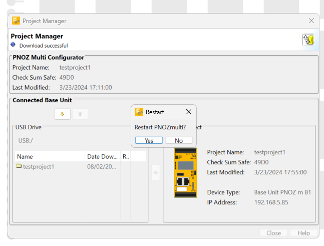
Done!The CPU is now in RUN Mode.
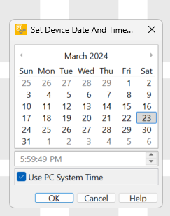
Set Device Data And Time
Finally, let’s set the CPU time: click PNOZmulti>Set Device Data And Time.
The Device time setting screen appears.
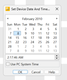
You can change the time by putting in the Checkbox for Use PC System Time and clicking Ok.