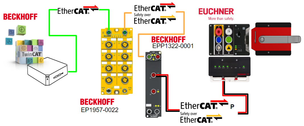
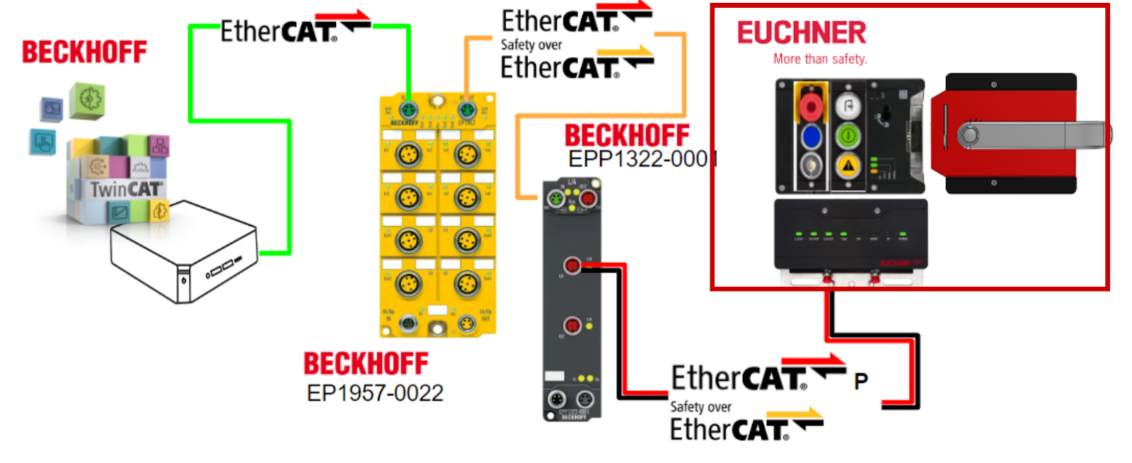
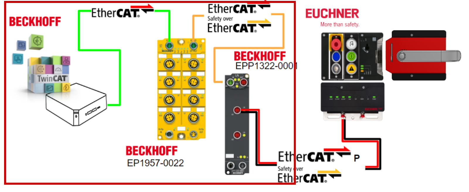
In this article, we will explain the procedure for setting up an EtherCATP and FSoE network from scratch.The EtherCAP is done with Beckhoff’s EPP1322-0001 Junction Box and the FSoE slave is done with Euchner’s Door Lock.
Come on, let’s enjoy FA.
Reference Link
Reference Video
Beckhoff.Let’s use FSoE and EtherCAT P with Euchnier Door Lock!
Foreword
Thank you from the bottom of my heart for visiting my technical blog and YouTube channel.
We are currently running the “Takahashi Chris” radio show with Full-san (full@桜 八重 (@fulhause) / X) which I deliver every Wednesday night.
Currently, our activities continue almost free of charge, and your warm support is very important for us to provide more content.If you are able, we would be very happy if you could support us by clicking on the links below.
Membership of Takahashi Chris
You can sign up for a membership to the radio we are doing with MR.Full (full@桜 八重 (@fulhause) / X from here.
https://note.com/fulhause/membership/join
AMAZON Gift List
This will be of great use to me in creating content for my blog and improving my facilities.
https://www.amazon.co.jp/hz/wishlist/ls/H7W3RRD7C5QG?ref_=wl_share
Patreon
Here is a small Patreon of support for the creation of content and equipment for my blog.
https://www.patreon.com/user?u=84249391
Your support will help us to enhance our activities.
Thank you in advance for your support.
Email Address(*=@)
X
EtherCATP?
EtherCATP is a one cable solution that brings us one step closer to automation without the need for a control cabinet, and allows Beckhoff to integrate communication and power into a single 4-wire standard Ethernet cable.

The 24 VDC power supply for the EtherCAT P slave and the connected sensors and actuators is integrated:
- US (system and sensor supply)
- UP (actuator peripheral voltage)
They are electrically isolated from each other and can each supply up to 3 A of current to the connected components.
At the same time, all EtherCAT advantages such as topology design freedom, high speed, optimal bandwidth utilization, on-the-fly telegram processing, high-precision synchronization, and extensive diagnostic capabilities are retained.
The US and UP currents are coupled directly to the wires of the 100 Mbit/s line, resulting in a highly cost-efficient and compact connection. EtherCAT P offers advantages both for small remote I/O stations in terminal boxes and for connecting distributed I/O components in the process.
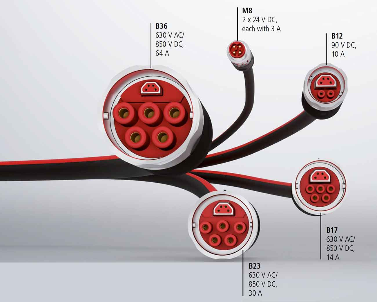
There is a family of connectors specifically developed for EtherCAT P to prevent potential damage due to misconnections with standard EtherCAT slaves, covering all applications from the 24 V I/O level to drives with 630 V AC or 850 V DC and currents up to 72 A.
- All sizes have the same design for easy installation.
- Preconfigured cables reduce assembly time
- Colored wires and identification in connectors (red and black)
- Poka-yoke principle for each component
- Flange sockets with industry standard flange dimensions (front assembly, rear assembly, square flange)
The EtherCAT P element also allows for high-density mounting and increases the current-carrying capacity and isolation voltage of the power supply pins.
- Seamless and consistent 360° shielding of connectors
- Uniform EtherCAT P-elements in all sizes B12 to B40
- Uniform construction in all sizes B12 to B40
- Bayonet connectors for quick connection and disconnection
- Shielded and unshielded (outer shield) variants available
- Various pin and socket combinations
- Mechanical keying (2- to 6-position mechanical keying available, depending on size and number of poles)
- Marking by color ring available
- Thinner cables can be made by reducing the number of wires per cable connector.
This can be significantly less expensive than adopting EtherCAT P.
- Optimized for direct connection of EtherCAT P devices in the field
- Time savings due to reduced wiring effort
- Fewer errors
- Miniaturization of sensors and actuators by eliminating the need for separate supply cables
- Simple connection of components
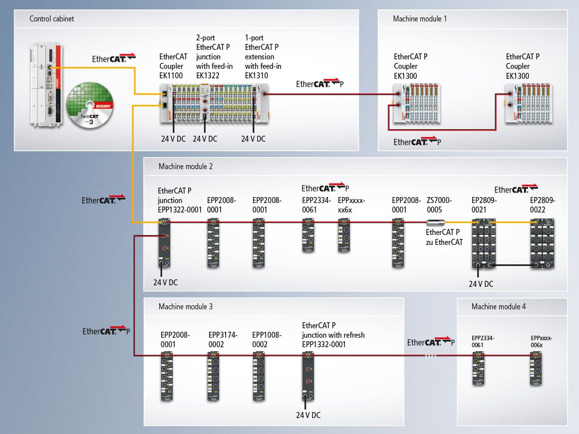
EtherCAT typically offers a choice of topologies, combining line, star and tree structures to achieve the best system layout at the lowest cost.Unlike conventional PoE (Power over Ethernet), EtherCAT P allows devices to be cascaded and powered from a single power supply unit.
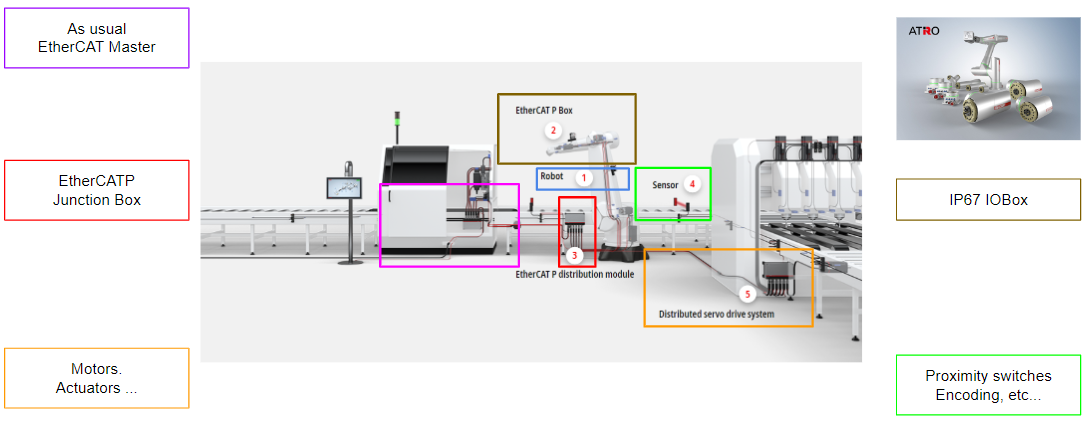
When designing a machine, the individual consumers, cable lengths, and cable types are configured in the tool and this information is used to create the optimal layout of the EtherCAT P network.Since it is known which sensors and actuators will be connected and which sensors and actuators will operate simultaneously, power consumption can be properly calculated.For example, if two actuators do not switch at the same time from a logical point of view, they do not require the full load at the same time.As a result, the required power supply and power could be further saved.
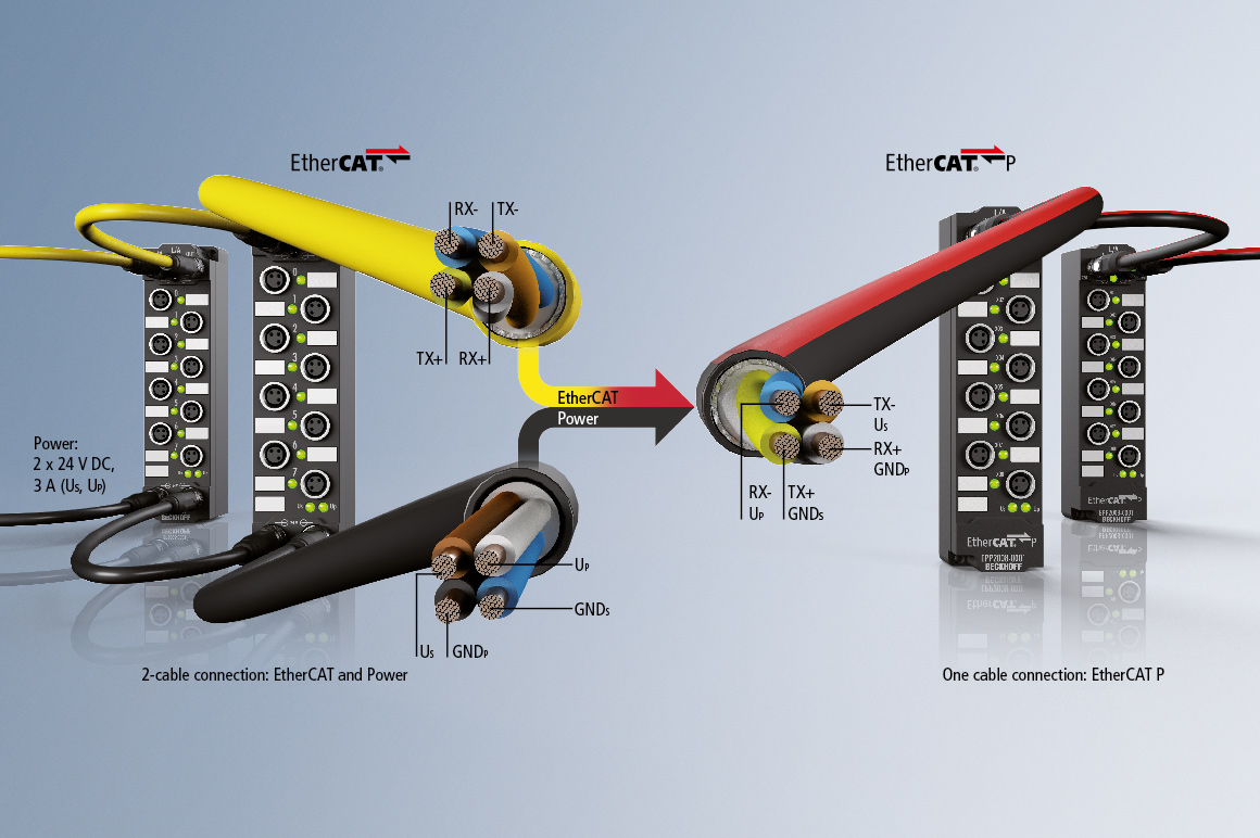
With EtherCAT P, Beckhoff integrates communication and power on a single 4-wire standard Ethernet cable.
The 24 VDC power supply for the EtherCAT P slave and the connected sensors and actuators is integrated: US(system and sensor power) and UP (peripheral voltage for actuators) are electrically isolated from each other and can each supply up to 3 A of current to the connected components.
At the same time, all EtherCAT advantages such as topology design freedom, high speed, optimal bandwidth utilization, on-the-fly telegram processing, high-precision synchronization, and extensive diagnostic capabilities are retained.
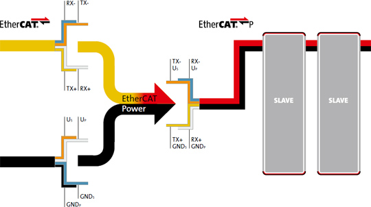
The US and UP currents are coupled directly to the wires of the 100 Mbit/s line, resulting in a highly cost-efficient and compact connection. EtherCAT P offers advantages both for small remote I/O stations in terminal boxes and for connecting distributed I/O components in the process.To prevent potential damage due to misconnections with standard EtherCAT slaves, a family of connectors has been specially developed for EtherCAT P. It covers all applications from the 24 V I/O level to drives with 630 V AC or 850 V DC and currents up to 72 A.
- Optimized for direct connection of EtherCAT P devices in the field
- Time savings due to reduced wiring effort
- Fewer sensor and actuator errors due to elimination of individual supply cables
- Simple connection of components
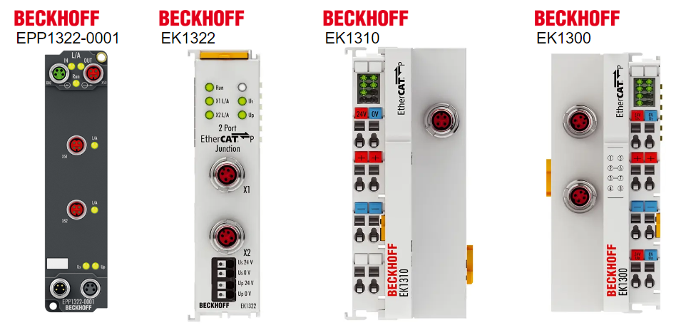
EPP1322-0001?
The EPP1322-0001 EtherCAT P junctions in IP67 allow flexible topology configuration and with a current carrying capacity of 3 A per EtherCAT P segment in US and UP, a wide range of sensors and actuators can already be used.
The EPP1332-0001 EtherCAT P junction with refresh function can also be used to feed US or UP at any point in the system.
EPP1342-0001 is used for topological branches that do not require a voltage boost.All InfraBox modules have EtherCAT, US, and UP status LEDs.
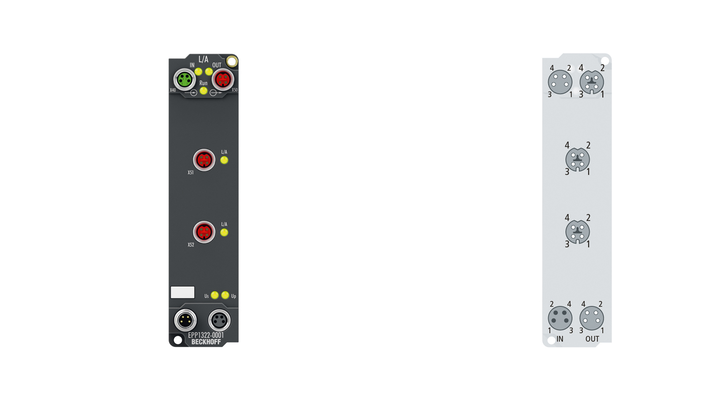
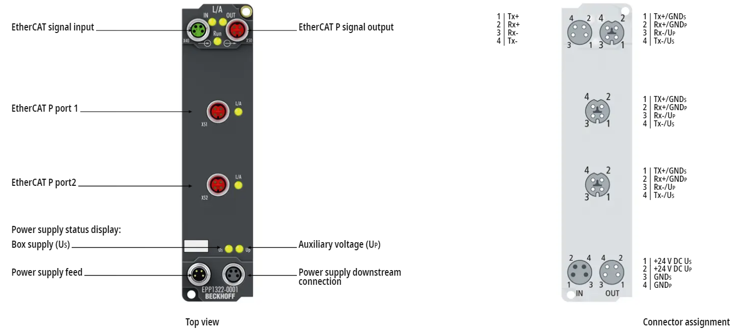
Layout
This is Layout for EPP1322-0001.
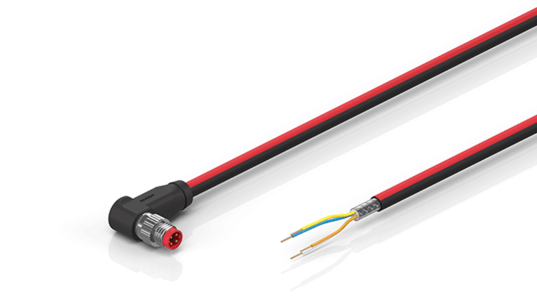
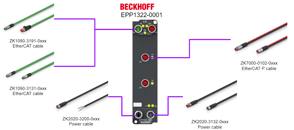
Cables
Here is an example of the cables required to use the EPP1322-0001 module.Please contact Beckhoff for more information.
Blocks
Here is the internal Block diagram of EPP1322-0001.
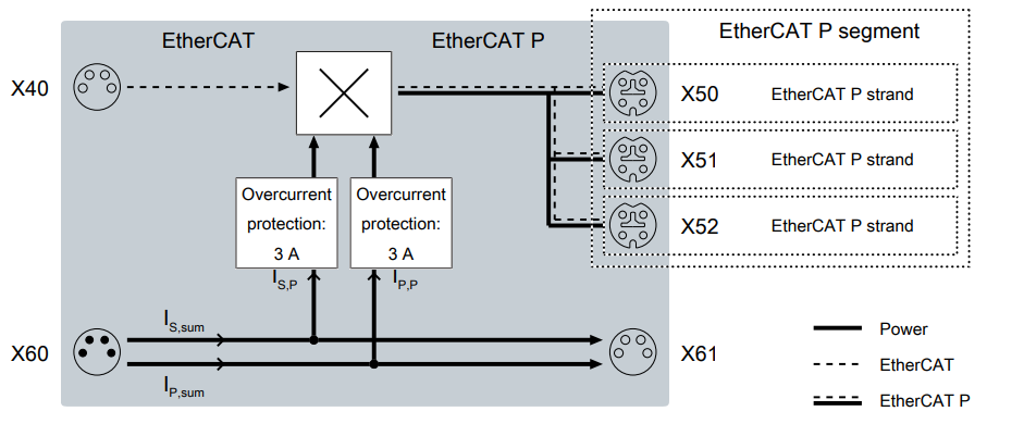
If short-circuit shutdown..
If a short circuit is detected at EtherCAT P output X50, the affected output voltage is automatically turned off.The output voltage will remain off until a voltage reset of the corresponding supply voltage is performed.
Note that if you want to turn on a switched-off output voltage again without voltage reset, use EP9224-0037 instead of EPP132x. With EP9224-0037, the switched-off voltage can be turned on again by software.
Not Just EPP1322-0001!
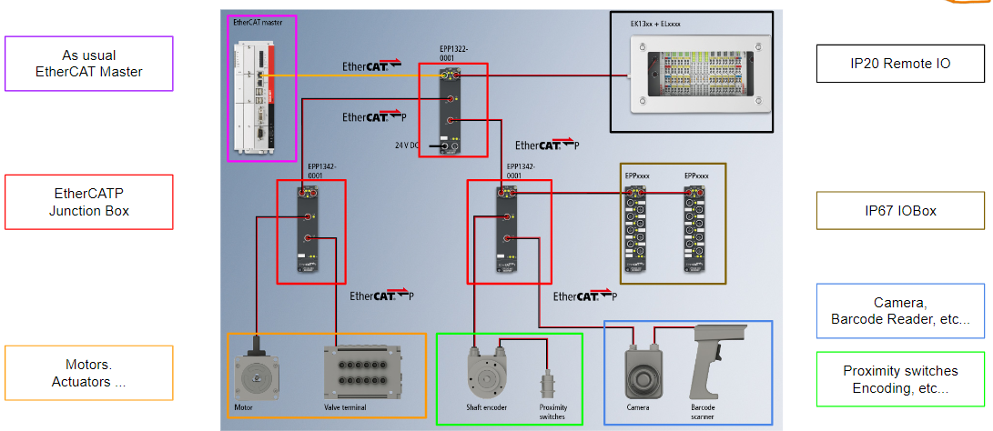
EtherCAT typically offers a choice of topologies, combining line, star and tree structures to achieve the best system layout at the lowest cost.Unlike conventional PoE (Power over Ethernet), EtherCAT P allows devices to be cascaded and powered from a single power supply unit.
The EK13xx EtherCAT P couplers with IP 20 rating also enable the use of EtherCAT P from the control cabinet to the machine:
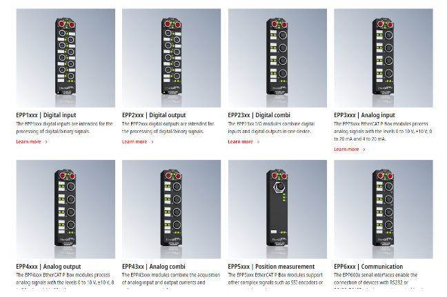
The EPPxxxx EtherCAT P-box modules with protection class IP 67 can cover the typical requirement range of I/O signals.
- Digital input (3.0 ms or 10 μs filter)
- Digital output (output current 0.5 A)
- Combination module with digital input and digital output
- Analog input/output with 16-bit resolution
- Thermocouple and RTD inputs
Euchner Door Lock..
The FSoE Slave used in this article is an EtherCATP-compliant type from Euchner.
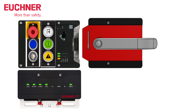
In addition, Euchner door locks can be freely combined depending on the application.
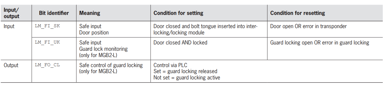
Function
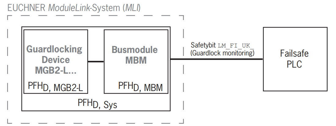
Monitoring of guard locking and the position of the guard
Here is an example of the use of guard locks and guard position monitoring.
- If the guard lock is released, safety bit LM_I_UK (ÜK) = 0 (monitor locking element).
- If the guard is open, safety bit LM_I_SK (SK) = 0 (monitor guard position).
- Locking of the guard is only activated when the bolt tongue is in the locking module.
- It also prevents inadvertent locking (prevents false closure).
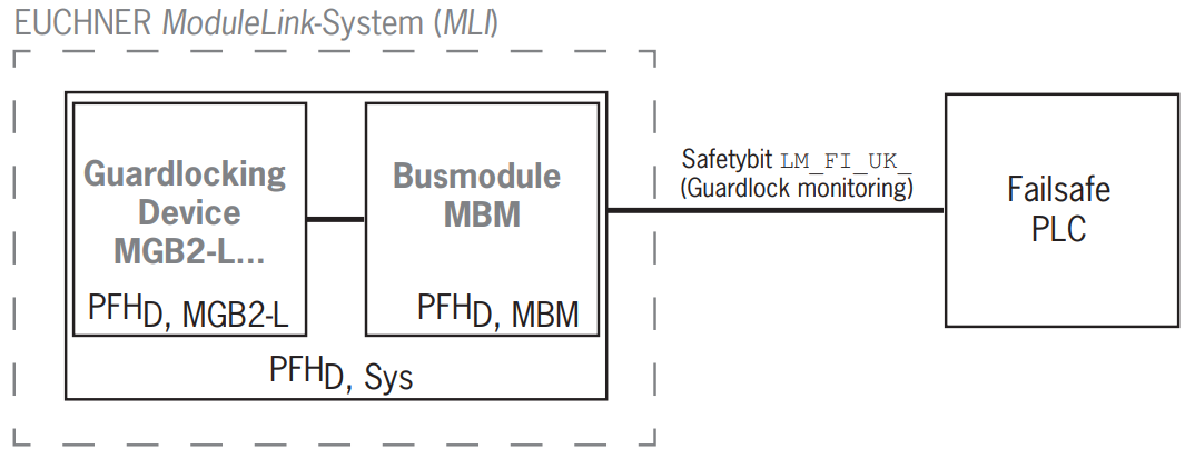
Control of guard locking
Here is an example of the use of GuardLock controls.
- If the guard lock is released, safety bit LM_I_UK (ÜK) = 0 (monitor locking element).
- If the guard is open, safety bit LM_I_SK (SK) = 0 (monitor guard position).
- Locking of the guard is only valid when the bolt tongue is in the locking module.
- It also prevents inadvertent locking (prevents false closure).
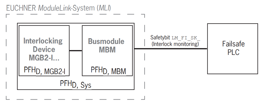
Monitoring of the guard position
Here is an example of the use of the control of guard position monitoring.
- When the guard is open, the safety bit LM_I_SK (SK) = 0.
Safety functions on submodules with emergency stop
Here is an example of the use of controlling the safety function of a submodule with emergency stop function.
- When the emergency stop is pressed, the safety bit SM_FI_ES = 0.

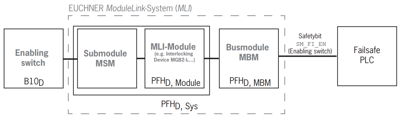
Safety functions on submodules with enabling switch
Here is an example of the use of a submodule with an enable switch to control safety functions.
- When the enable switch is pressed, the safety bit SM_FI_EN = 1.
Safety functions on submodules with safe pushbuttons and switches (general)
Here is an example of the use of safety pushbuttons and switches to control submodule safety functions.
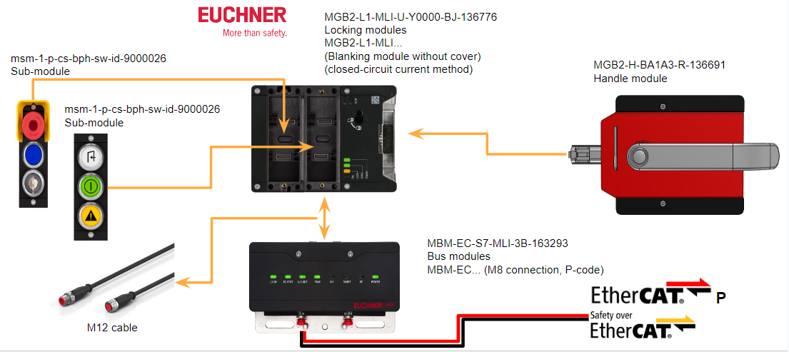
MBM-EC-..-MLI-… (EtherCAT)?
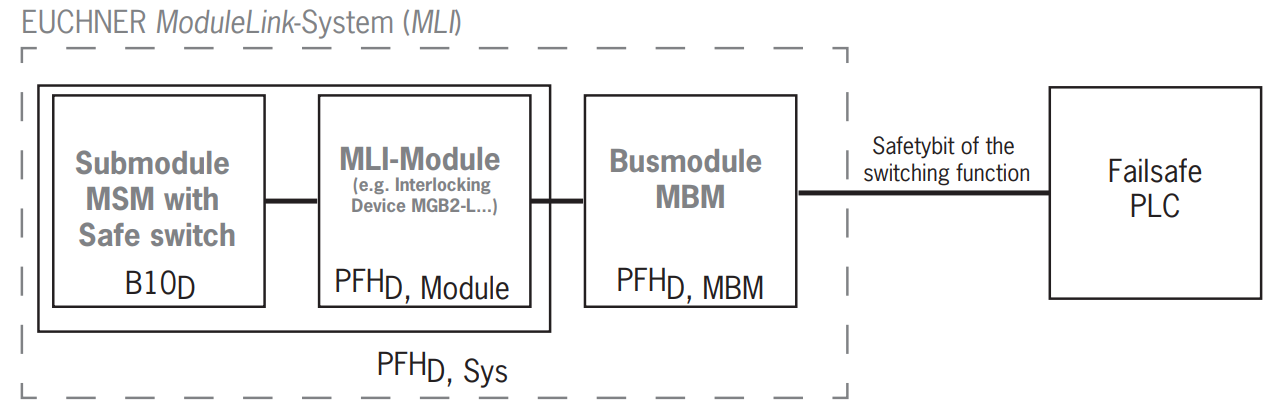
The safety function of the bus module MBM is to evaluate safety data sent from the overall system (e.g., installed guard locking devices, emergency stop devices, enabling switches, etc.) and transfer them onto the connected bus system.It should be noted that the number of safety devices in the system is limited to 12.

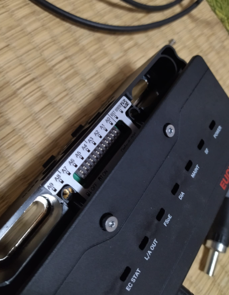
DIP
The DIP switches have the following functions
- Set FSoE slave address for device
- Hardware reset to restore device to factory settings
- Activate the device’s web interface
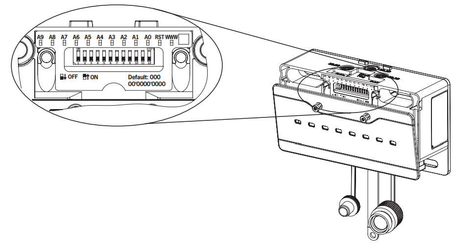
A0 … A9
A0…..A9 are bits 0 to 9 in the FSoS address switch.
(Factory default setting: 0000000000)
RST
Button for factory reset.
WWW
Switch to activate the device’s web interface with extended diagnostic options.
System layout and data areas
With its modular layout, the MLI system offers tremendous flexibility.This flexibility also applies to the use of communication data; the data area the system occupies within the control system depends on the system layout.
The following diagram is intended to clarify which rules must be used to combine data blocks of individual modules and submodules.It is important to note that a distinction is made between insecure EtherCAT data and secure FSoE data.
Each module has fixed communication data, which is permanently assigned when the modules are combined in the configuration software for the control system.Some modules and sub-modules also have optional data that can be evaluated.These also allow for more detailed diagnostic functions.
EtherCAT data is always incorporated in bytes (blocks #1 to #4), while FSoE data is always incorporated in individual bits (single bit in the figure below).This means that sufficient safety memory must be available for FSoE data.
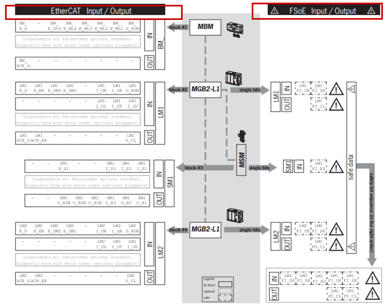
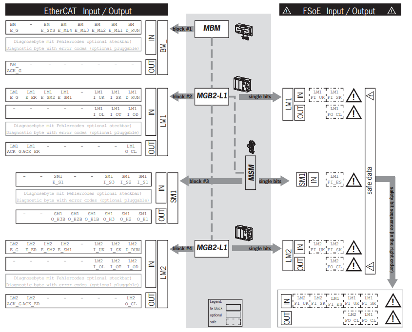
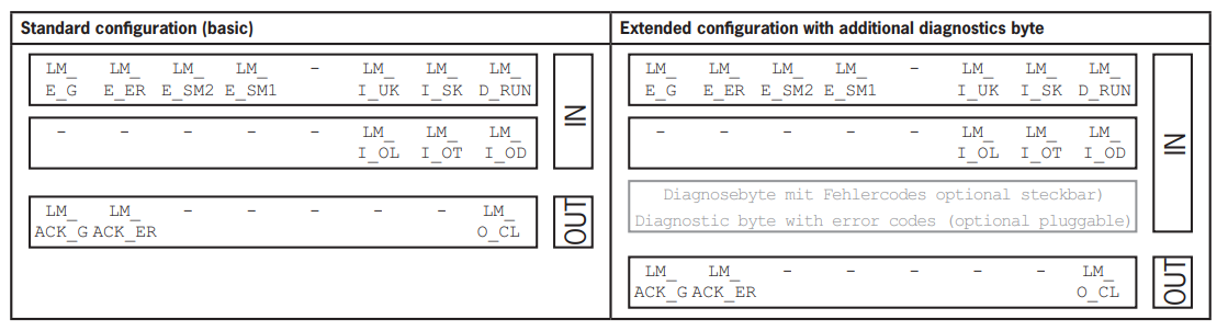
EtherCAT data bytes
Each module or sub-module of the EtherCAT network transmits specific non-safety communication data.Each module or submodule occupies a certain number of EtherCAT data bytes in the I/O area of the control system.
The following modules can exist in various combinations in an MLI system
- Bus Module MBM
- Multiple Interlocking/Locking Module MGB2-I or MGB2-L Expansion Module MCM
- Multiple sub-modules MSM
Some modules and submodules offer a choice between a standard configuration (basic) with basic status, signal, and control functions and an extended configuration with additional bytes, including accurate error codes for diagnostics.

FSoE data bytes
In addition to the insecure EtherCAT data, secure FSoE data are transmitted within the EtherCAT network.These data include all information about the locking position of interlocks and locking modules MGB2, emergency stop and enabling switches, bolt tangs and guards on the safety input X.
EtherCAT data is always embedded in bytes, whereas FSoE data is always embedded in individual bits.This means that sufficient safety memory must be available for FSoE data.
Euchner devices offer the following FSoE data blocks
- 2 input bytes and 2 output bytes
- 4 input bytes and 4 output bytes
- 8 input bytes and 8 output bytes

Watch dog
Watch dog parameters Update time and FSoE Watchdog Time have a decisive influence on the reaction time of the safety function, and it is important to note that if the reaction time is too long, the safety function may be lost.
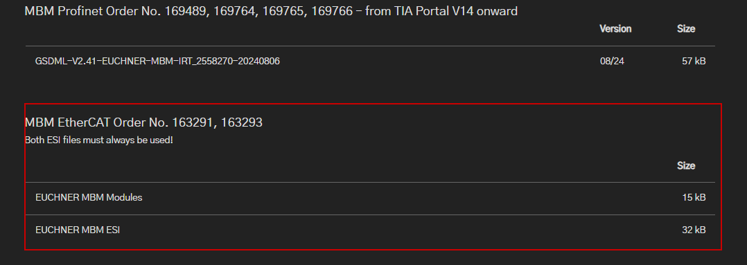
ESI File
To integrate Eucher’s EtherCAT devices into a control system, a corresponding ESI file in XML format is required.Be sure to use both ESI files as a precaution.
- EUCHNER_MBM_ESI.xml
- Contains all information about the MBM module and data transfer.
- EUCHNER_MBM_Modules.xml
- It contains a description of all modules connected to the MBM.
The ESI file must also be imported into the control system’s configuration software before the actual EtherCAT network can be set up.
Your Flow..
To integrate Eucher’s EtherCAT devices into a control system, the following workflow is required:
- Configure the system and set the parameters with the configuration software for the control system (in this case TwinCAT3 is used).
- The following EtherCAT parameters must be set
- Update Time
- FSoE address
- Watchdog time (time during which the control system expects a response from the FSoE device): [xxx ms]. Factory default from ESI file: [100 ms].
- Set the FSoE address of the bus module MBM with DIP switches.
- Link Safety Data with FSoE Master.
- Set additional parameters for individual modules, depending on the application
- Save the configuration and transfer it to the system.
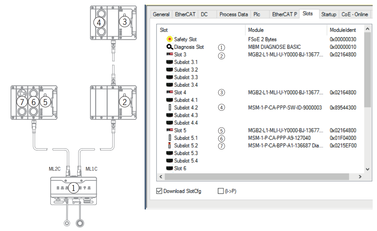
Also, when scanning the EtherCAT network, all modules and sub-modules that use basic diagnostics are slot-configured, and 8-byte modules are automatically entered in the safety slots.They must then be changed manually.
Line swap
At first startup, if the control system configuration matches the MLI topology, the current MLI topology is saved.But when the system is rebooted, the bus module will detect if the location of the MLI device changes and if the device is operating on a different MLI line.
The bus module further reports an error if a device is removed or added.This is intended to prevent accidentally connected devices from entering safe mode after maintenance work, for example.
If the system reports a line swap error, check the MLI topology and correct it if necessary; if the MLI topology again matches the saved topology, the system will again enter normal operation after reboot.
Any intentional changes to the MLI topology must be reset by a factory reset.
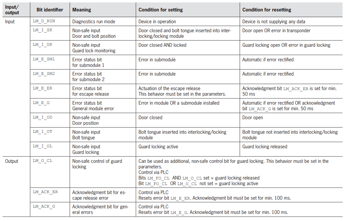
Safe bits
Here is the Mapping of FSoE safety data.
Non-Safety bit
Here is EtherCAT’s Mapping of M non-safety data.
Implementation
Euchner Side
The first step is to build from the Euchner side.
Download ESI File
Euchner’s ESI and other File downloads are available here.
https://www.euchner-usa.com/en-us/
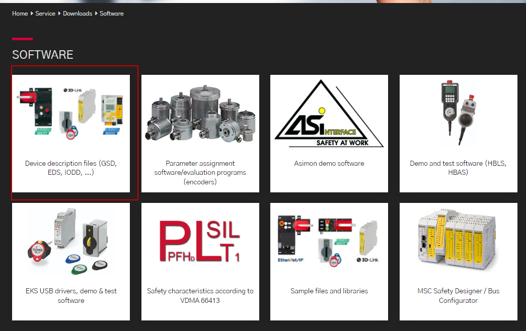
Click on SERVICE>Downloads.

Click on Software.

Device description Files.Click on “Device description Files…”.
Click on MGB2, which will be used in this article.
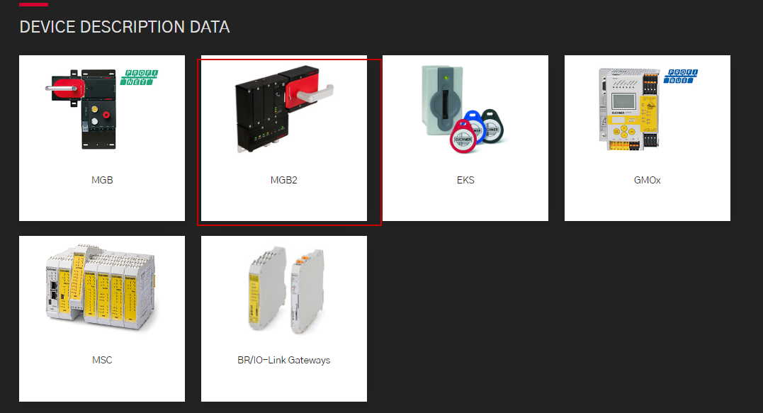
You can downlaod all of Euchner’s device File.
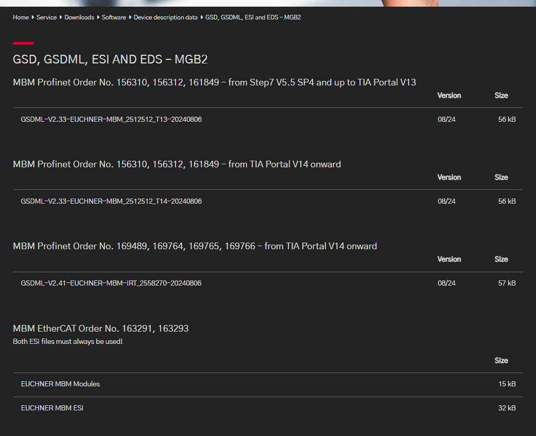
Finally, download the ESI File to your PC.
TwinCAT3 Side
The next step is to build the TwinCAT3 side.
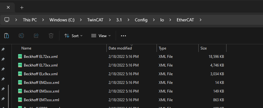
Install ESI File
Put the ESI File in the following Directory.
C:\TwinCAT\3.1\Config\Io\EtherCAT
Connect to TwinCAT Runtime
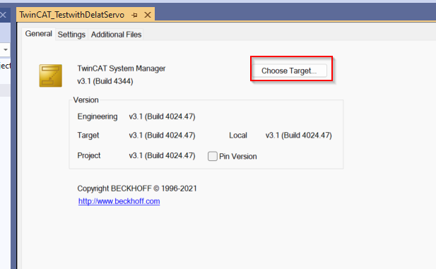
If TwinCAT Runtime is not local, you will need to set up a connection point and open SYSTEM.

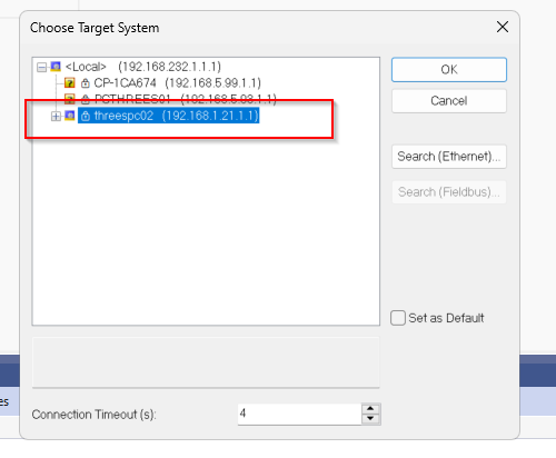
Click Choose Target.
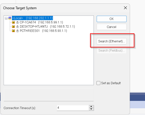
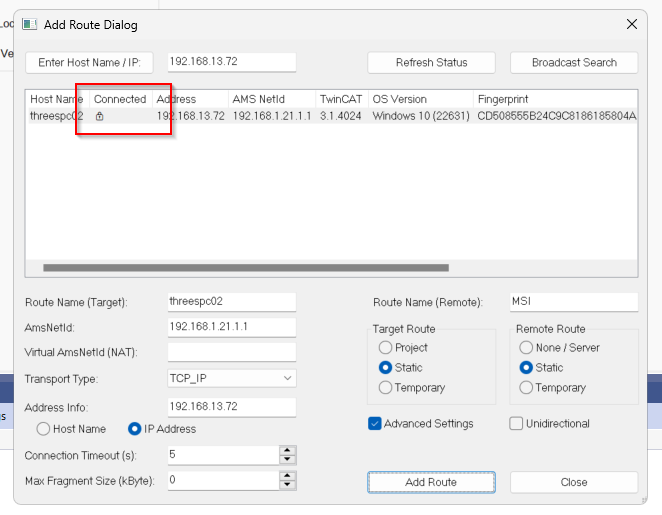
Click Search(Ethernet).
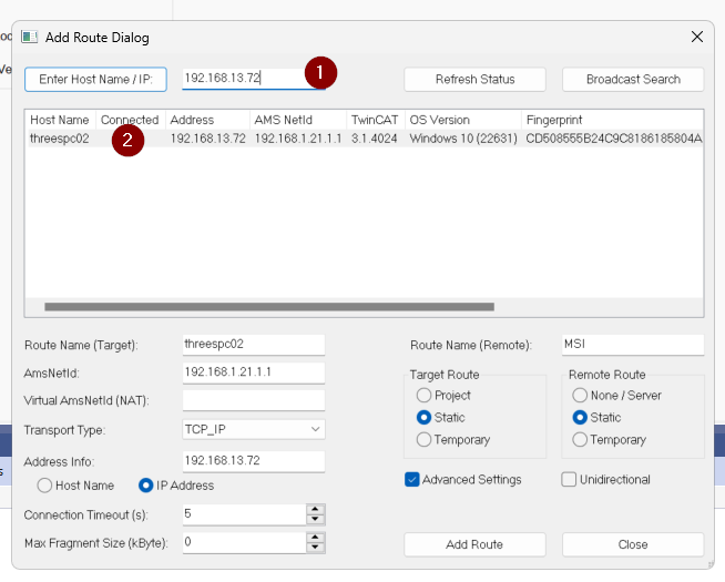
The Route Dialog screen will appear and you should enter the IP of the PC on which TwinCAT Runtime is installed.Then select the PC and the Runtime you wish to connect to.
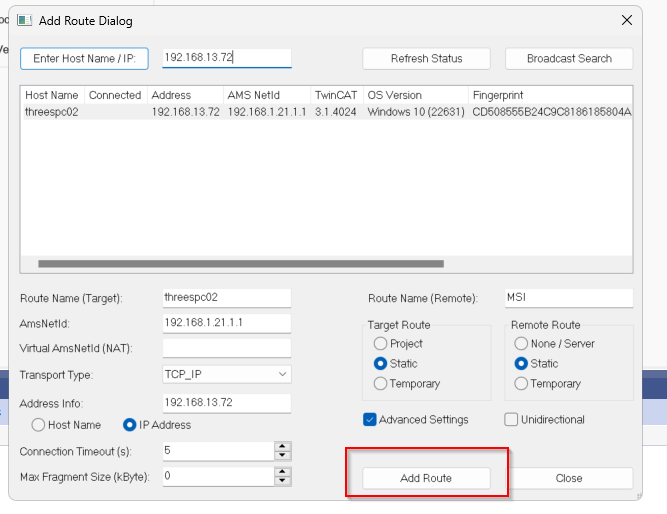
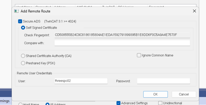
Click Add Route.
Enter the Username and Password of the PC and proceed with OK.
Done!
We can now also check the status of TwinCAT on another PC.
Configure EtherCAT Master
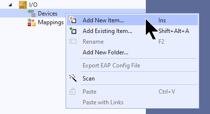
To add an EtherCAT Master, go to I/O>Devices>Add New Item.
Select EtherCAT>EtherCAT Master and proceed with Ok.
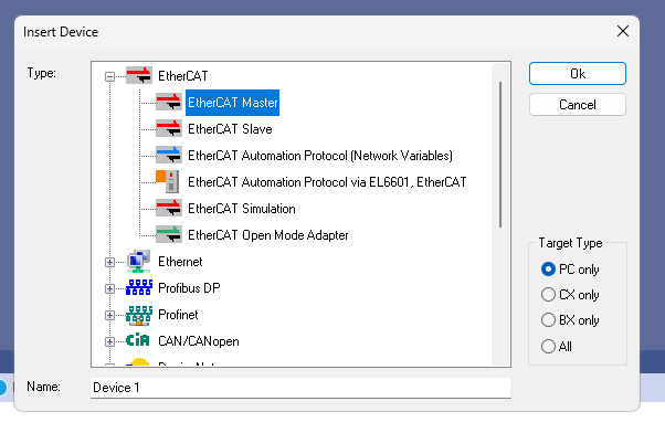
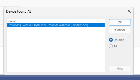
This is the screen to configure the Ethernet Adapter you want to use as an EtherCAT Master, select None once and proceed with Ok.
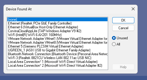
Done!EtherCAT Master has been added.

Configure the PCI Bus/Slot
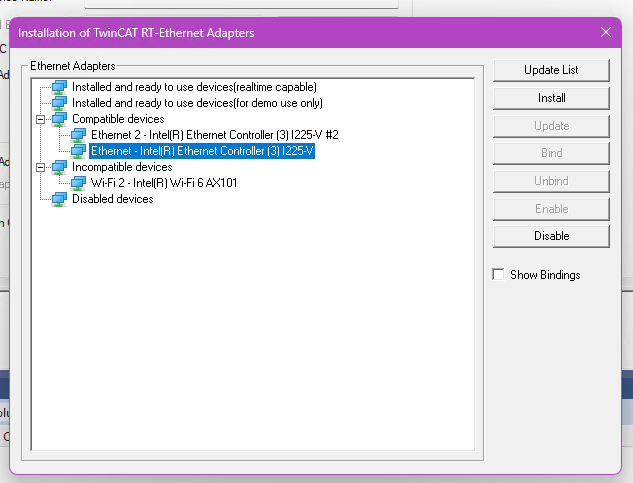
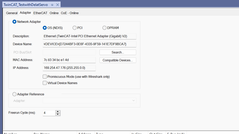
Next, click on Compatible Devices to configure the Ethernet Adapter.
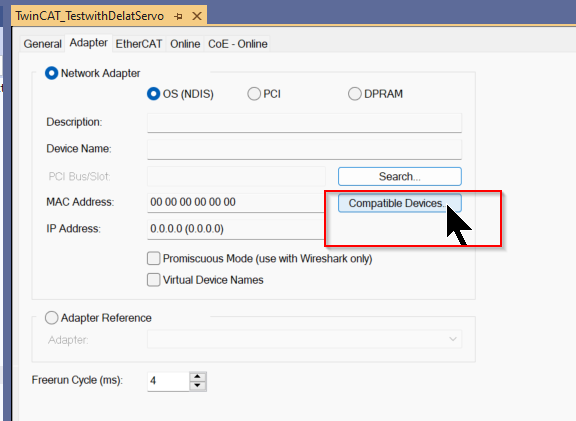
If the screen shown below appears on the corresponding TwinCAT XAE, you need to install the TwinCAT RT-ET Ethernet Adapters.
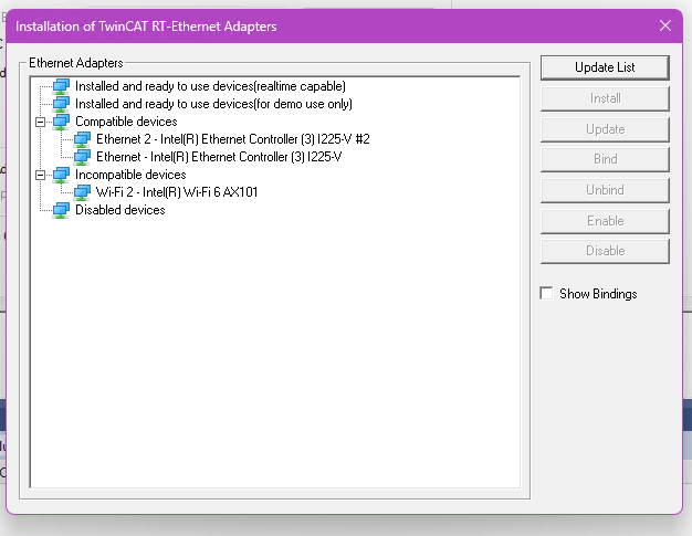
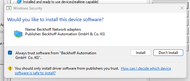
Select the Ethernet Adapter you wish to use as EtherCAT Master and click >Install.
Proceed with Install.
Done!
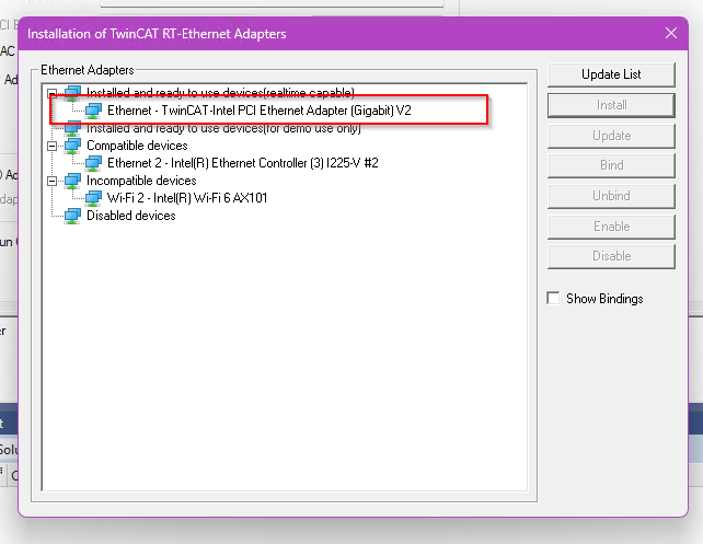
Next, click on the Search button.
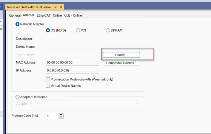
You can now use the Ethernet RT Driver that you have just installed!
Done!
Scan Network
Use TwinCAT’s Auto Scan function to search for EtherCAT Slaves in the network.

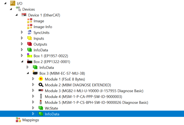
Result
Done!Junction Box from EtherCATP and door locks from Euchern were also searched.
Add PLC
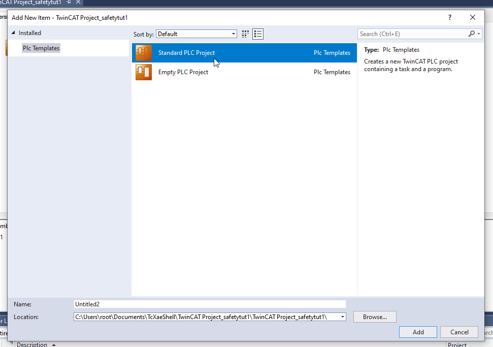
Create a PLC Project with PLCAdd New Item.
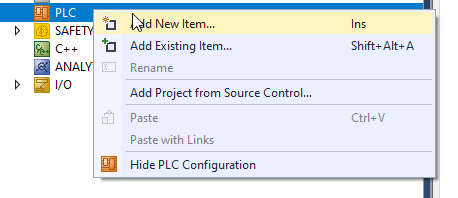
Just select Standard PLC Project > Add and you are good to go.
DUT
DUT_MBM_EC_S7_MLI_3B
This is a structure that defines diagnostic information for the bus module.
| TYPE DUT_MBM_EC_S7_MLI_3B : STRUCT BM_D_RUN //RUN mode ,BM_E_ML1 //Error ML1 ,BM_E_ML2 //Error ML2 ,BM_E_SYS //System Error ,BM_E_G //General Error ,BM_ACK_G //Ack :BOOL; END_STRUCT END_TYPE |
DUT_MGB2_I_MLI_U_Y0000_JJ_IN
This is a structure that defines diagnostic information for the Basic module.
| TYPE DUT_MGB2_I_MLI_U_Y0000_JJ_IN : STRUCT LM_D_RUN //in,Diagnosic runmode ,LM_I_SK //in,Input SK ,LM_E_SM0 //in,Error SubModule1 ,LM_E_SM1 //in,Error SubModule2 ,LM_E_G //in,Error Generally ,LM_I_OD //in,Door Position ,LM_I_OT //in,Tonuge Position :BOOL; END_STRUCT END_TYPE |
DUT_MSM_Button_IN
This is the structure that defines the input for the submodule.
| TYPE DUT_MSM_Button_IN : STRUCT btn:ARRAY[0..7]OF BOOL; END_STRUCT END_TYPE |
DUT_MSM_Button_OUT
This is the structure that defines the output of the submodule.
| TYPE DUT_MSM_Button_OUT : STRUCT Lamp:ARRAY[0..3]OF BOOL; Flash:ARRAY[0..3]OF BOOL; END_STRUCT END_TYPE |
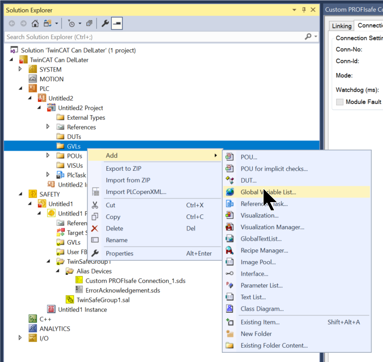
Add GVL
Next, add a Global Variable List.
GVL_Safety
Add GVLs>Add>Global Variable List. This is a GVL for data exchange between TwinCAT Runtime and TwinSAFE.
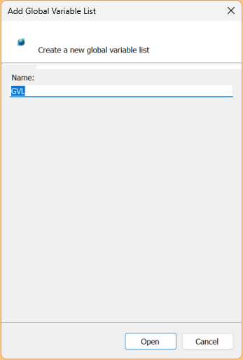
Sets the Global Variable List name.
Define Process IO to exchange data with EL6910 as shown in the figure below.
| {attribute ‘qualified_only’} VAR_GLOBAL RUN AT %Q*:BOOL; ACK AT %Q*:BOOL; B1 AT %I*:BOOL; B2 AT %I*:BOOL; COMACK AT %Q*:BOOL; State AT %I*:UINT; END_VAR |
GVL_Box1
Here is the GVL for Mapping with non-safety data for each Eucher’s Module.
| {attribute ‘qualified_only’} VAR_GLOBAL Door1_MSM_1_P_CA_PPP_SW_ID_9000003_IN AT %I*:USINT; Door1_MSM_1_P_CS_BPH_SW_ID_9000026_IN AT %I*:USINT; Door1_MSM_1_P_CA_PPP_SW_ID_9000003_OUT AT %Q*:USINT; Door1_MSM_1_P_CS_BPH_SW_ID_9000026_OUT AT %Q*:USINT; Door1_MGB2_I_MLI_U_Y0000_JJ_IN AT %I*:ARRAY[0..1]OF USINT; Door1_MGB2_I_MLI_U_Y0000_JJ_OUT AT %Q*:USINT; Door_DUT_MBM_EC_S7_MLI_3B_IN AT %I*:ARRAY[0..1]OF USINT; Door_DUT_MBM_EC_S7_MLI_3B_OUT AT %Q*:USINT; END_VAR |
Program
Here is a simple program to get non-safety data for Eucher door locks and to check the signal and light up the button.
| PROGRAM MAIN VAR SubModule0_Btn0 ,SubModule0_Btn1 ,SubModule0_Btn2:BOOL; SubModule1_Btn0_ETOP ,SubModule1_Btn1 ,SubModule1_Btn2_Key:BOOL; BaseModule:DUT_MGB2_I_MLI_U_Y0000_JJ_IN; FSoEModule:DUT_MBM_EC_S7_MLI_3B; FlashMode:BOOL; END_VAR |
| //Sub Module0 SubModule0_Btn0:=GVL_Box1.Door1_MSM_1_P_CA_PPP_SW_ID_9000003_IN.0; SubModule0_Btn1:=GVL_Box1.Door1_MSM_1_P_CA_PPP_SW_ID_9000003_IN.1; SubModule0_Btn2:=GVL_Box1.Door1_MSM_1_P_CA_PPP_SW_ID_9000003_IN.2; GVL_Box1.Door1_MSM_1_P_CA_PPP_SW_ID_9000003_OUT:=0; GVL_Box1.Door1_MSM_1_P_CA_PPP_SW_ID_9000003_OUT.0:=SubModule0_Btn0; GVL_Box1.Door1_MSM_1_P_CA_PPP_SW_ID_9000003_OUT.1:=SubModule0_Btn1; GVL_Box1.Door1_MSM_1_P_CA_PPP_SW_ID_9000003_OUT.2:=SubModule0_Btn2; IF FlashMode THEN GVL_Box1.Door1_MSM_1_P_CA_PPP_SW_ID_9000003_OUT.3:=SubModule0_Btn0; GVL_Box1.Door1_MSM_1_P_CA_PPP_SW_ID_9000003_OUT.4:=SubModule0_Btn1; GVL_Box1.Door1_MSM_1_P_CA_PPP_SW_ID_9000003_OUT.5:=SubModule0_Btn2; END_IF //SubModule1 SubModule1_Btn0_ETOP:=GVL_Box1.Door1_MSM_1_P_CS_BPH_SW_ID_9000026_IN.0; SubModule1_Btn1:=GVL_Box1.Door1_MSM_1_P_CS_BPH_SW_ID_9000026_IN.1; SubModule1_Btn2_Key:=GVL_Box1.Door1_MSM_1_P_CS_BPH_SW_ID_9000026_IN.2; GVL_Box1.Door1_MSM_1_P_CS_BPH_SW_ID_9000026_OUT:=0; GVL_Box1.Door1_MSM_1_P_CS_BPH_SW_ID_9000026_OUT.0:=SubModule1_Btn0_ETOP; GVL_Box1.Door1_MSM_1_P_CS_BPH_SW_ID_9000026_OUT.1:=SubModule1_Btn1; GVL_Box1.Door1_MSM_1_P_CS_BPH_SW_ID_9000026_OUT.2:=SubModule1_Btn2_Key; IF FlashMode THEN GVL_Box1.Door1_MSM_1_P_CS_BPH_SW_ID_9000026_OUT.3:=SubModule1_Btn0_ETOP; GVL_Box1.Door1_MSM_1_P_CS_BPH_SW_ID_9000026_OUT.4:=SubModule1_Btn1; GVL_Box1.Door1_MSM_1_P_CS_BPH_SW_ID_9000026_OUT.5:=SubModule1_Btn2_Key; END_IF // BaseModule.LM_D_RUN:=GVL_Box1.Door1_MGB2_I_MLI_U_Y0000_JJ_IN[0].0; BaseModule.LM_I_SK:=GVL_Box1.Door1_MGB2_I_MLI_U_Y0000_JJ_IN[0].1; BaseModule.LM_E_SM0:=GVL_Box1.Door1_MGB2_I_MLI_U_Y0000_JJ_IN[0].4; BaseModule.LM_E_SM1:=GVL_Box1.Door1_MGB2_I_MLI_U_Y0000_JJ_IN[0].5; BaseModule.LM_E_G:=GVL_Box1.Door1_MGB2_I_MLI_U_Y0000_JJ_IN[0].7; BaseModule.LM_I_OD:=GVL_Box1.Door1_MGB2_I_MLI_U_Y0000_JJ_IN[1].0; BaseModule.LM_I_OT:=GVL_Box1.Door1_MGB2_I_MLI_U_Y0000_JJ_IN[1].1; // FSoEModule.BM_D_RUN:=GVL_Box1.Door_DUT_MBM_EC_S7_MLI_3B_IN[0].0; FSoEModule.BM_E_ML1:=GVL_Box1.Door_DUT_MBM_EC_S7_MLI_3B_IN[0].1; FSoEModule.BM_E_ML2:=GVL_Box1.Door_DUT_MBM_EC_S7_MLI_3B_IN[0].2; FSoEModule.BM_E_SYS:=GVL_Box1.Door_DUT_MBM_EC_S7_MLI_3B_IN[0].5; FSoEModule.BM_E_G:=GVL_Box1.Door_DUT_MBM_EC_S7_MLI_3B_IN[0].7; GVL_Box1.Door_DUT_MBM_EC_S7_MLI_3B_OUT.7:=FSoEModule.BM_ACK_G; |
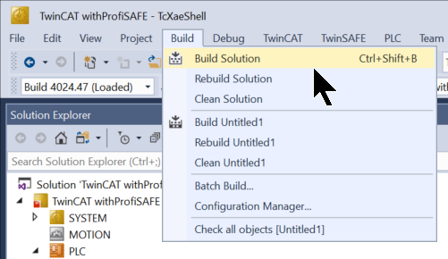
Build
Build the project with Build>Build Solution.
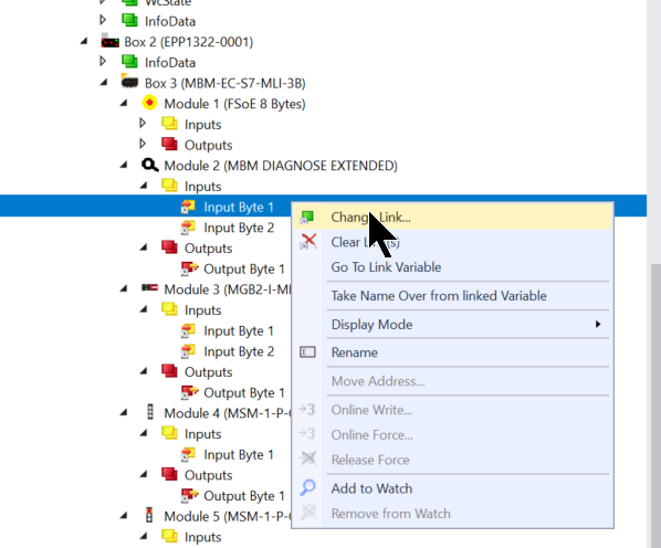
Link
Let’s Mapping the GVL and Eucher door lock non-safety data that we defined earlier.
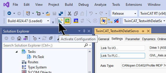
Active Configuration
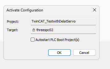
Click Active Configuration and Download the project once to Runtime.
OK to proceed.
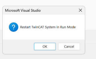
OK softens TwinCAT Runtime to Run Mode.
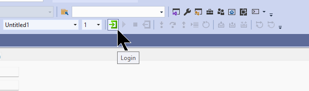
Login
Download the program in Login.
Let’s proceed with Yes.

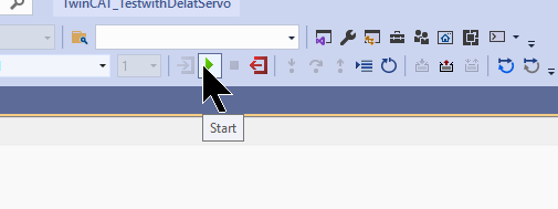
Start
Finally, the Start button executes the Runtime program.
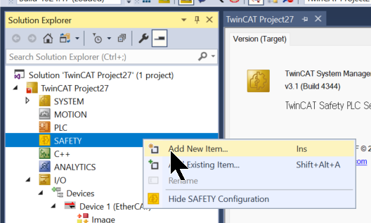
Add Safety
Next, to add the Safety project, go to SAFETY>Add New Item.
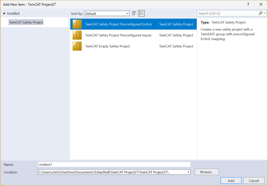
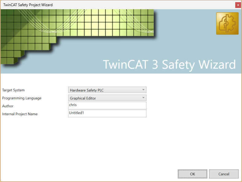
Select the Template called TwinCAT Safety Project Preconfigured ErrAck and add it with Add.
Set Target System to Hardware Safety PLC and press OK to proceed.
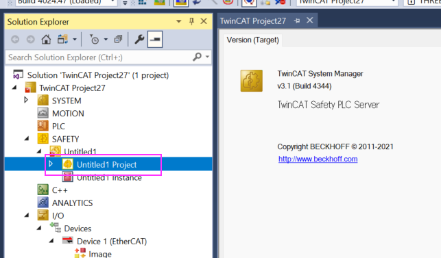
Done!The Safety project has been added.
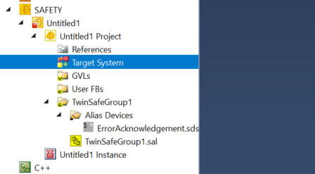
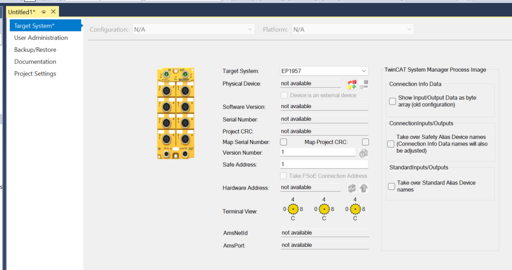
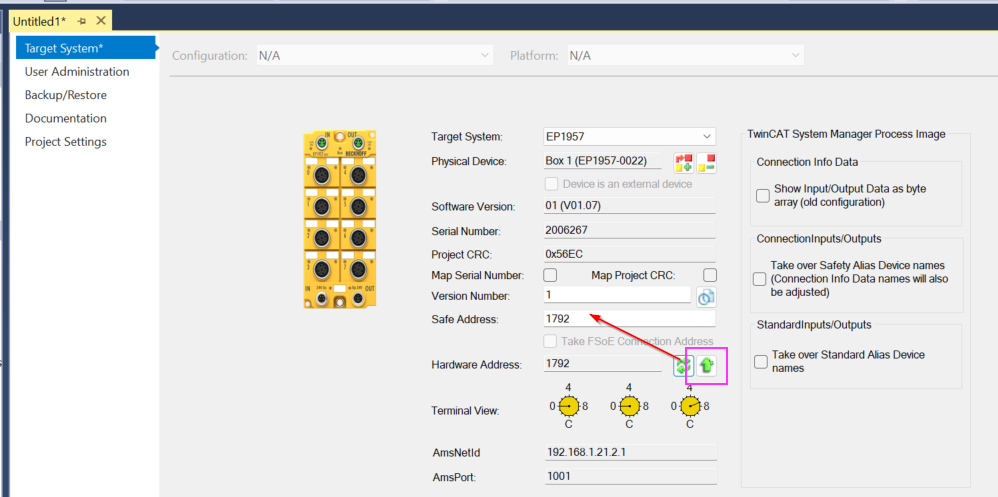
Target System
Set the Target System. Set FSoE Master here.
Set EP1957, which is used in this article, from the Drop-List of the Target System.
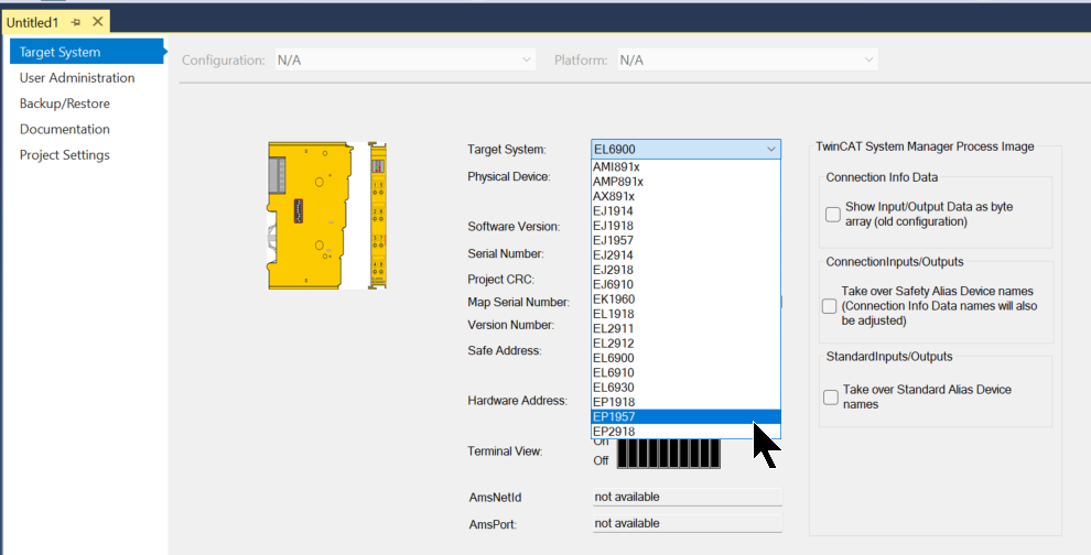
Done!
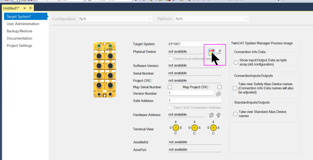
Next, click on the button in the frame and set the actual device connected to the corresponding Target System.
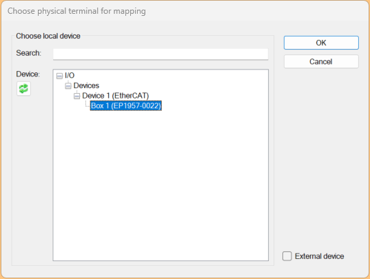
Set EP1957-0022, which you have just searched for in the EtherCAT network.
Done!
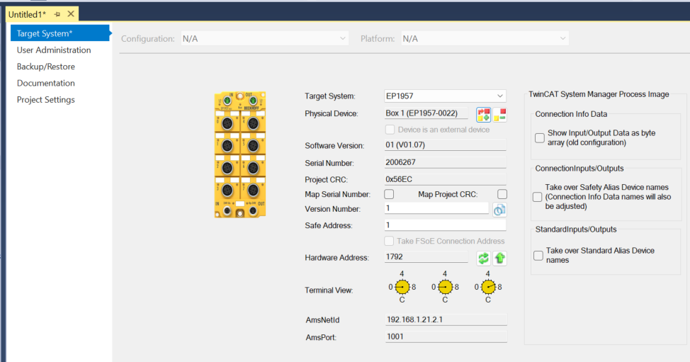
Finally, use the arrow buttons in the frame to Upload the safety address.
Alias Devices
Local IO
To use the IO of EP1957-0022 in the Safety project, add a new device at Alias Devices>Add New Item.
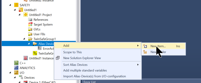
Select Safety>EtherCAT>Beckhoff Automaton Gmbh> EP1957… and add it with the Add button.
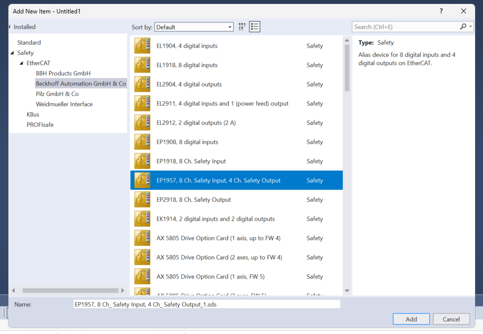
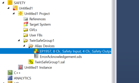
Done!
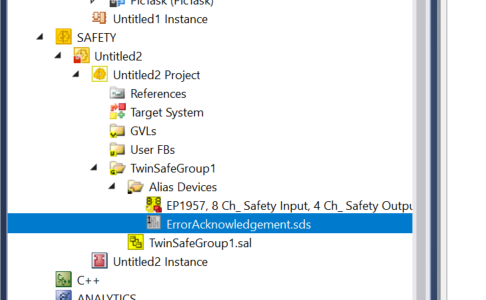
Eucher
Next, add Eucher’s FSOE connection.
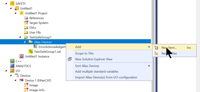
Expand Safety>EtherCAT>EUCHNER to add three types of FSoE connections.
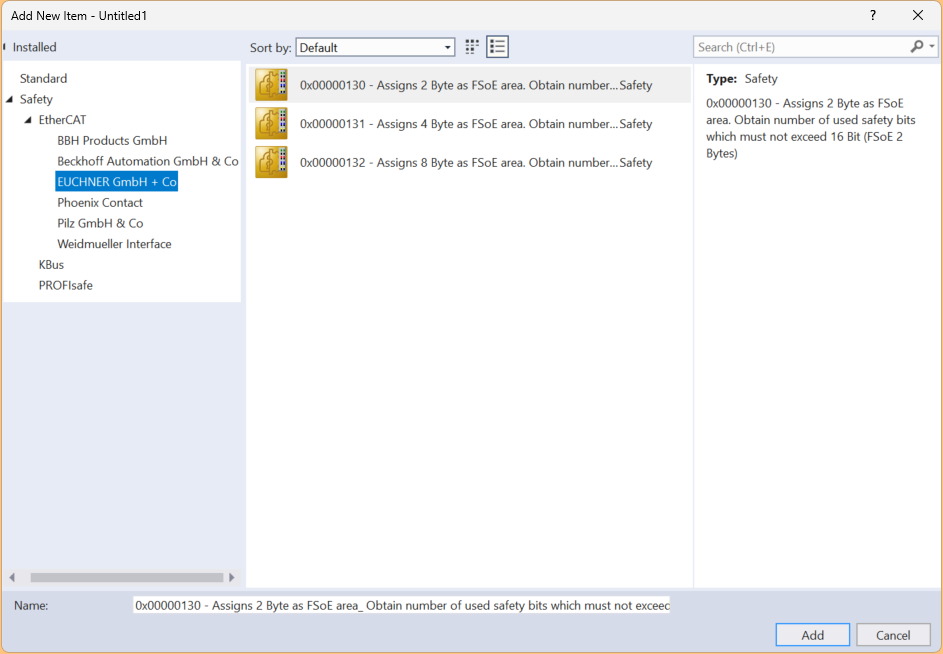
Since the EtherCAT network auto-scan just detected an 8 Bytes FSoE slot, let’s add the same 8 Bytes FSoE input/output data to Alias Devices.
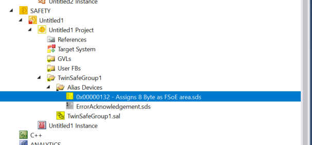
Configure Module
Click on the module you just added to configure the module’s detailed settings.
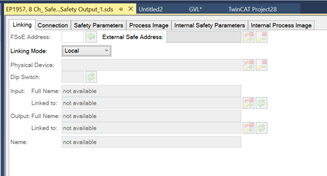
First, set Link Mode to Local. This is because this is the IO of the FSoE master itself.
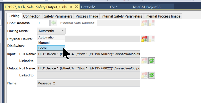
Done!
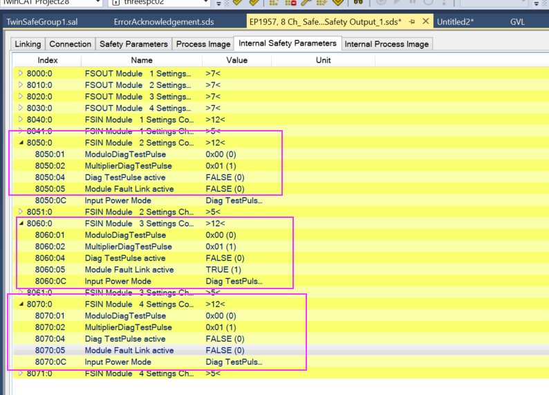
Parameters
Next, click on Internal Safety Parameters and set the safety parameters for EP1957-0022.
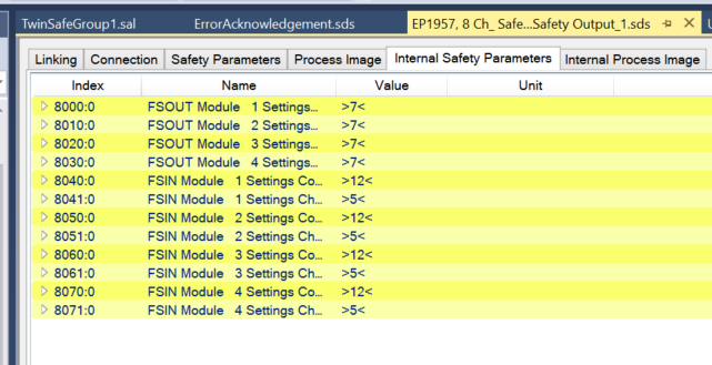
As only output 1 is used in this article, the following parameters for outputs 2, 3 and 4 should be set to False.
- Diag TestPulse active
- Module Fault Link active
Configure Euchner Devices
The next step is to configure the Eucher FSoE device.
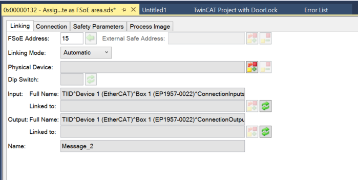
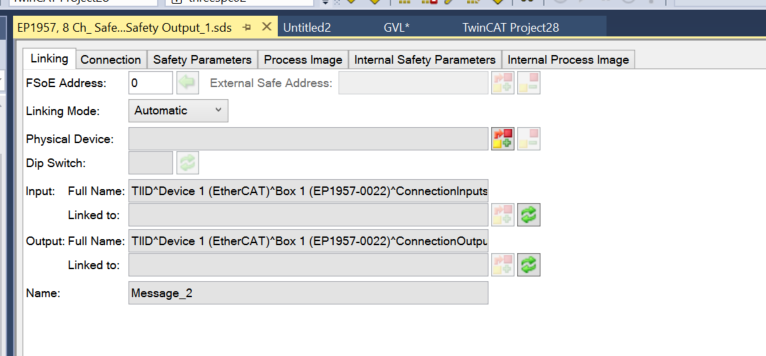
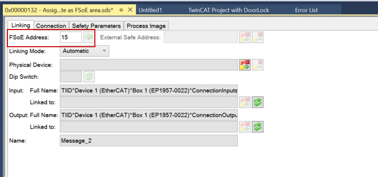
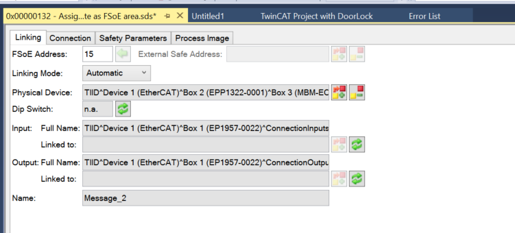
FSoE Address
The FSoE address must be set according to the DIP switch.
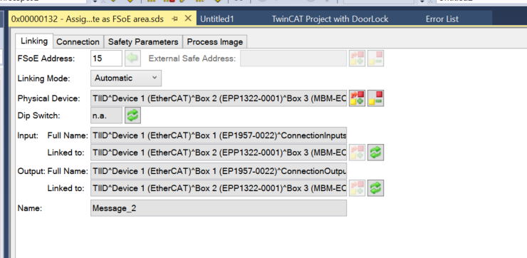
Physical Device
This one sets up the actual hardware chain for Alias Devices’ FSoE Connection.
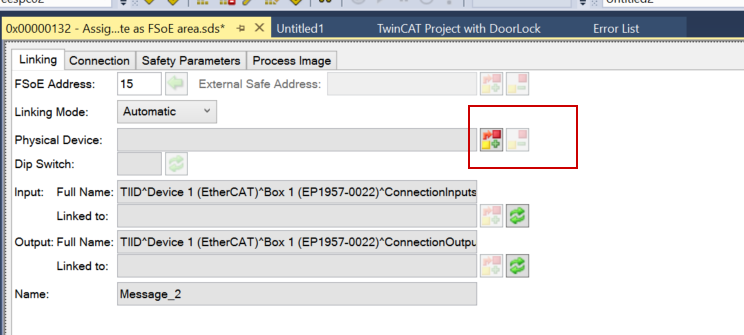
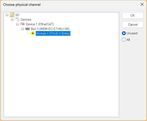
Done!
Once the project is saved, items such as LinkedTo are automatically updated.
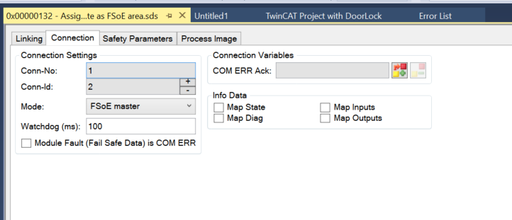
Watchdog
Set the Watch dog in the Connection Tab to match your application.
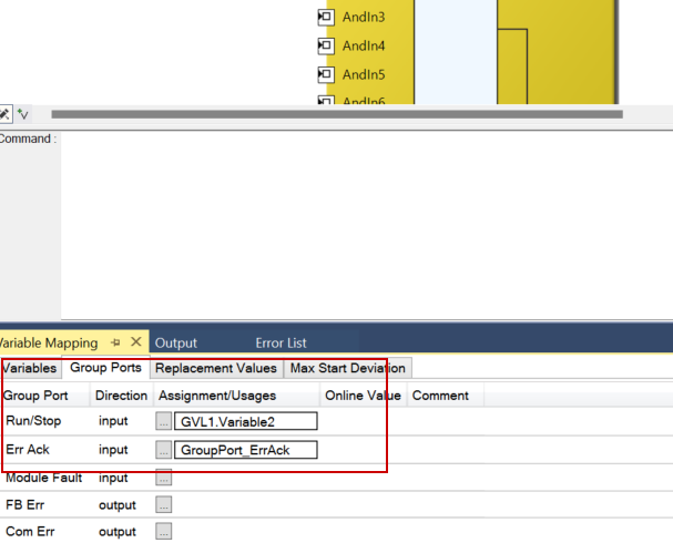
Link Error Ack
Now Mapping the signal to reset the Safety Group.
Click on the button in the frame.
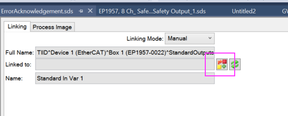
Link with the GVL signal you have just defined in your PLC project.
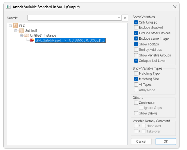
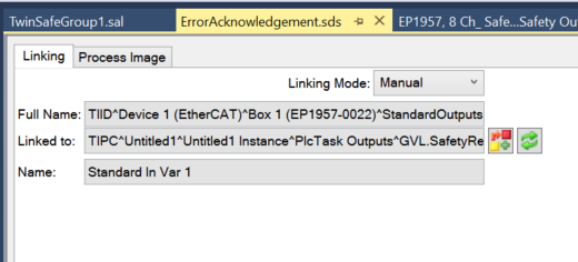
Done!
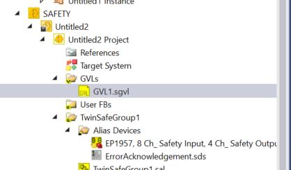
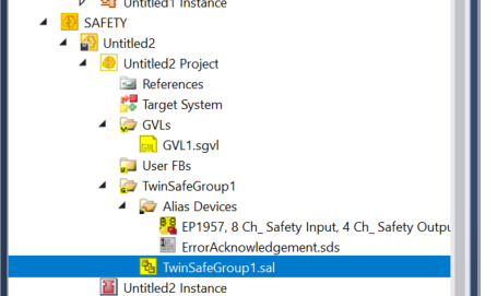
ADD GVL
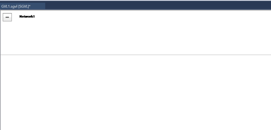
Next, click GVLs>Add>Global Variable List to define safety Global variables in the Safety project.
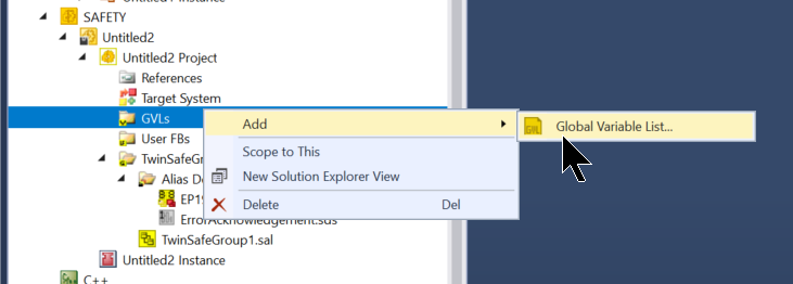
A GVL has been created where safety variables can be defined.
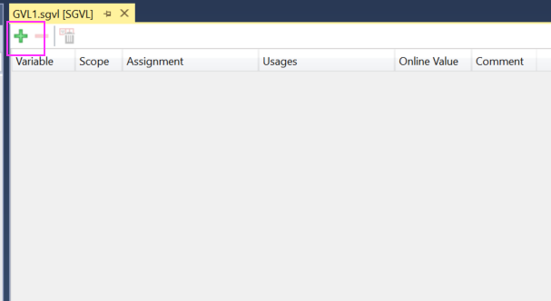
Define IO
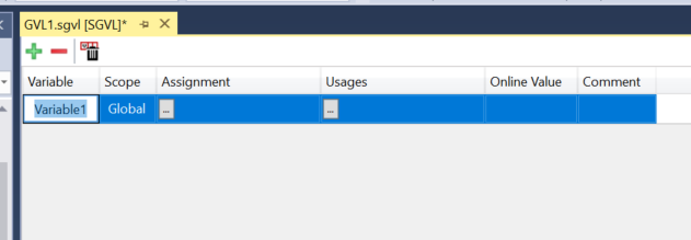
Open the GVL as described earlier and add a new variable using the + button.
New variables have been added.
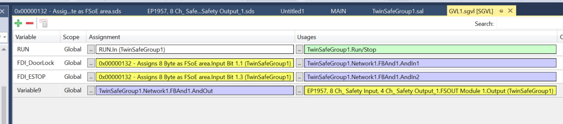
This is the Mapping for this article.
Program
The final step is to create a safety programme.
TwinSAFE’s safety programme is conducted in a basic FBD.
Add SafeAnd Block.
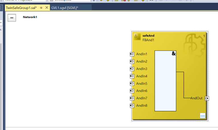
Ensure that the Local output of EP1957-0022 is switched on if the door lock is crossed and if the emergency stop is not pressed.
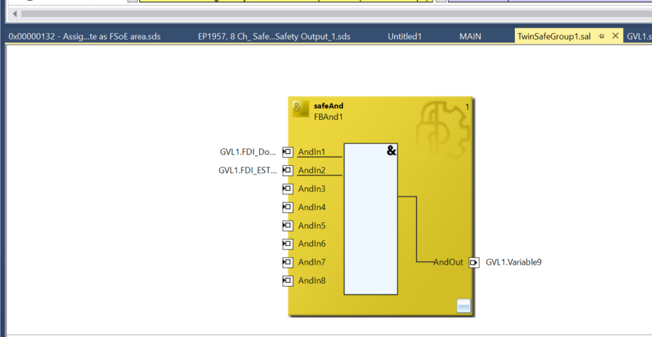
Note that Run/Stop and Err Ack are mapped to the Digital Inputs you have just added.
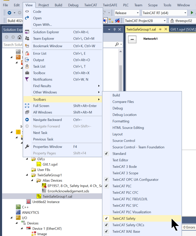
Verify Safety Project
Click View>Toolbars>TwinCAT Safety to display the button for TwinSAFE.
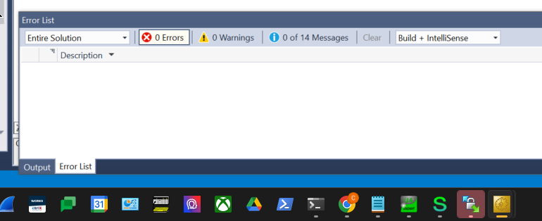
The next step is to compile a safety project with Verify Safety Project.
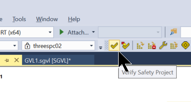
Done!There are no errors in the compilation results.
Download
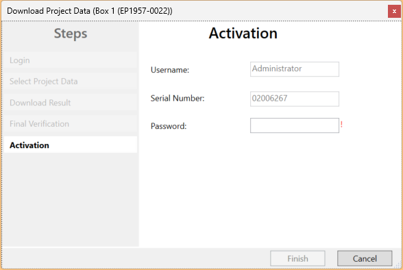
Download the safety programme to EP1957-0022 at Download Safety Project.

Default Username is Administrator and Default Password is TwinSAFE.
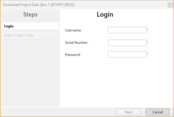
The serial number of EP1957-0022 is next to the actual machine.

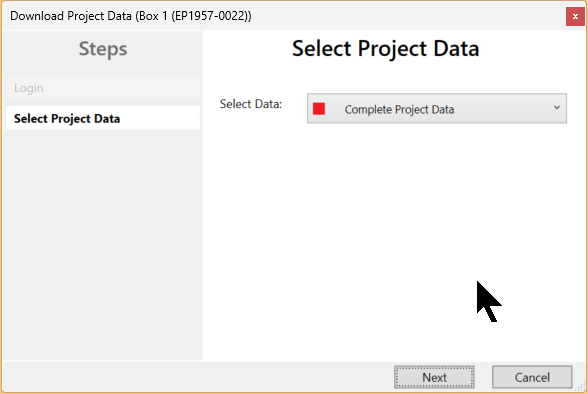
Select Complete Project Data and proceed with Next.
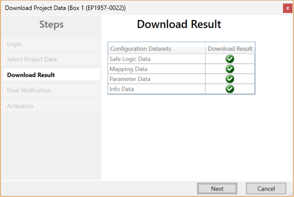
Proceed with Next.
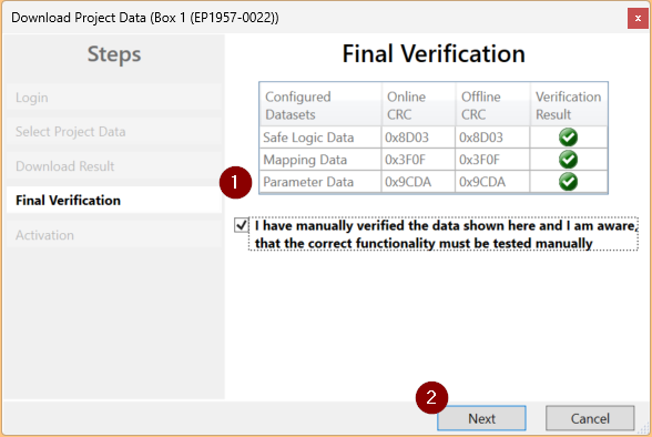
Check Box and proceed with Next.
Enter the password one last time.
Result
Done!FSoE Master EP1957-0022 and EtherCATP Junction Box EPP1322-0001 and Euchner door locks could also communicate without error.
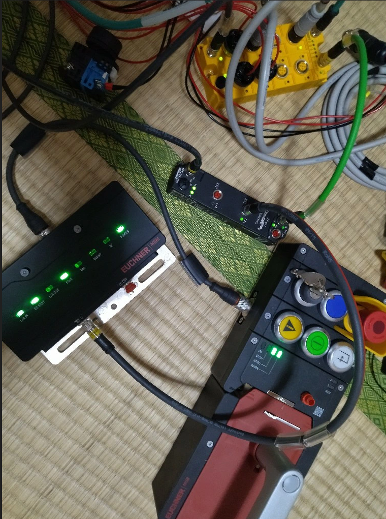
You can check the operation from this video.