In this tutorial I will show you how to use TF5430 to control a planar mover in 100% simulation, without any hardware but just your pc, and configure the visualization in RoboDK.
Because I am also very new in Xplanar, I will just show you some basic movement in this tutorial and I can not explain too much about hardware – I did not see it in the real-world but just in youtube. Sorry about this.
But Do not worry – I will publish more posts about Planar mover in the future.
Hope you like it;)
Install packages
TF5430 is a library for you to control the Xplanar in a more efficient way.All the Function Blocks are included in the Tc3_Mc3PlanarMotion library and combined with the Tc3_physics library.You can image these functions can make your life easily;)!
TF5400
Click the TF5400 exe to start your installation.

Choose english>OK.

The installar is started.

Next>.
Agree the License and Next.
Enter your personal information and Next>.

A Warning is shown if your twincat version is too old.
Please go to the Beckhoff website to download the newest version and install it.

There is no warning if the twincat version that is installed in your machine is matched.
Press Install .
Wait a mins..
TF5400 TC3 Advanced Motion Pack is installed!
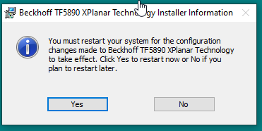
Please restart your machine to apply the modification.
TF5890
Click the TF5890 exe to start your installation.

Choose english>OK.
Next>.

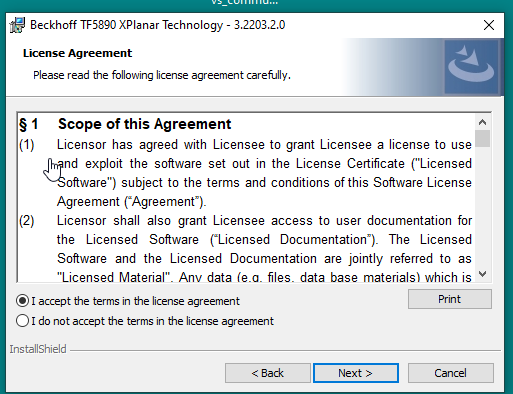
Agree the License and Next.
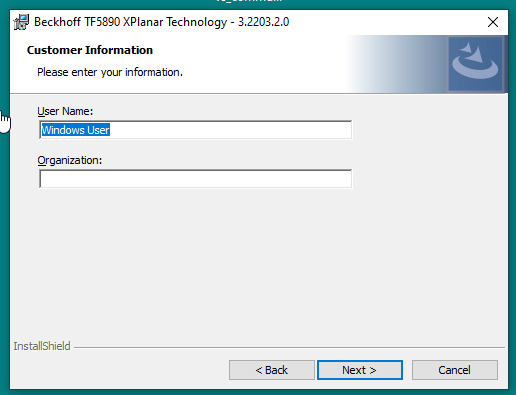
Enter your personal information and Next>.
Install.
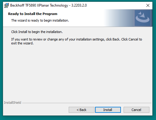
please wait a mins..

Finished!
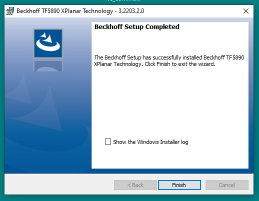
Please restart your machine to apply the modification.
Basic Setup
There are 2 main parts of the basic setup inside your Project.
It is a Motion Project and PLC Project.
Add Motion Project
Go to MOTION>Right Click>Add New Item.

Choose MC Configuration>OK.
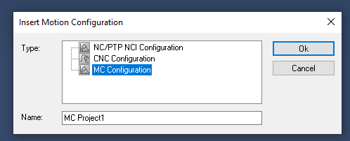
MC Project is created.

Add XPlanar
MC Project>Right Click>Add New Item.

Choose Panar Mover>Ok.
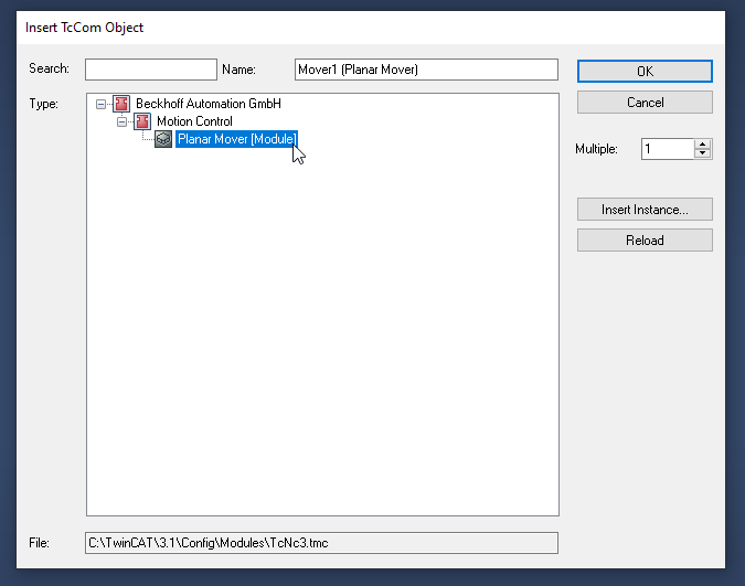
A Planar Mover is added.

Simulation Setup
Click the Mover that you inserted in the previous step.
A set-up screen is shown.
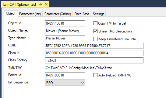
Open the Parameter(Init)Tab and check the Show Hidden Parameters’s Checkbox.
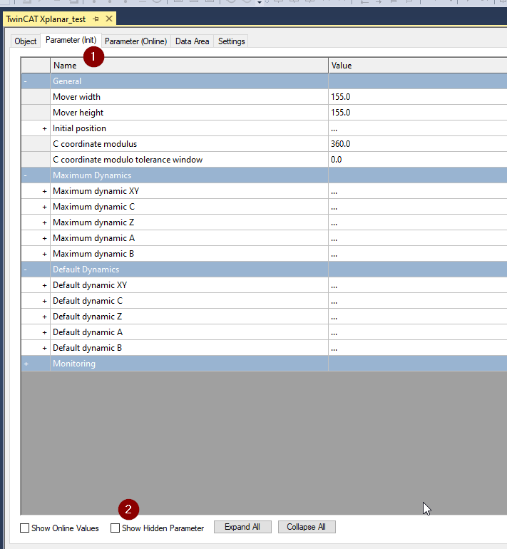
Some orange parameters are shown here now.
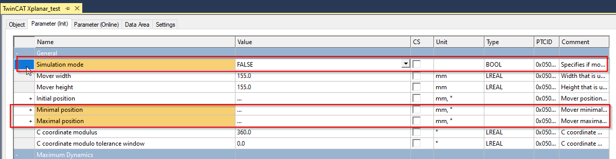
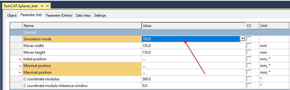
Change the Simulation Mode’s Value to TRUE.
ADD PLC
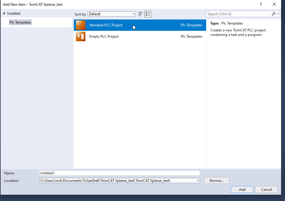
Now we can insert a PLC in our project. Go to PLC>Add New Item.

Insert a Standard PLC Project.
Add Reference
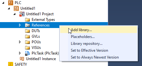
Now we can add the library to our PLC project. Go toReference>Right Click >Add library.
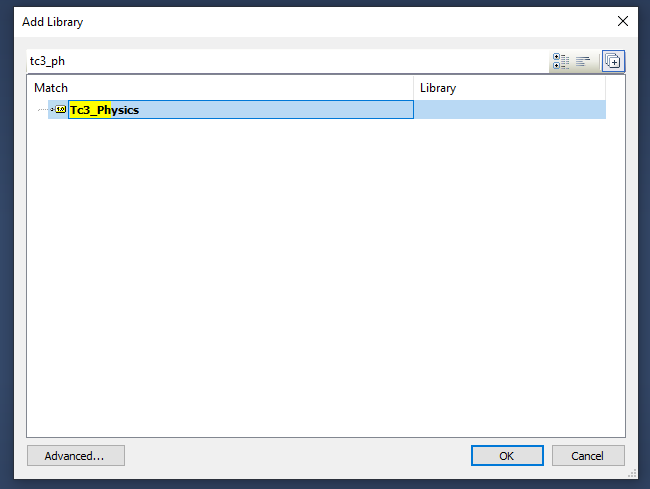
Insert Tc3_physics library in your project.
Insert Tc3_Mc3PlanarMotion in your project.

Add MC_PlanarMover
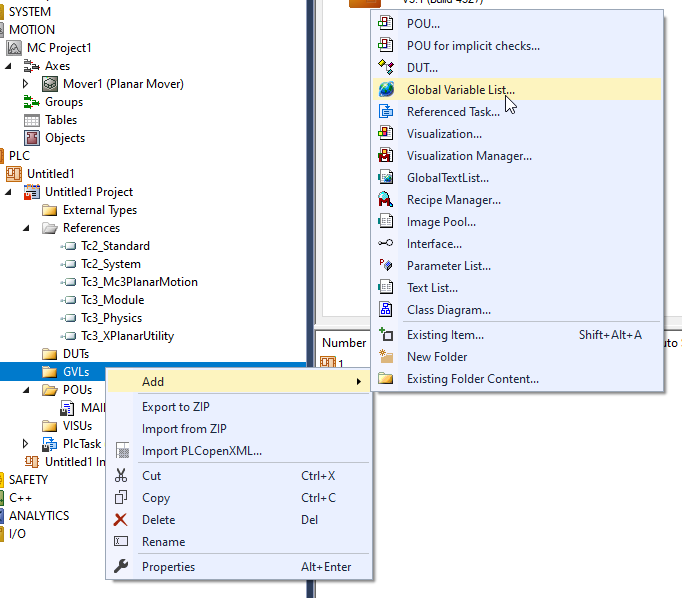
We will define the Planar Object in our Project. Go to GVLs>Add and create a Global Variable List.
define a MC_PlanarMover object in the Global variable list.

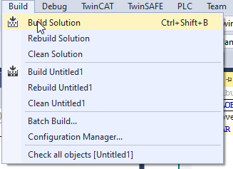
Go to Build>Build Solution to rebuild your project.
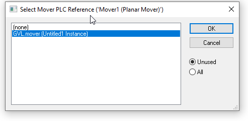
Link to Mover
Click the Mover1.
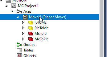
Open the Settings Tab and Click the “Link to PLC” button.

Select the Mover object and press the OK button.
API
Tc3_Physics and Tc3_Mc3PlanarMotion are the libraries that are used for XPlanar Control.
In this tutorial I will explain the Function Block and DUT that are used here.
DUT
EPlanarObjectType
A DUT that defines the Object type of the Planar.
| Name | Type | Value | Description |
| Invalid | UNIT | 0 | Components are not ready or not connected |
| None | UNIT | 301 | No Planar |
| Mover | UNIT | 302 | Planar Mover |
| Track | UNIT | 303 | Planar Track |
| Environment | UNIT | 304 | Planar Environment |
PlanarObjectInfo
A DUT that defines the ObjectType and ID of the Planar.
| Name | Type | Description |
| ObjectType | EPlanarObjectType | The type of Object |
| Id | UDINT | The Object ID |
MC_PLANAR_STATE
An enum that presents the status of the component.
| Name | Type | Value | Description |
| Invalid | UNIT | 0 | Component is not ready or not connected. |
| Disabled | UNIT | 1 | Component is disabled |
| Enabling | UNIT | 2 | Component is enabling |
| Enabled | UNIT | 3 | Component is enabled |
| Disabling | UNIT | 4 | Component is disabled |
| Error | UNIT | 5 | Component is in error status |
| ErrorPending | UNIT | 6 | Component is changing the status from normal to error |
| Resetting | UNIT | 7 | Component is resetting the error |
MoverVector
A DUT that presents a Vector with 6 coordinate values.We can use this MoverVector as position or speed ,etc.
| Name | Type | Description |
| x | LREAL | x coordinate |
| y | LREAL | y coordinate |
| z | LREAL | z coordinate |
| a | LREAL | a coordinate |
| b | LREAL | b coordinate |
| c | LREAL | c coordinate |
MoverBusy
A DUT that presents the PlanarMover‘s coordinate movement status.
| Name | Type | Description |
| busyMover | BIT | True=PlanarMover is Busy |
| busyXYC | BIT | True=XYC coordinate is Busy |
| busyX | BIT | True=x coordinate is Busy |
| busyY | BIT | True=y coordinate is Busy |
| busyZ | BIT | True=z coordinate is Busy |
| busyA | BIT | True=a coordinate is Busy |
| busyB | BIT | True=b coordinate is Busy |
| busyC | BIT | True=c coordinate is Busy |
ST_MoveToPositionOptions
The options of Planar Mover’s MoveToPosition command.
| Name | Type | Default | Description |
| useOrientation | BOOL | TRUE | If true, the target orientation is also reachedat the end of the movement. |
ST_ExternalSetpointGenerationOptions
The options of Planar Mover’s ExternalSetpointGeneration command.
| Name | Type | Default | Description |
| mode | MC_EXTERNAL_SET_POSITION_MODE | MC_EXTERNAL_SET_POSITION_MODE.Absolute | Mode can be relative or absolute, relative can be used parallel to all other commands, absolute onlyalone |
MC_EXTERNAL_SET_POSITION_MODE
An enum that presents the External setpoint generation mode.
| Name | Type | Initial | Description |
| Invalid | UINT | 0 | Invalid data |
| Absolute | UINT | 1 | absolute positioning |
| Relative | UINT | 2 | Relative positioning |
| None | UINT | 3 | no External setpoint |
PositionXYC
A Function Block to configure the XYZ position.This Function Block can not be directly called in the user program and please use the method of its instance.
SetValuesXY
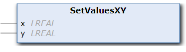
VAR_INPUT
| Name | Type | Description |
| x | LREAL | x position |
| y | LREAL | y position |
Example
| VAR position : PositionXYC; x : LREAL := 20.0; y : LREAL := 5.3; VAR_END position.SetValuesXY(x, y); |
MC_PlanarMover
The MC_PlanarMover Object is used to control the Planar.This Function Block can not be directly called in the user program and please use the method of its instance.
MoveToPosition
Initiates a direct movement to the specified position.
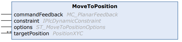
VAR_INPUT
| Name | Type | Description |
| commandFeedback | MC_PlanarFeedback | The Feedback of the command |
| constraint | IPlcDynamicConstraint | The constraint of Planar |
| options | ST_MoveToPositionOptions | The moving Option |
VAR_INOUT
| Name | Type | Description |
| targetPosition | PositionXYC | Target value |
Enable
Enable the Planar Mover.

VAR_INPUT
| Name | Type | Description |
| commandFeedback | MC_PlanarFeedback | The Feedback of the command |
Update
This method must be triggered each cycle,to update the internal state of the object.

Disable
Disable the Planar mover.
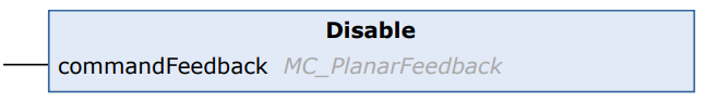
VAR_INPUT
| Name | Type | Description |
| commandFeedback | MC_PlanarFeedback | The Feedback of the command |
Reset
Reset the error of Planar mover.

VAR_INPUT
| Name | Type | Description |
| commandFeedback | MC_PlanarFeedback | The Feedback of the command |
MoveZ
Initiates a movement for the z component.
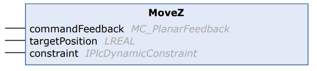
VAR_INPUT
| Name | Type | Description |
| commandFeedback | MC_PlanarFeedback | The Feedback of the command |
| targetPosition | LREAL | The Target Position of Planar mover |
| constraint | IPlcDynamicConstraint | Dynamic constraints for this movement. |
MoveA
Initiates a movement for the A component.

VAR_INPUT
| Name | Type | Description |
| commandFeedback | MC_PlanarFeedback | The Feedback of the command |
| targetPosition | LREAL | The Target Position of Planar mover |
| constraint | IPlcDynamicConstraint | Dynamic constraints for this movement. |
MoveB
Initiates a movement for the B component.

VAR_INPUT
| Name | Type | Description |
| commandFeedback | MC_PlanarFeedback | The Feedback of the command |
| targetPosition | LREAL | The Target Position of Planar mover |
| constraint | IPlcDynamicConstraint | Dynamic constraints for this movement. |
MoveC
Initiates a movement for the C component.
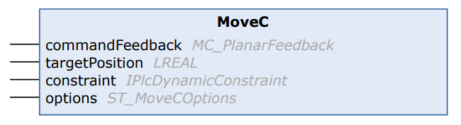
VAR_INPUT
| Name | Type | Description |
| commandFeedback | MC_PlanarFeedback | The Feedback of the command |
| targetPosition | LREAL | The Target Position of Planar mover |
| constraint | IPlcDynamicConstraint | Dynamic constraints for this movement. |
StartExternalSetpointGeneration
Starts the external setpoint generation, the user must supply setpoints from this PLC cycle on in every PLC cycle.
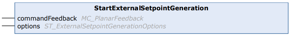
VAR_INPUT
| Name | Type | Description |
| commandFeedback | MC_PlanarFeedback | The Feedback of the command |
| options | ST_ExternalSetpointGenerationOptions | The option of the movement |
StopExternalSetpointGeneration
Ends the external setpoint generation, called after last SetExternalSetpoint (in the same PLC cycle).

VAR_INPUT
| Name | Type | Description |
| commandFeedback | MC_PlanarFeedback | The Feedback of the command |
SetExternalSetpoint
Sets the external setpoint for the Planar Mover, must be called each PLC cycle during external setpoint generation.
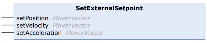
VAR_INPUT
| Name | Type | Description |
| setPosition | MoverVector | The position setpoint is sent to the Planar Mover. |
| setVelocity | MoverVector | The velocity setpoint is sent to the Planar Mover. |
| setAcceleration | MoverVector | The acceleration setpoint is sent to the Planar Mover. |
MC_PlanarFeedback
Displays specific command status information for an associated command, given back by the MC Project.
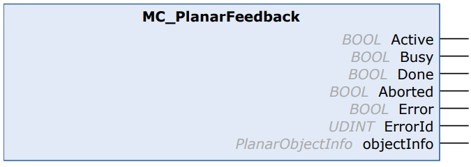
VAR_OUTPUT
| Name | Type | Description |
| Active | BOOL | Command is received and pedding to execute |
| Busy | BOOL | Command is Executing |
| Done | BOOL | Command is Done without Error |
| Aborted | BOOL | Command is Aborted |
| Error | BOOL | Error occurs while the command is executing |
| ErrorId | BOOL | The Error ID |
| ObjectInfo | PlannarObjectInfo | The object infomration |
Update
Updates the internal state of the object.
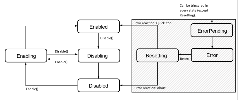
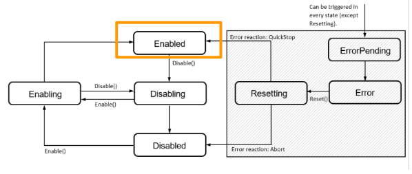
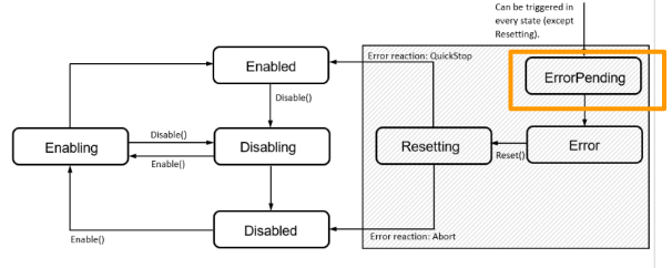
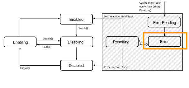
Flow
Here is a Flow from the manual to show the status of the moving diagram.There is a total of 7 status of a component.
- Enabling
- Enabled
- Disabling
- Disabled
- Resetting
- ErrorPending
- Error.
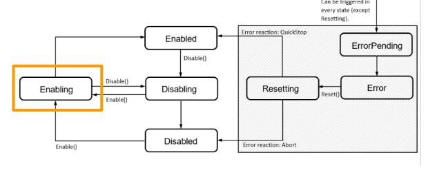
Enabling
Component will shift the status to Enabling if a Enable command is received. We can use the Disable command to shift the status to Disabling.
Enabled
Component will shift the status to Enabled Finally from Enabling.User can use Fully features of that component,and also we can use the Disable command to shift the status to Disabling.
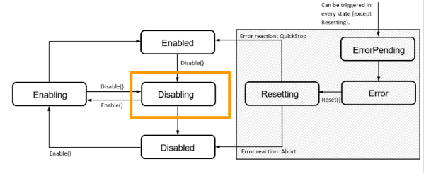
Disabling
The component will shift to Disabling status while a Disable command is received, We can use the Enable command to change the status of the component to Enabling.
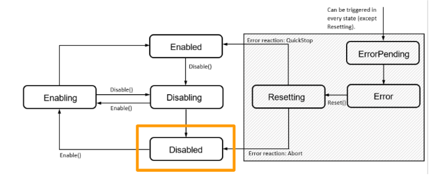
Disabled
The status of the component will change to Disabled while the system is started up.We can use the Enable command to shift the component status to Enabling.
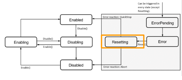
Resetting
A status to indicate the component is in an error condition and processing is a reset process.The status will shift to Enabled finally if no error occurs , or shift to Disabled if an error is still present.
ErrorPending
Error occurs and shifts the status from last to Error.
Error
Component is in the Error state and we can send a Reset command to reset it.
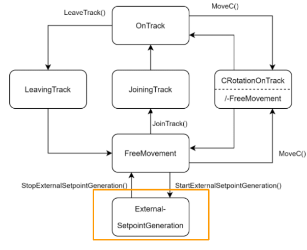
Planar mover command diagram
There are 6 command modes in Planar mover.
- OnTrack
- LeavingTrack
- JoiningTrack
- ExternalSetpointGeneration
- CRotationFreeMovement/-
- FreeMovement
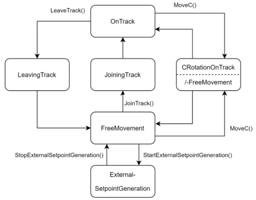
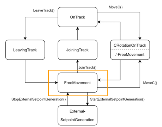
FreeMovement
This is my first tutorial of the Xplanar series and let’s take the easy task first. It is in FreeMovement mode.
Mover will automatically change to this mode while the status is shifted to Enabled.
In this Mode, we can use the MoveToPosition command to operate a Free movement.
And Also we can shift the mode to ExternalSetpointGeneration or JoiningTrack..etc.
It is very flexible.
ExternalSetpointGeneration
ExternalSetpointGeneration is the mode that allows us to perform a relative movement.
Implementation-1 Move it!
Let’s move the Planar mover by the MoveToPosition command in FreeMovement Mode.
GVL
In the Global Variable List we will define the MC_PlanarMoverobject and MC_PlanarFeedback object to receive the status of the command.
| VAR_GLOBAL mover:MC_PlanarMover; commandFeedback:MC_PlanarFeedback; END_VAR |
MAIN
The workflow is Init the Planar mover>Enable the Planar >Use the MoveToPosition Command>back to init.
VAR
| PROGRAM MAIN VAR iStep :UDINT; moverStatus :MC_PLANAR_STATE; counter :INT; TargetPositions :ARRAY[0..5]OF PositionXYC; i :INT; bGo :BOOL; bReset :BOOL; bDisable :BOOL; END_VAR VAR CONSTANT cStepXplanarInit :UDINT :=0; cStepXplanarEnable :UDINT :=10; cStepMoveToPosition :UDINT :=20; cStepDisable :UDINT :=99; cStepReset :UDINT :=98; END_VAR |
Code
| //Sending Data to RoboDK by OPCUA GVL2RoboDK.xplanar1.pos.ActPos:=GVL.mover.MCTOPLC.ACT.ActPos; //Target Positions Init TargetPositions[0].SetValuesXY(0,200); TargetPositions[1].SetValuesXY(200,-200); TargetPositions[2].SetValuesXY(100,20); TargetPositions[3].SetValuesXY(40,0); TargetPositions[4].SetValuesXY(110,60); TargetPositions[5].SetValuesXY(50,200); //xPlanar Status moverStatus:=GVL.mover.MCTOPLC.STD.State; //Disable IF bDisable THEN GVL.mover.Disable(commandFeedback:=GVL.commandFeedback); iStep:=cStepDisable; END_IF //Reset IF bReset THEN GVL.mover.Reset(commandFeedback:=GVL.commandFeedback); iStep:=cStepReset; END_IF CASE iStep OF cStepXplanarInit: GVL. mover.Enable(commandFeedback:=GVL.commandFeedback); iStep := cStepXplanarEnable; cStepXplanarEnable: IF GVL.mover.MCTOPLC.STD.State = MC_PLANAR_STATE.Enabled THEN iStep := cStepMoveToPosition; END_IF counter:=0; bGo:=TRUE; cStepMoveToPosition: IF bGo THEN GVL.mover.MoveToPosition( commandFeedback:=GVL.commandFeedback ,targetPosition:=TargetPositions[counter] ,constraint:=0 ,options:=0 ); bGo:=FALSE; END_IF; IF GVL.commandFeedback.Done THEN counter:=counter+1; bGo:=TRUE; IF counter > 5 THEN iStep:=cStepXplanarEnable; END_IF END_IF cStepDisable: IF moverStatus= MC_PLANAR_STATE.Disabled THEN bDisable:=FALSE; iStep:=cStepXplanarInit; END_IF cStepReset: IF moverStatus= MC_PLANAR_STATE.Enabled THEN bReset:=FALSE; iStep:=cStepXplanarInit; END_IF END_CASE //Update GVL.mover.Update(); GVL.commandFeedback.Update(); |
Result
We can see the actual xyzabc coordinate of the planar mover is changing – it means that the planar mover is moving now.
* MCTOPLC.ACT is the actual value of your mover.

Simulation With RoboDK
I would like to use the TF5890 Xplanar Configurator to implement the visualization.but I can not solve the error of TCCOM not found or No Services.. RoboDK is my next choice.
And also we can add the robot inside RoboDK later, it may be more convenient.
TO DO:Search the CAD File of the xplanar Mower and parts..
Reference Link
Here is my other tutorial to show you how to integrate RoboDK in TwinCAT3.
Add a “Plate” Object
Let’s add a plate object first. I would like to mention that the size of the plate may not be the same as the Planar mover, but it would be ok for just simulation and learning.
Start your RoboDK software and click the earth icon.
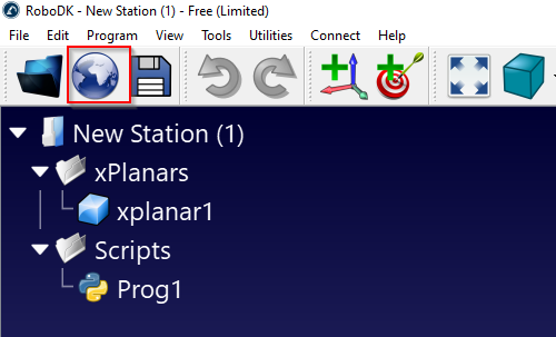
THe RoboDK Library website will be automatically opened in your default browser.
Go to Type and select Object>Select the RoboDK RDK Plate.
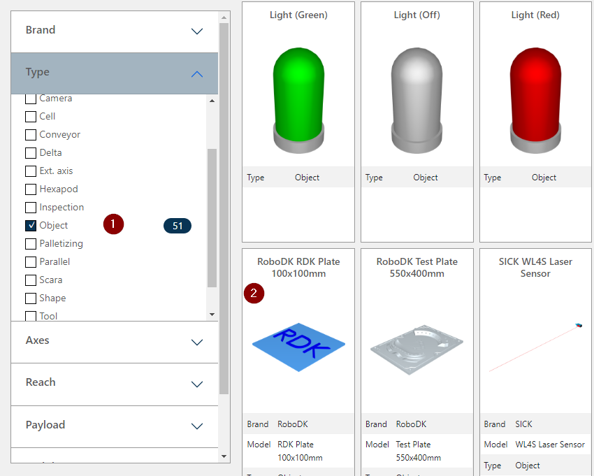
Download the plate object.
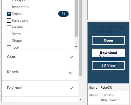
Click the Button with File icon.

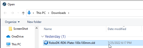
Open the .sld that you downloaded before.
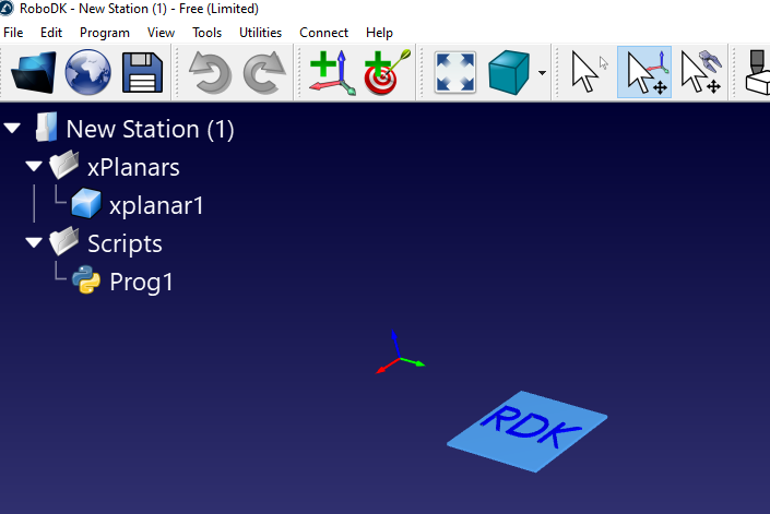
Rename the plate
we can rename the name of your plate.

Right click>Rename and change the name to xplanar1. This xplanar1 is used in the Python script.

Add Python Script
Click the Add Python Program button in the Toolbars.
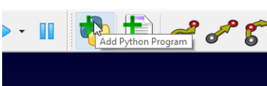
A Script named Prog1 is created.

Program
Right Click the Script>Edit Python Script.

In this python script I will configure an OPCUA Client in ROBODK and receive the Coordinate data of Xplanar from TwinCAT and use these data to update the plate position.
So easy and no hard staff.
| from robodk import robolink # RoboDK API from robodk import robomath # Robot toolbox from opcua import Client,ua RDK = robolink.Robolink() from robodk import * # RoboDK API from robolink import * # Robot toolbox XPLANAR=’xplanar1′ ENDPOINT=”opc.tcp://DESKTOP-7FE1JP2:4840″ client=Client(ENDPOINT) NODES=’ns=4;s=GVL2RoboDK.xplanar1.pos.ActPos’ s # Program example: xplanar = RDK.Item(XPLANAR) if xplanar.Valid(): print(‘Item selected: ‘ + xplanar.Name()) print(‘Item posistion: ‘ + repr(xplanar.Pose())) client.connect() print(‘Connected to OPCUA server..’) NodeFromServer=client.get_node(NODES) client.load_type_definitions() # while True: Actpos=NodeFromServer.get_value() # CurrentPos=xyzrpw_2_pose([Actpos.x,Actpos.y,Actpos.z,Actpos.a,Actpos.b,Actpos.c]) xplanar.setPoseAbs(CurrentPos) client.disconnect() |
TwinCAT Side
After we prepared the RoboDK Side, there were some modifications in the TwinCAT side also. Some DUT,variables and programs are added.
Reference Link
Here is the tutorial to show you how to startup an OPC UA Server in Beckhoff TwinCAT TF6100.
DUT_Pos
Define a MoverVector variable with the OPC UA Attribute and StructedType attribute.
| TYPE DUT_Pos : STRUCT {attribute ‘OPC.UA.DA’ := ‘1’} {attribute ‘OPC.UA.DA.StructuredType’ := ‘1’} ActPos :MoverVector; END_STRUCT END_TYPE |
DUT_xPlanar
Define a DUT_xPlanar to group all Planar data.
| TYPE DUT_xPlanar : STRUCT pos :DUT_Pos; END_STRUCT END_TYPE |
GVL2RoboDK
Create a GVL that is named GVL2RoboDK and define the variables for OPC UA Data exchange.
| {attribute ‘qualified_only’} VAR_GLOBAL {attribute ‘OPC.UA.DA’ := ‘1’} {attribute ‘OPC.UA.DA.StructuredType’ := ‘1’} xplanar1 :DUT_xPlanar; END_VAR |
MAIN
Same as Example1, but just add 1 line.
| //Sending Data to RoboDK by OPCUA GVL2RoboDK.xplanar1.pos.ActPos:=GVL.mover.MCTOPLC.ACT.ActPos; |
Result
Now we can see how the planar is moving in RoboDK!
Implementation-2 Move axis by axis!
The Next example is to perform a movement axis by axis.First is AB then CZ.
GVL
Same as GVL in Example1 but just creates an array of MC_PlanarFeedback.Because we will send the MoveA,MoveB,MoveZ,MoveC commands to planar and need to check if the command is done or not separately.
| {attribute ‘qualified_only’} VAR_GLOBAL mover:MC_PlanarMover; commandFeedback:MC_PlanarFeedback; commandFeedbacks:ARRAY[0..4]OF MC_PlanarFeedback; END_VAR |
MAIN
The Flow is Init the planar mover>Enable the Planar Mover>Send the MoveA,MoveB Command>Send the MoveC MoveZ Command>End.
VAR
| PROGRAM MAIN_Example2 VAR iStep :UDINT; moverStatus :MC_PLANAR_STATE; counter :INT; i :INT; bGo :BOOL; bReset :BOOL; bDisable :BOOL; TargetA :LREAL:=1.0; TargetB :LREAL:=-1.0; TargetC :LREAL:=10.0; TargetZ :LREAL:=5.0; ZeroPosition :PositionXYC; binit :BOOL; END_VAR VAR CONSTANT cStepXplanarInit :UDINT :=0; cStepResetPosition :UDINT :=5; cStepXplanarEnable :UDINT :=10; cStepMoveAB :UDINT :=20; cStepDelay :UDINT :=30; cStepMoveCZ :UDINT :=40; cStepDisable :UDINT :=99; cStepReset :UDINT :=98; END_VAR |
Code
| //Sending Data to RoboDK by OPCUA GVL2RoboDK.xplanar1.pos.ActPos:=GVL.mover.MCTOPLC.ACT.ActPos; //Target Positions Init ZeroPosition.SetValuesXYC(x:=0,y:=0,c:=0); //xPlanar Status moverStatus:=GVL.mover.MCTOPLC.STD.State; //Disable IF bDisable THEN GVL.mover.Disable(commandFeedback:=GVL.commandFeedback); iStep:=cStepDisable; END_IF //Reset IF bReset THEN GVL.mover.Reset(commandFeedback:=GVL.commandFeedback); iStep:=cStepReset; END_IF CASE iStep OF cStepXplanarInit: binit:=FALSE; iStep:=cStepResetPosition; cStepResetPosition: IF GVL.mover.MCTOPLC.STD.State = MC_PLANAR_STATE.Disabled AND NOT binit THEN GVL.mover.SetPosition(commandFeedback:=GVL.commandFeedback,position:=ZeroPosition); binit:=TRUE; END_IF; IF GVL.commandFeedback.Done THEN iStep := cStepXplanarEnable; END_IF; cStepXplanarEnable: GVL. mover.Enable(commandFeedback:=GVL.commandFeedback); IF GVL.mover.MCTOPLC.STD.State = MC_PLANAR_STATE.Enabled THEN iStep := cStepMoveAB; END_IF counter:=0; bGo:=TRUE; cStepMoveAB: IF bGo THEN GVL.mover.MoveA( commandFeedback:=GVL.commandFeedbacks[0] ,targetPosition:=TargetA ,constraint:=0 ); GVL.mover.MoveB( commandFeedback:=GVL.commandFeedbacks[1] ,targetPosition:=TargetB ,constraint:=0 ); bGo:=FALSE; END_IF; IF GVL.commandFeedbacks[0].Done AND GVL.commandFeedbacks[1].Done THEN iStep:=cStepMoveCZ; bGo:=TRUE; END_IF cStepMoveCZ: IF bGo THEN GVL.mover.MoveZ( commandFeedback:=GVL.commandFeedbacks[0] ,targetPosition:=TargetZ ,constraint:=0 ); GVL.mover.MoveC( commandFeedback:=GVL.commandFeedback ,targetPosition:=TargetC ,constraint:=0 ,options:=0 ); bGo:=FALSE; END_IF IF GVL.commandFeedbacks[0].Done AND GVL.commandFeedbacks[1].Done THEN iStep:=cStepDelay; END_IF cStepDisable: IF moverStatus= MC_PLANAR_STATE.Disabled THEN bDisable:=FALSE; iStep:=cStepXplanarInit; END_IF cStepReset: IF moverStatus= MC_PLANAR_STATE.Enabled THEN bReset:=FALSE; iStep:=cStepXplanarInit; END_IF END_CASE //Update GVL.mover.Update(); GVL.commandFeedback.Update(); GVL.commandFeedbacks[0].Update(); GVL.commandFeedbacks[1].Update(); GVL.commandFeedbacks[2].Update(); GVL.commandFeedbacks[3].Update(); GVL.commandFeedbacks[4].Update(); |
Result
You can see the movement of the ABCZ axis now;)
Implementation-3 ExternalSetpointGeneration!
Finally I will show you how to operate the external setpoint generation.
In this program, the movement setpoint will update cyclically while in the cStepSetExternalSetpoint step and stop to generate the ExternalSetpointGeneration in the cStepStopExternalSetpointGeneration.
You can see the planar mover will be moved with a relative offset with its current position.
MAIN
VAR
| PROGRAM MAIN_Example3 VAR iStep :UDINT; moverStatus :MC_PLANAR_STATE; counter :INT; i :INT; bGo :BOOL; bReset :BOOL; bDisable :BOOL; TargetA :LREAL:=1.0; TargetB :LREAL:=-1.0; TargetC :LREAL:=10.0; TargetZ :LREAL:=5.0; ZeroPosition :PositionXYC; binit :BOOL; setPosition ,setVelocity ,setAcceleration :MoverVector; dxPosition ,dxVelocity ,dxAcceleration :LREAL:=0.001; END_VAR VAR CONSTANT cStepXplanarInit :UDINT :=0; cStepResetPosition :UDINT :=5; cStepXplanarEnable :UDINT :=10; cStepStartExternalSetpointGeneration :UDINT :=20; cStepSetExternalSetpoint :UDINT :=30; cStepStopExternalSetpointGeneration :UDINT :=50; cStepStopExternalSetpointGenerationWait :UDINT :=55; cStepDisable :UDINT :=99; cStepReset :UDINT :=98; END_VAR |
Code
| //Sending Data to RoboDK by OPCUA GVL2RoboDK.xplanar1.pos.ActPos:=GVL.mover.MCTOPLC.ACT.ActPos; //Target Positions Init ZeroPosition.SetValuesXYC(x:=0,y:=0,c:=0); //xPlanar Status moverStatus:=GVL.mover.MCTOPLC.STD.State; //Disable IF bDisable THEN GVL.mover.Disable(commandFeedback:=GVL.commandFeedback); iStep:=cStepDisable; END_IF //Reset IF bReset THEN GVL.mover.Reset(commandFeedback:=GVL.commandFeedback); iStep:=cStepReset; END_IF CASE iStep OF cStepXplanarInit: binit:=FALSE; iStep:=cStepResetPosition; cStepResetPosition: IF GVL.mover.MCTOPLC.STD.State = MC_PLANAR_STATE.Disabled AND NOT binit THEN GVL.mover.SetPosition(commandFeedback:=GVL.commandFeedback,position:=ZeroPosition); binit:=TRUE; END_IF; IF GVL.commandFeedback.Done THEN iStep := cStepXplanarEnable; END_IF; cStepXplanarEnable: GVL. mover.Enable(commandFeedback:=GVL.commandFeedback); IF GVL.mover.MCTOPLC.STD.State = MC_PLANAR_STATE.Enabled THEN iStep := cStepStartExternalSetpointGeneration; END_IF bGo:=TRUE; cStepStartExternalSetpointGeneration: setPosition.x:=0.0; setVelocity.x:=0.0; setAcceleration.x:=0.0; GVL.mover.StartExternalSetpointGeneration(commandFeedback:=GVL.commandFeedback,options:=0); GVL.mover.SetExternalSetpoint(setPosition:=setPosition,setVelocity:=setVelocity,setAcceleration:=setAcceleration); IF GVL.commandFeedback.Busy THEN iStep:=cStepSetExternalSetpoint; END_IF cStepSetExternalSetpoint: setPosition.x:=setPosition.x+dxPosition*setVelocity.x; setVelocity.x:=setVelocity.x+dxVelocity*setAcceleration.x; setAcceleration.x:=setAcceleration.x+dxAcceleration*1.0; GVL.mover.SetExternalSetpoint(setPosition:=setPosition,setVelocity:=setVelocity,setAcceleration:=setAcceleration); IF setAcceleration.x >=1.0 THEN iStep:=cStepStopExternalSetpointGeneration; END_IF cStepStopExternalSetpointGeneration: GVL.mover.StopExternalSetpointGeneration(commandFeedback:=GVL.commandFeedback); iStep:=cStepStopExternalSetpointGenerationWait; cStepStopExternalSetpointGenerationWait: IF GVL.commandFeedback.Done THEN iStep:=999; END_IF cStepDisable: IF moverStatus= MC_PLANAR_STATE.Disabled THEN bDisable:=FALSE; iStep:=cStepXplanarInit; END_IF cStepReset: IF moverStatus= MC_PLANAR_STATE.Enabled THEN bReset:=FALSE; iStep:=cStepXplanarInit; END_IF END_CASE //Update GVL.mover.Update(); GVL.commandFeedback.Update(); GVL.commandFeedbacks[0].Update(); GVL.commandFeedbacks[1].Update(); GVL.commandFeedbacks[2].Update(); GVL.commandFeedbacks[3].Update(); GVL.commandFeedbacks[4].Update(); |
Result
The plate will move according to this formula 😉
setPosition.x:=setPosition.x+dxPosition*setVelocity.x;
Points!
Here are some points that I would like to mention in this tutorial.
- Please Change the Simulation Mode to True if you do not have the real hardware.
- Do not directly call MC_PlanarMover and MC_PlanarFeedback Function Block in your user program but just use its method.
- Do not forget to call the update() methodMC_PlanarMover and MC_PlanarFeedback Function Block to update the internal status.
- You only need to pass the instance of MC_PlanarFeedback to the command method(like movez) to get the command status.
- please update the setpoint cyclically while calling the SetExternalSetpoint in the user program.
Source Code
Please download the source code from this Link.
https://github.com/soup01Threes/TwinCAT3/blob/main/TwinCAT%20Project%20xplanar1%20.zip
TwinCAT Project xplanar1.tnzip is the TwinCAT Project.
xplanar simulation.rdk is the ROBODK project.
