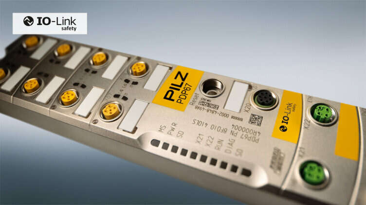
In this article, Pilz lent us a prototype Safety IO-LINK Master PDP67 PN 8FDIO 4IOLS, which we will connect to a Siemens CPU to build a simple system as well as a small introduction to IOLINK and IOLINK Safety.
Let’s enjoy FA.
Thanks!
This article was made possible by the loan of equipment from Pilz Japan. Thank you very much.
PILZ
PILZ supports factory automation sites as a total solution supplier with solutions in safety and automation technology, guaranteeing the safety not only of people, but also of machines and the environment, and how safely machines and equipment can be operated. Pilz has 42 subsidiaries and branch offices worldwide and is active in various fields such as packaging, automotive industry, robotic applications, as well as wind power and railroad technology.

Office:
ピルツジャパン株式会社
〒222-0033
横浜市港北区新横浜3-17-5
いちご新横浜ビル 4階
HP
Before you start..
Before I start the actual article, there are some thoughts on IO-Link Safety after I tested it.
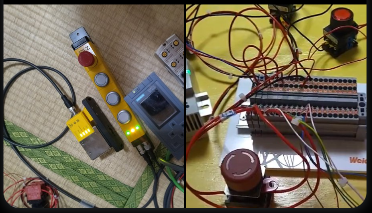
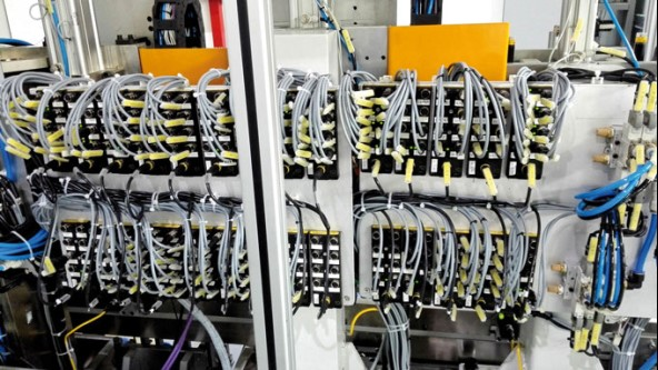
- It makes wiring very easy. Even an amateur like me can wire it neatly. It is easy to do it by communication. Also, when actually operating the system, I expect that wiring man-hours and mistakes will be greatly reduced.
- The network network settings for IO-LINK Safety are not much different from the basic CIP Safety/Profisafe IO Block settings.
- The ability to use one Port as IO-LINK Safety, IO-LINK, or DIDO eliminates wasted module selection time for the designer
- The safety communication setup is a bit more involved.
- I feel that IODD File is a MUST when using IO-LINK Safety.
- How far we can go with multi-vendors will be an issue for the future.
- I think M12 assembly connectors are going to sell well in the future.
Also, here is an article about the Pilz door lock PSEN sl-2 ml used in this article.
PDP67 PN 8FDIO 4IOLS?
PDP67 PN 8FDIO 4IOLS (8 Safety In/Out, 4IOLINK Safety Port) Device with IO port and IO-Link safety port for use in harsh industrial environments up to IP69K protection class, connecting systems to PROFINET with PROFIsafe profile PROFIsafe profile to connect the system to PROFINET.
Also, the PDP67 PN 8FDIO 4IOLS used in this article is still an unreleased prototype as of September 2024; when the PDP67 PN 8FDIO 4IOLS is actually released, specifications and tools may change significantly, so please contact PILZ for the price of the module.
IO-Link
IO-Link is a type of digital communication protocol used in the field of industrial automation, primarily intended to facilitate communication between field devices such as sensors and actuators and control systems (plant controllers and PLCs). It is designed so that devices are compatible and a wide range of industrial devices can be seamlessly connected.
Here is a little about IO-Link before we start talking about IO-Link Safety.
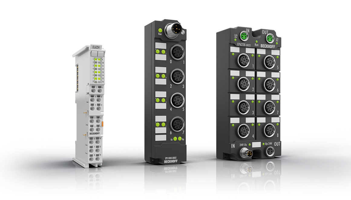
IO-Link Master
The IO-Link master establishes the connection between IO-Link devices and the automation system. As part of a peripheral system, the IO-Link master can be installed in the control cabinet or directly in the field as a remote I/O with protection class IP65/67.
IO-Link masters communicate via various fieldbus or product-specific backplane buses; an IO-Link master can have multiple IO-Link ports (channels), to each of which IO-Link devices can be connected (point-to-point communication).
In other words, IO-Link is a point-to-point communication and not a fieldbus.
The IO-Link port of the master can be operated in the following operating modes.
- Inactive IO-Link ports cannot be used.
- IO-Link Manual IO-Link master only accepts IO-Link devices corresponding to the configured “Vendor ID” and Device ID.
- IO-Link Autostart IO-Link Master accepts all connected IO-Link devices.
- Digital Input (DI) The IO-Link port acts as a standard digital input.
- Digital Output (DO) IO-Link ports operate as standard digital outputs.
IO-Link Device
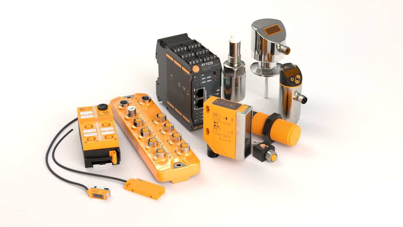
IO-Link devices are field devices designed to communicate using the IO-Link protocol. These devices include sensors, actuators, and other types of equipment used in industrial automation, building automation, and process control systems.
IODD
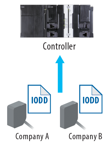
IODD and Engineering Each device has an electronic device description called an IODD file (IO Device Description).
IODDs contain a variety of information for system integration.
- Value ranges and default values for device parameters
- Identification, process and diagnostic data
- Device Data
- Device image Device image
- Manufacturer’s logo
The structure of the IODD is the same for all devices from all manufacturers. This guarantees the same processing in all IO-Link devices, regardless of manufacturer. However, there are two different IODD versions for devices that support both V1.0 and V1.1 functionality.
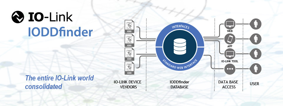
IODDfinder
IODDfinder is a centralized, manufacturer-independent IODD database. It provides the latest IODDs from device manufacturers and provides users with a platform for information and downloads.
https://ioddfinder.io-link.com.
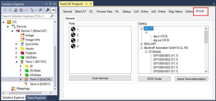
IO-Link Configuration Tool
A configuration tool is required to configure the IO-Link system, and the IO-Link configuration tool of the master manufacturer can read IODDs. the most important tasks of the IO-Link configuration tool are:
- Assignment of devices to ports on the master
- Address assignment of ports within the address range of the master (I/O addresses for process data)
- Parameterization of IO-Link devices
IO-Link Safety?
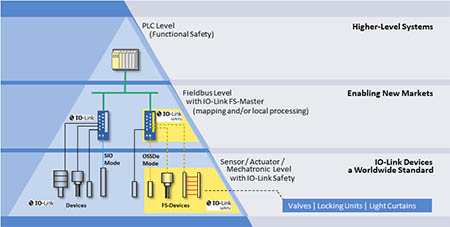
IO-Link Safety is based on the IO-Link technology standardized in IEC 61131-9 and specifies a digital single point interface (SDCI) for sensors, actuators and mechatronics. It extends the traditional switched inputs and outputs defined in IEC 61131-2 to include point-to-point communication links using coded switching. IO-Link Safety extends IO-Link to provide an additional safety communication layer on both the master and device side, making them “FS Master” and “FS Devices”.
Basic
IO-Link Safety is a new option to extend automated machines and systems with functionally safe components and communication via IO-Link. It is the addition of FS Master and FS Devices to the Masters you are all familiar with. The advantage is that the IO-Link connection and transmission technology is still available, making it easier to implement safety functions.
Universal Safety
From FS Master…
- FS-Master is built on top of the standard IO-Link Master and provides additional safety communication.
- Conventional switching safety sensors with OSSD are compatible with FS-Master.
- Non-safety IO-Link devices can also be connected to FS-Master.
From FS Devices…
- The FS-Device can be a safety sensor, an actuator, a combination of these, or a safety mechatronic.
- Instead of using different safety devices for multiple safety buses, only one type of FS-Device is needed for the global market.
- IO-Link Safety is independent of the upper system.
Smart Safety
- FS-Devices can be parameterized with the IO-Link tool (IODD) to reduce the variety of types, for example
- IO-Link Safety meets the growing demand for cost-effective and measurable safety sensors.
- FS-Devices can be made ultra-compact
- Enables simple device replacement (FS-Device) without tools, even with safety
- Unauthorized connections can be detected (Port Detection)
- IO-Link Safety provides the safety sensor with a transition from switching mode (OSSD) to safety communication.
- FS-Devices can be parameterized in the IO-Link tool for use with safety digital inputs of the Safety Fieldbus (OSSD)
Easy Safety
- IO-Link safety is as lean as IO-Link
- Power supply is in the same cable
- Device Description and “Dedicated Tool” for FS-Device (IODD) are available directly in the IODD-Finder Server.
- Safety function planning simplified by IODD parameter specifications (e.g. determination of reaction time)
Why?
So why use IO-Link Safety? IO-Link Safety is important for compact I/O systems because it allows the FS-Master to operate any version of FS device it wants on its respective port, whether it is a sensor, actuator, or complex mechatronics. This enables new safety applications, for example, linking the local safety logic of the FS-Master with the safety functions of a higher-level system. It also simplifies the transmission of safety and non-safety related data, such as the operation of devices with emergency stop functions.
OSSDe and SIO
IO-Link Safety specifies that the secondary signal line (“Pin 2”) of the IO-Link together with the primary signal line (“Pin 4”) shall act as a redundant signal. This standardized version is OSSDe.
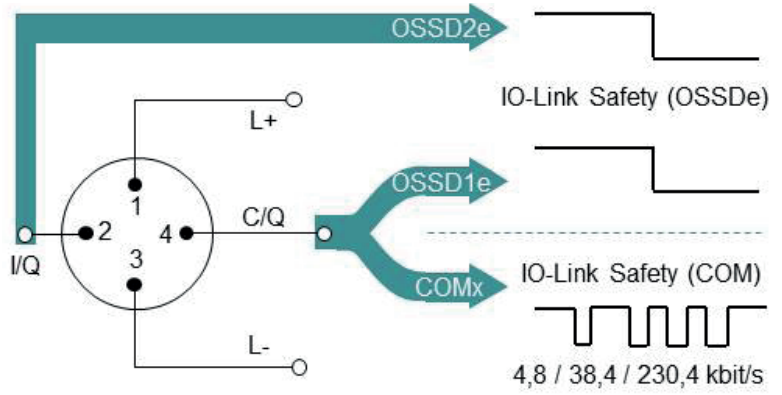
In addition, safety communication is performed at all three transmission rates, COM1, COM2, and COM3, using only the primary signal line.
IO-Link Safety Theory
Safety communication via the standardized fieldbus protocol (FSCP) follows the “black channel” principle. This fieldbus, in this case PROFINET with PROFIsafe, is used as a transmission channel for special messages consisting of safety data and additional safety codes. The purpose of the safety code is to reduce the residual error probability of the data transmission to the level required by safety standards such as IEC 61784-3. The messages are processed in the safety communication layer (SCL) on the fieldbus.
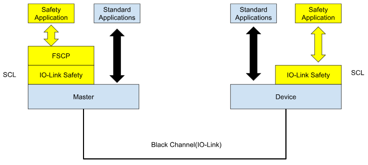
FSCP
FSCP is a functional safety communication profile (e.g. PROFINET with PROFIsafe profile).
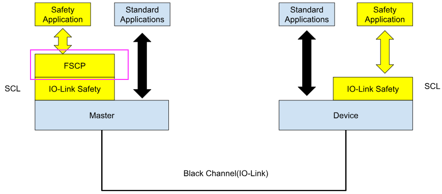
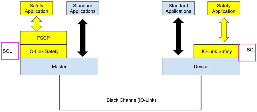
SCL
SCL=Safety Communication Layer This is the security communication layer.
Stack
The stack is a dynamic data structure based on the “Last In First Out” (LIFO) principle. The last element added is processed first.
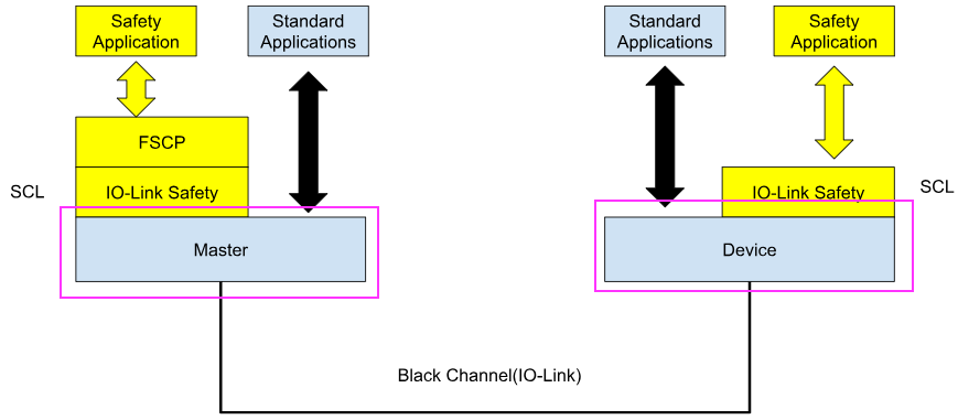
Black Channel
Most FSCPs follow the “Black Channel” principle, where the existing fieldbus is used as a carrier for special types of messages containing safety process data and additional safety codes. The purpose of the safety codes is to reduce the residual error probability of data transmission to the level required by safety standards such as IEC 61784-3. The processing of these messages is performed by the Safety Communication Layer (SCL) on the fieldbus.
IO-Link Safety Communication
Three main characteristics of secure communications have been determined
- Timeliness (data arrives on time)
- Time prediction with acknowledgement by watchdog timer that is restarted each time a new IO-Link Safety message arrives
- Authenticity (data from correct sender)
- Authentication at protocol startup: FS-Device is connected to the correct FS-Master (unique connection ID in FSCP) and the correct FS-Master port (“PortNum”). Only the port number is checked cyclically.
- Cyclic Redundancy Check (CRC) signature over process data and safety code.
- Integrity (data is up-to-date and correct)
- The FS-Master uses a repeating 3-bit counter value, e.g., for numbering messages between the FS-Master and the FS-Device; the FS-Device has its own counter, synchronized at the start of the protocol, and responds with a 1’s complement value.
Many errors can occur during message transmission between FS-Master and FS-Device. The following safety measures have been selected so that the residual error probability of the transmission is reduced to the level required by the relevant standards such as IEC 61784-3 or higher. IO-Link safety communication can therefore be used for safety functions up to SIL 3 or PL e.
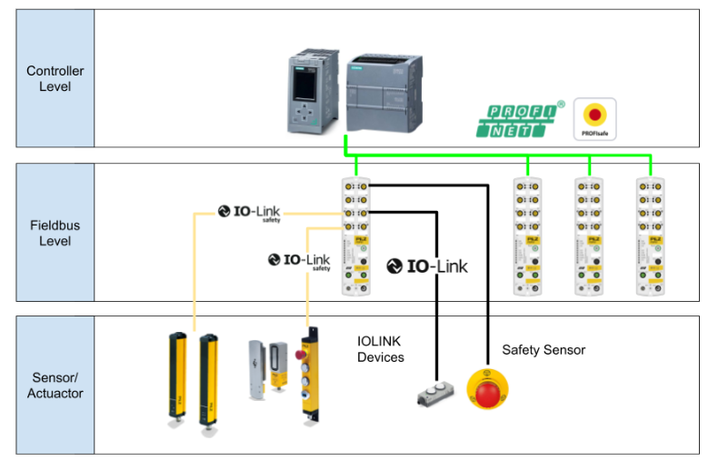
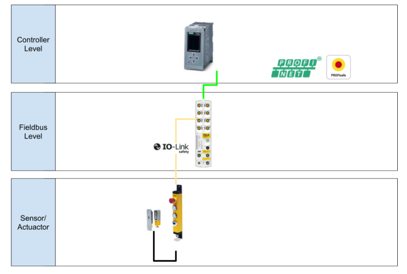
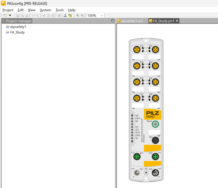
IO-Link Safety System Overview
With IO-Link safety systems, it is important to be able to communicate safety directly to the field.As IO-Link master, PDP67 PN 8FDIO 4IOLS handles communication with the host controller via PROFINET/PROFIsafe and is configured as shown in the figure below.
Shared Device
Up to two PROFINET controllers can be assigned to each PDP67 PN 8FDIO 4IOLS (2024-09 prototype specification).
More about Shared Device:
PROFINET MRP (Media Redundancy Protocol)
PDP67 PN 8FDIO 4IOLS supports PROFINET MRP with up to one MRC ring (2024-09 prototype specification).
Implementation
Configuration
This is the hardware configuration for this project, using S71516F as the controller since PDP67 PN 8FDIO 4IOLS can support Profinet and Profisafe protocols.
Profisafe and Profinet communication between PDP67 PN 8FDIO 4IOLS and S71516F.
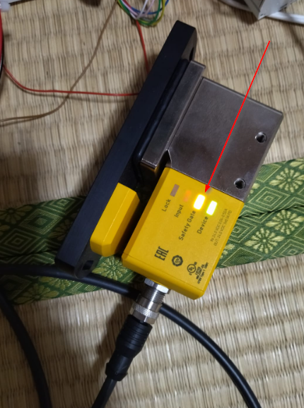
This article also connects to Pilz’s prototype Safety IO-LINK device PITgatebox. The Safety IO-LINK device PITgatebox has a 4-Pin and 8-Pin M12Connector.
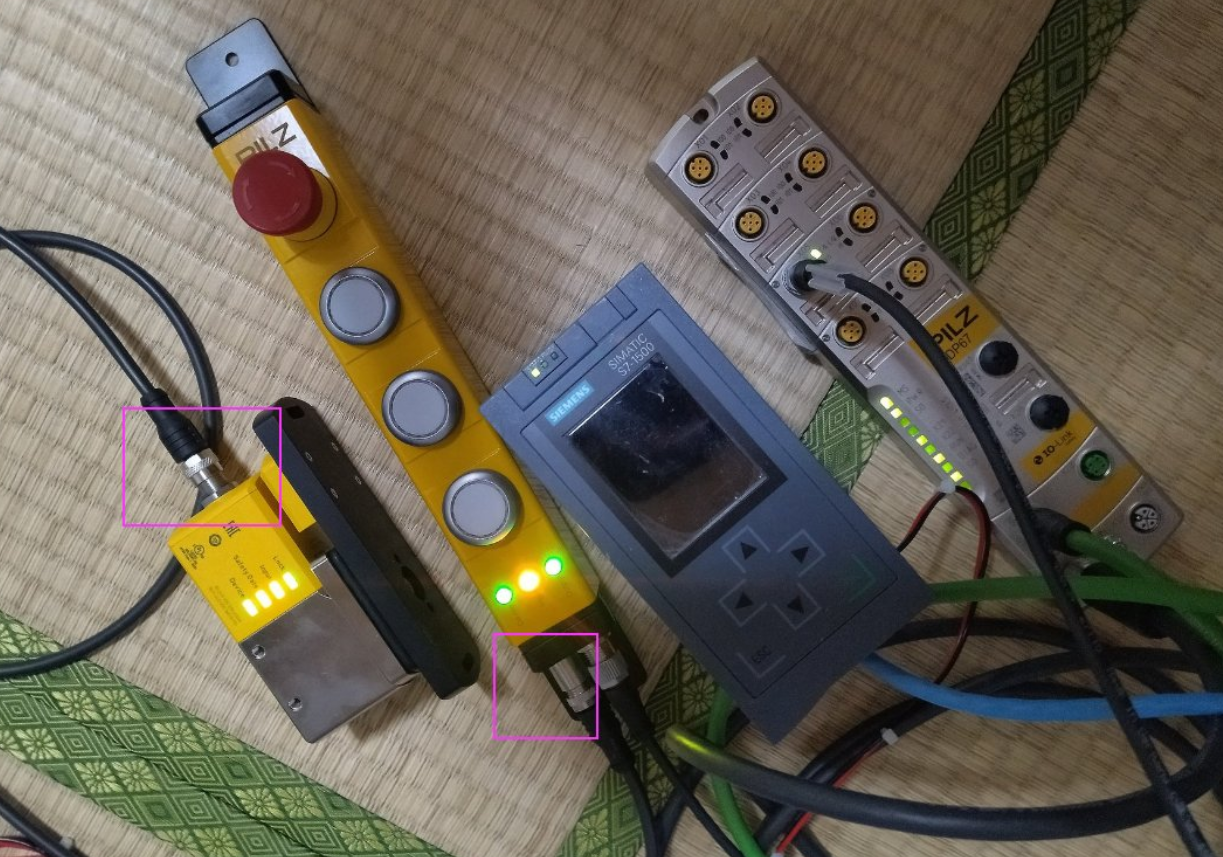
The 4Pin Connector of course connects to the PDP67 PN 8FDIO 4IOLS IO-LINK Safety, but the 8Pin Connector connects directly to the Pilz door lock. I am not sure if this is the correct usage, but it can be used for door lock-unlock operation, etc.
Siemens Side
Let’s start from the Siemens side.
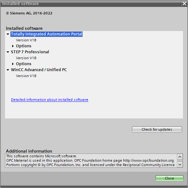
TIA Version
Here is the Version of TIA used in this article.
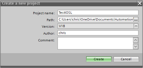
New Project
We will create a new project.
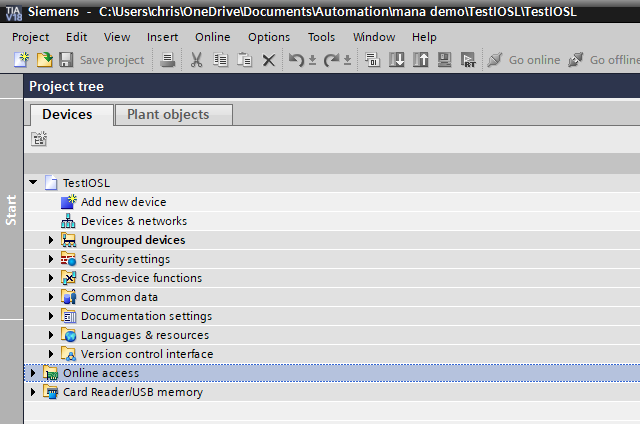
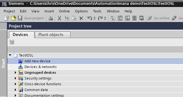
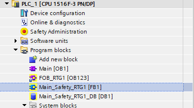
Add New PLC
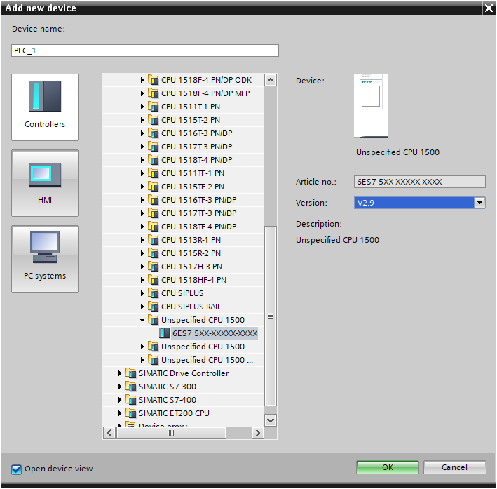
Click “Add new device” to add the S71516F used in this article.
This is the CPU selection screen for the project.
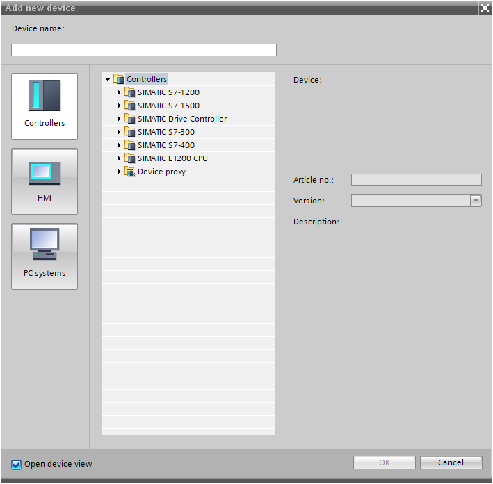
This time, since we want to connect directly to the actual device and upload CPU information, select Unspecified CPU 1500 >OK to proceed.
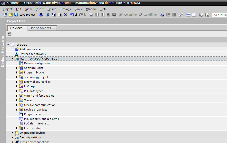
Done!Projects have been added.
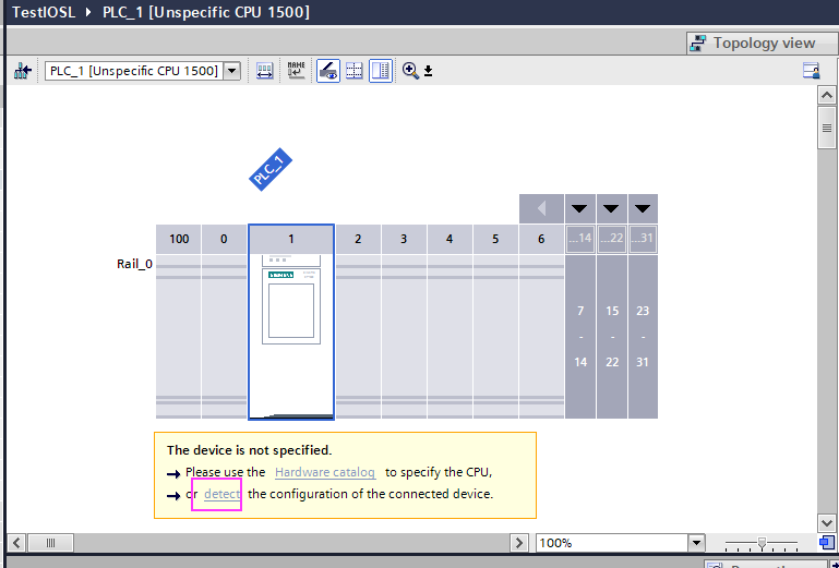
Detect
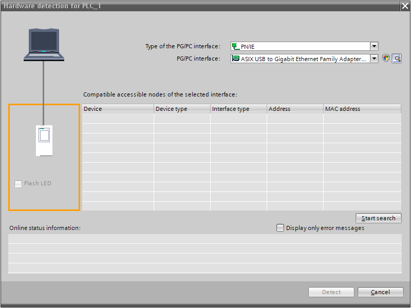
Switch TIA to Network view, click on Detect, and search for S7151F in the network.
Click Start Search.
Done!Finally, click on Detec and Upload CPU information.
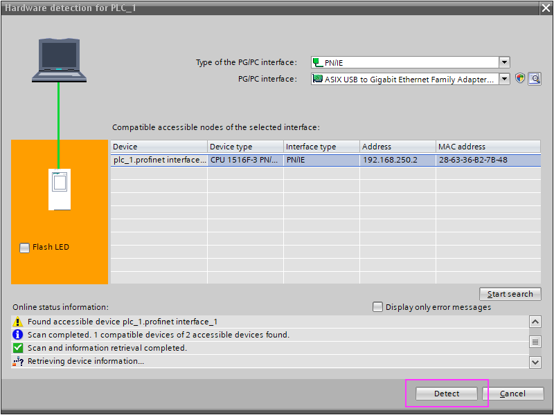
Proceed with Connect.
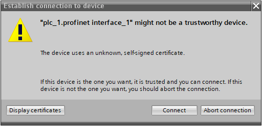
Security Settings
Various security settings have been added to the project and CPU since TIAV16, so make those settings as well.
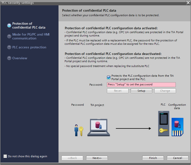
Proceed without Protects.
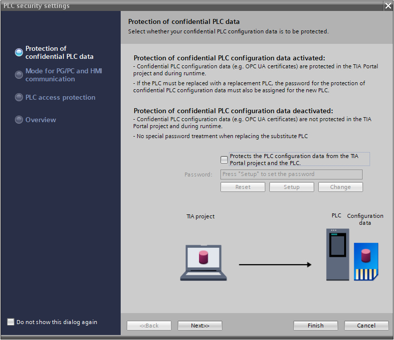
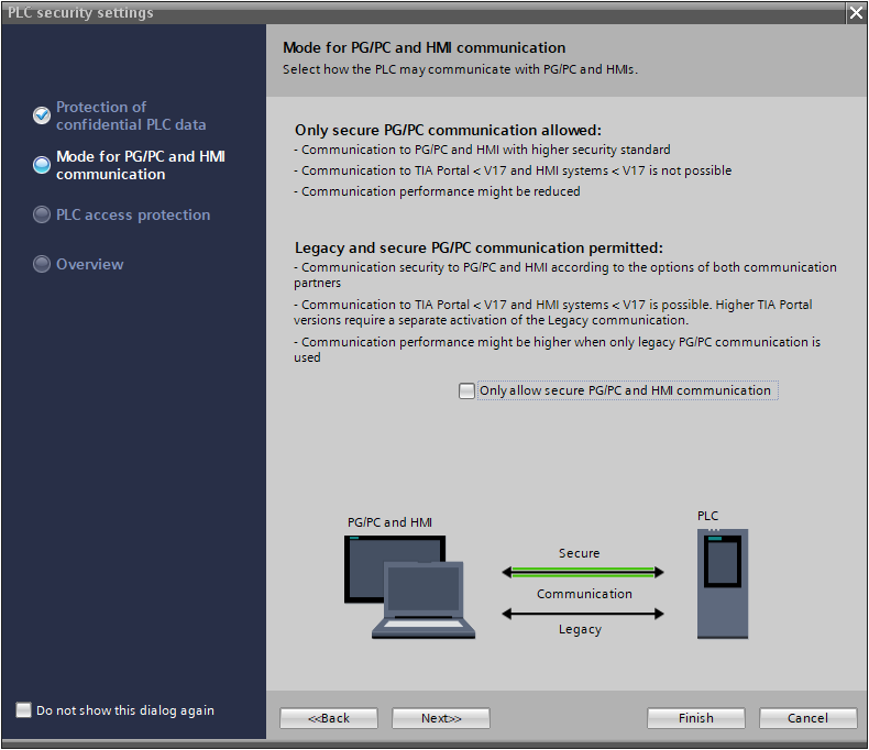
The next step is to set up the security connection.
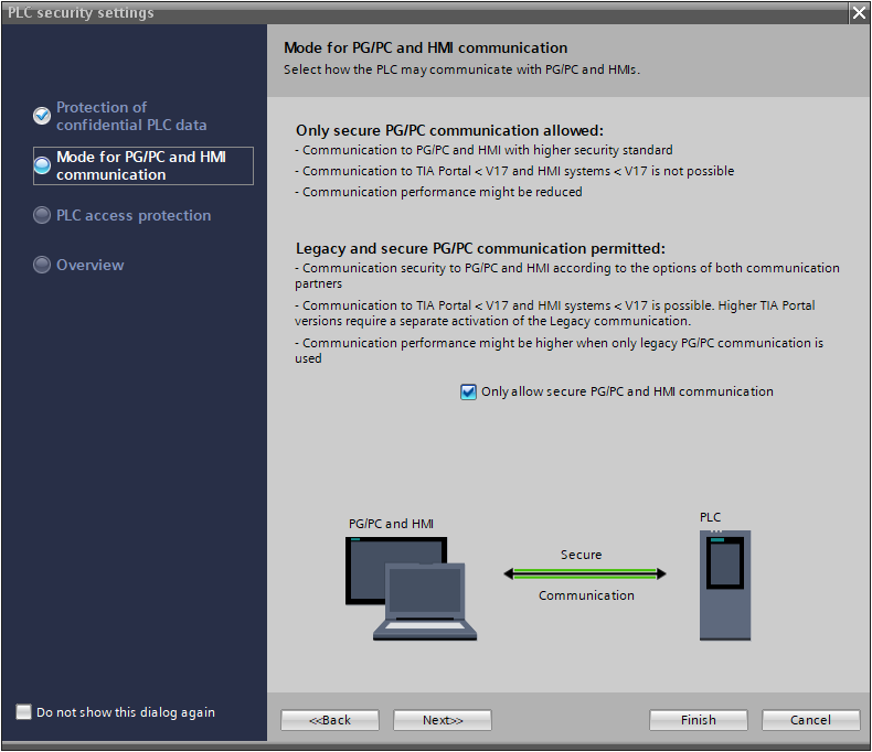
Remove the Checkbox and proceed with Next.
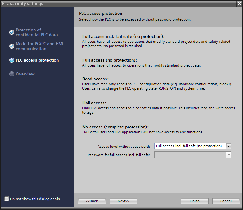
Set the Password and other settings for PLC access.
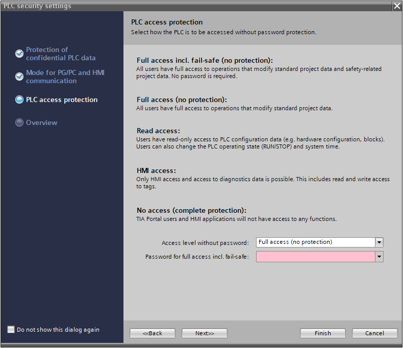
Set “No Password” and proceed with “Finish”.
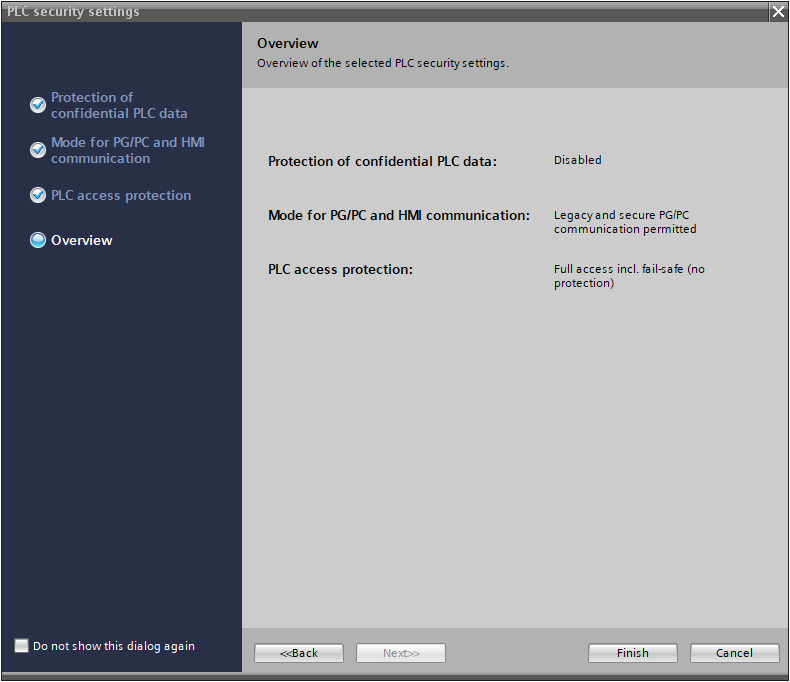
Review all settings to make sure they match the application and proceed with Finish.
Result
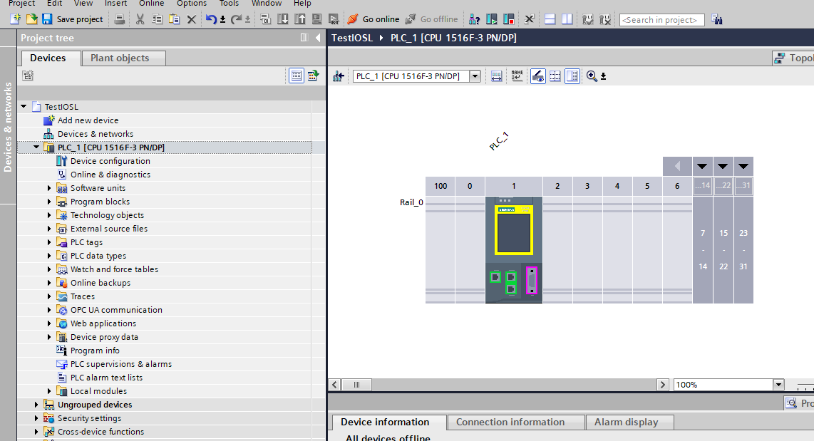
Done!CPU is added in your project.

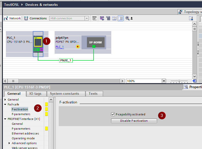
Enable Profisafe
Set Fail-safe>F-activation>Enable F-Activation to enable Profisafe on the CPU used this time.
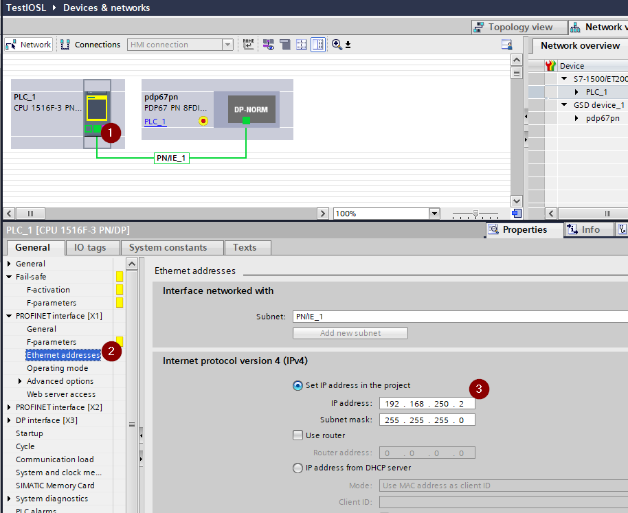
Ethernet Address
To set the IP address of the CPU, use PROFINET Interface>Ethernet address to match the application.
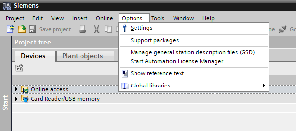
Install GSDML File
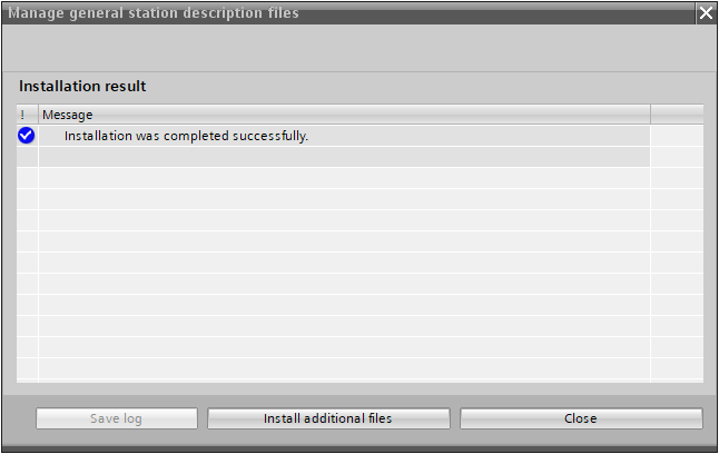
To install the GSDML File for PDP67 PN 8FDIO 4IOLS, click Options>Manage general station description files (GSD).
Set the Folder that contains the GSDML File in Source Path.

Done!
Configure Profinet Network
The next step is to build the Profinet network.
ADD PDP67 PN 8FDIO 4IOLS
We have just installed the GSDML File for PDP67 PN 8FDIO 4IOLS, so go to Catalog>PROFINET IO>PDP67 and select PDP67 PN 8FDIO 4IOLS and add it to your project.
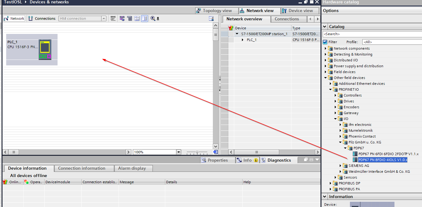
Done!PDP67 PN 8FDIO 4IOLS has been added.
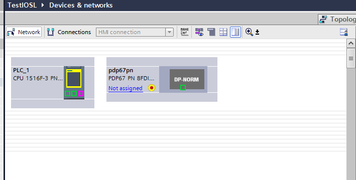
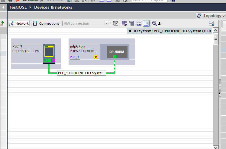
Assign Profinet Network
To install the same Profinet network with PDP67 PN 8FDIO 4IOLS and CPUs, let’s click Not Assigned and select the PROFINET network.
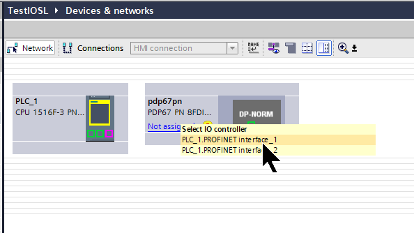
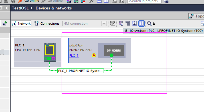
Done!
Configur Devices
Now double-click on the device you just added to set the parameters for PDP67 PN 8FDIO 4IOLS.
TIA automatically switched to Device view.
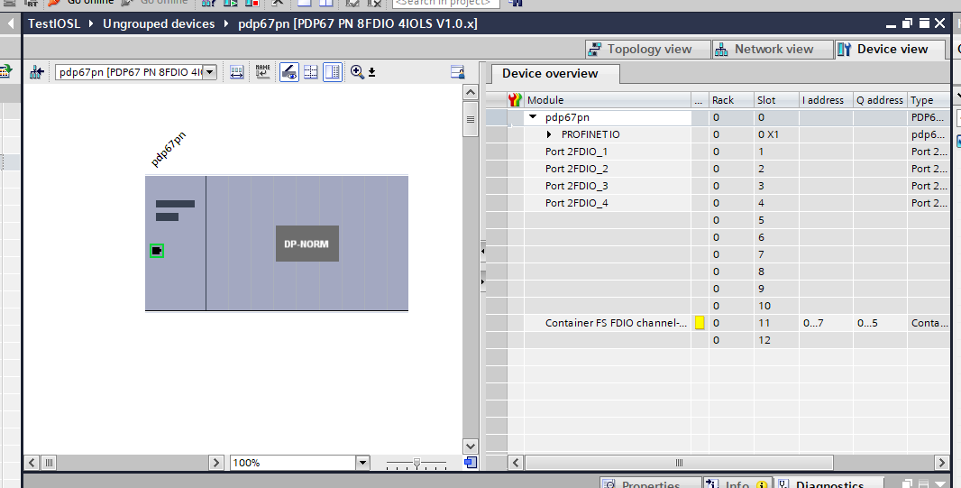
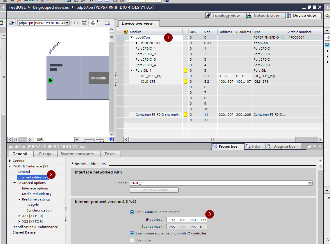
Slots
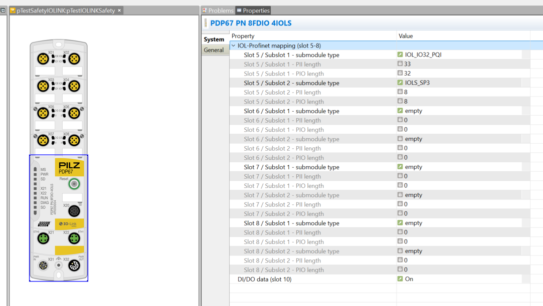
Slots 1-4 are IO only and Slots 5-8 can be configured as IO-Link or Safety IO-Link.
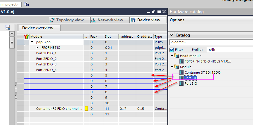
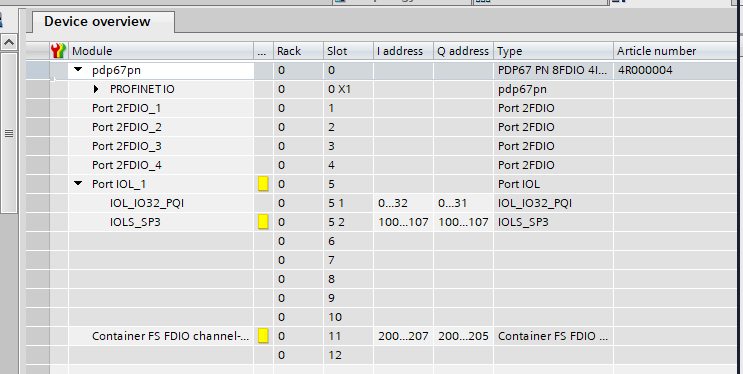
Slot 5 is configured as IO-Link Port as shown in the figure below, Slot 5-1 is installed as IO-LINK data and Port 5-2 as Safety IO-Link.
- IOL_IO32_PQI = 32 bytes of input data + 1 byte of port information + 32 bytes of output data
- IOLS_SP3 = 3 bytes of input data + 3 bytes of output data
It is important to note that submodule 1 always sets up non-secure IOL data and submodule 2 always sets up secure IOLS data.
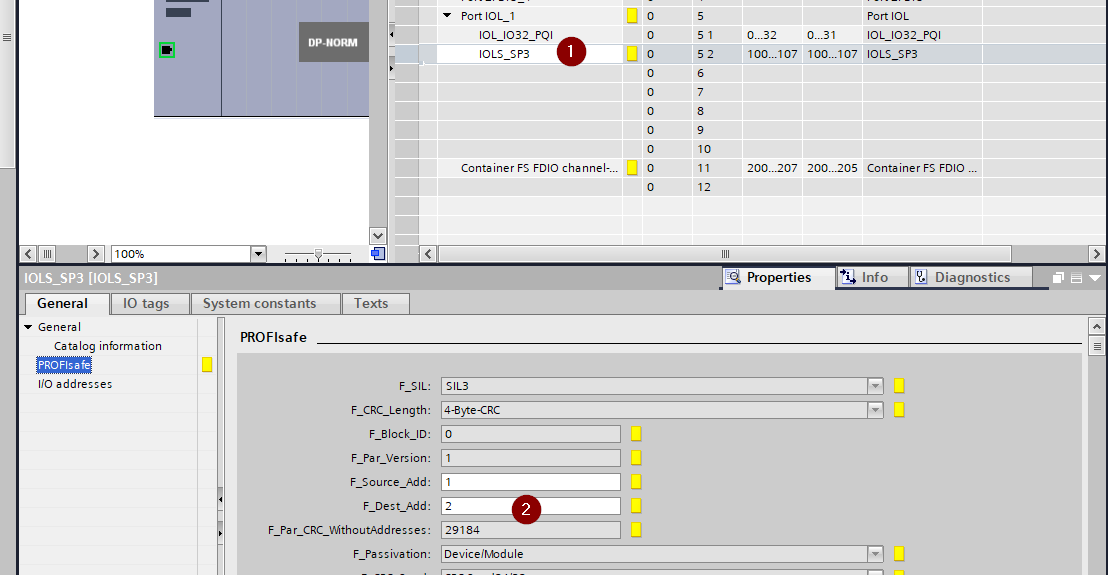
Profisafe Address
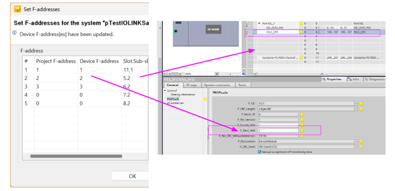
Since we are doing Profisafe secure communication, we need to set the Profisafe address. The Profisafe address for Slot5-2 is set to 2.
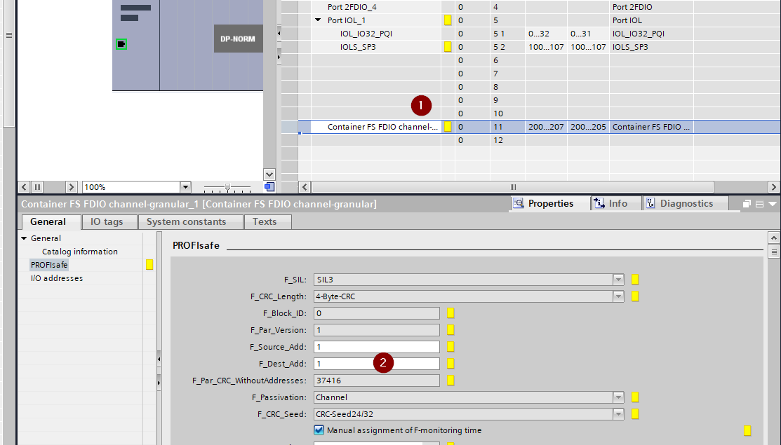
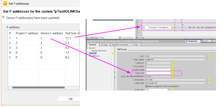
The Profisafe address for Slot 11 will be placed in 1.
Etherenet Address
Set the IP address of PDP67 PN 8FDIO 4IOLS in PROFINET>Ethernet.
Assign IP Address
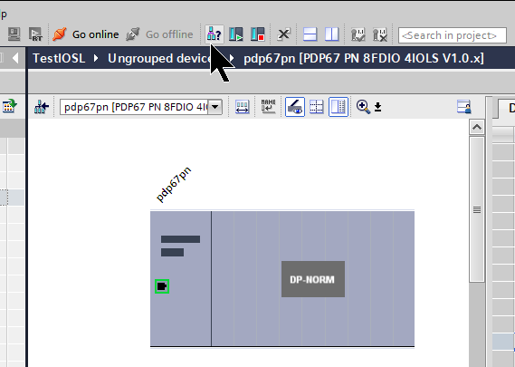
IP allocation to the Profinet Device via Profinet Master may not be possible until the PDP67 PN 8FDIO 4IOLS installation is completed,Click the button below to search for PDP67 PN 8FDIO 4IOLS in TIA.
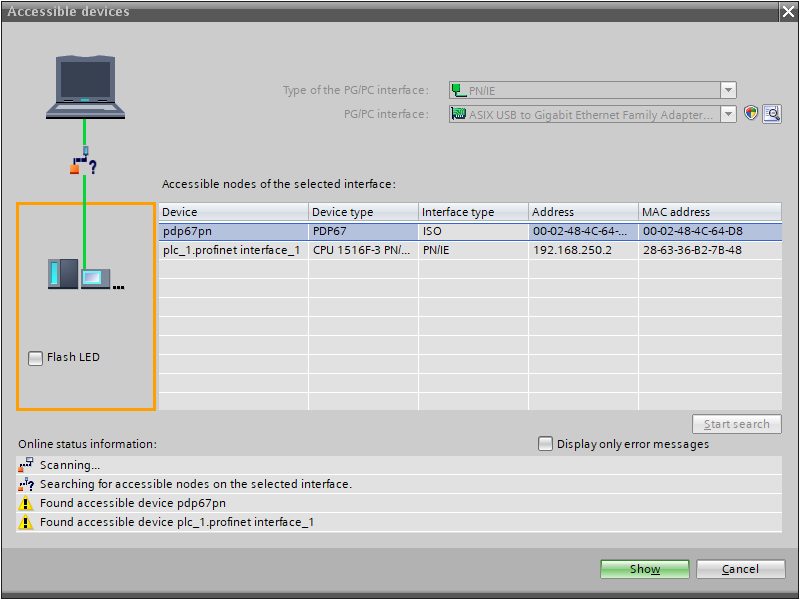
Click Start Search to search for Profinet devices in the network.
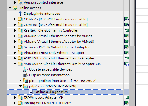
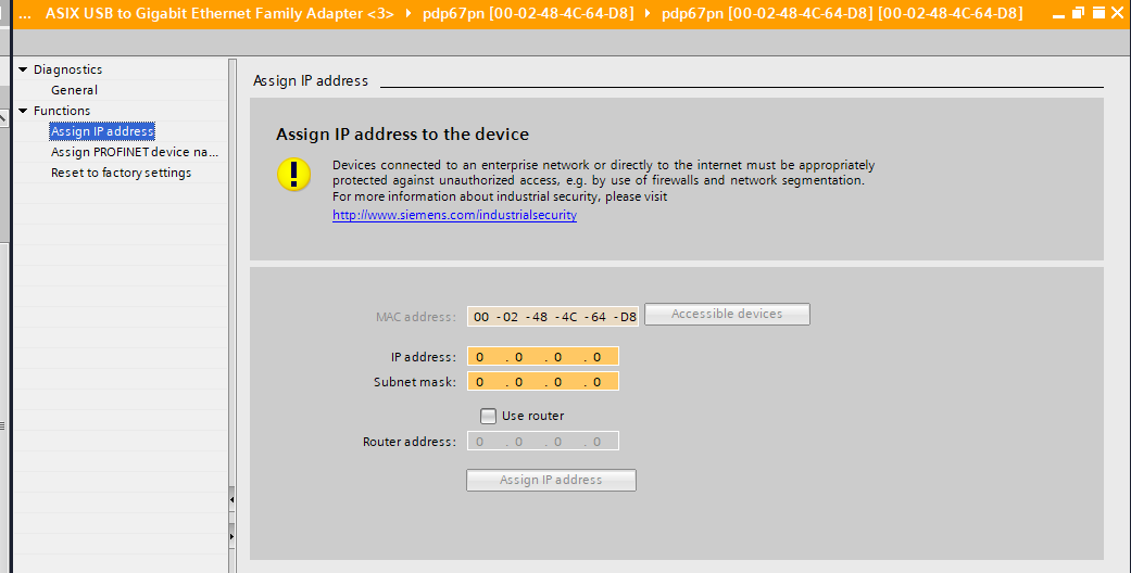
Click on Online & diagnostics.
Let’s set the IP address under Functions>Assign IP Address.
Assign Name
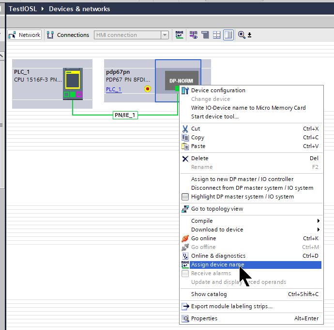
Next, to set the device name for the PDP67 PN 8FDIO 4IOLS via TIA, right click>Assign device name.
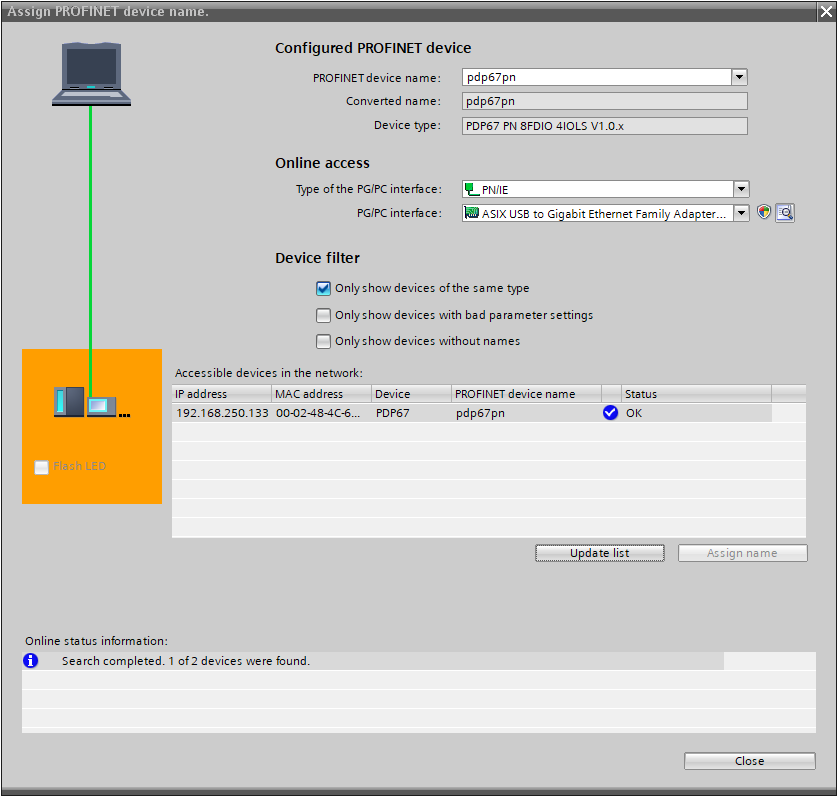
Search for the Profinet device in the Update list and assign a Profinet device name in Assign name.
Tags
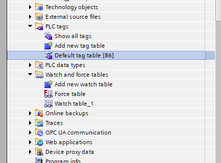
Open the PLC Tags>Tag Table to define your Tags.
The IO-LINK Safety slave used in this article is still a prototype, so some of the mappings cannot be finalized yet.
| PITgateboxButton1Status %I0.7 Bool PITgateboxButton2Status %I2.7 Bool PITgateboxButton3Status %I4.7 Bool PITgateboxLockInPosition %I9.0 Bool PITgateboxLockStatus1 %I11.0 Bool PITgateboxSafetyRelease1 %I100.0 Bool PITgateboxSafetyRelease2 %I100.1 Bool PITgateboxSafetyESTOP %I100.2 Bool PITgateboxSetLockingTrigger %Q0.0 Bool PITgateboxSetLockingDevice %Q2.0 Bool PITgateboxButton1LEDFlash %Q3.7 Bool PITgateboxButton2LEDFlash %Q5.7 Bool PITgateboxButton3LEDFlash %Q7.7 Bool PITgateboxButton1LEDON %Q9.7 Bool PITgateboxButton2LEDON %Q11.7 Bool PITgateboxButton3LEDON %Q13.7 Bool PITgateboxSafetyPowerOutput32 %Q100.0 Bool PITgateboxSafetyPowerOutput42 %Q100.1 Bool mPDP67SafetyReset %M100.1 Bool |
Safety Program
Create a safety program for a Siemens PLC.
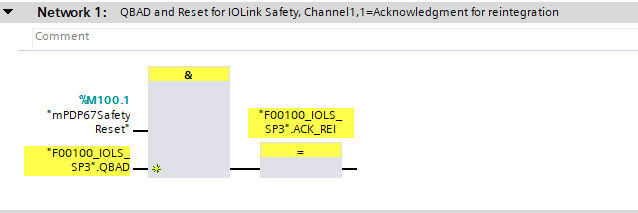
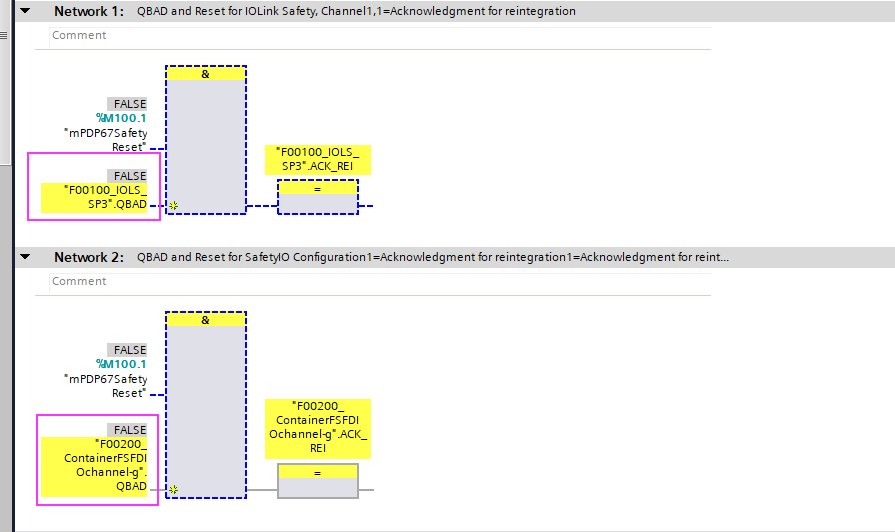
Network1
This one sets ACK_REI to True and resets QBAD when IO-LINK Safety generates a QBAD signal.
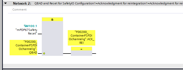
Network2
This one sets ACK_REI to True and resets QBAD when the Safety Container generates a QBAD signal.
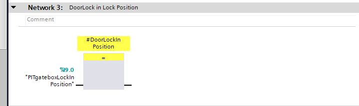
Network3
This one detects that the Safety Gate signal of the door lock has been detected.
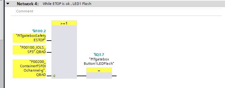
Network4
This one will flash button 1 when an emergency stop is pressed or QBAD occurs again.
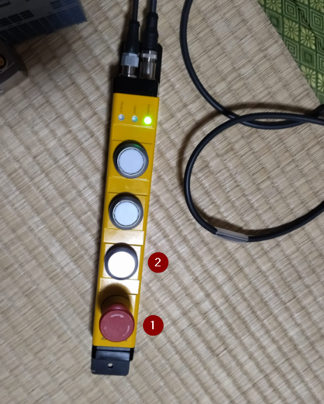
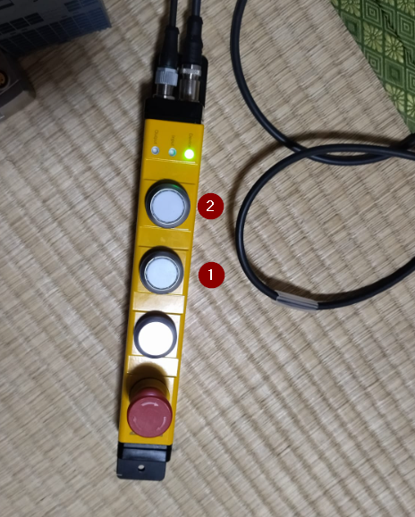
As shown in the figure below, 1 is the emergency stop and 2 is button 1.
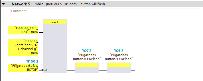
Network5
This one will flash button 2 and button 3 when the emergency stop is pressed or QBAD occurs again.
As shown below, 1 is button 2 and 2 is button 3.
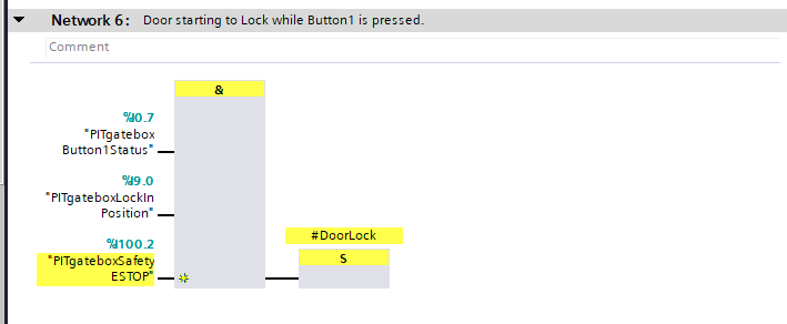
Network6
When the emergency stop is not pressed or the Safety Gate signal is turned on, the door locks when button 1 is pressed.
Network7
This one unlocks the door when button 2 is pressed.

Network8
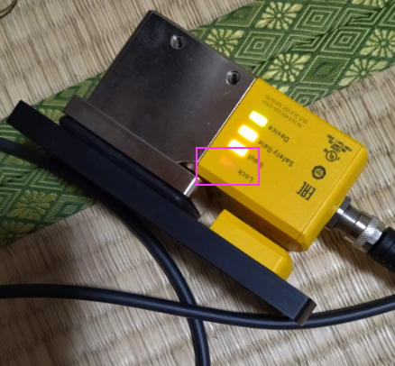
To operate the Lock/Unlock PITGB box, SafetyPowerOutput32/SafetyOutput42 must first be turned on.
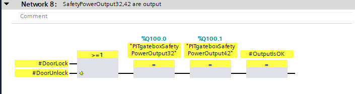
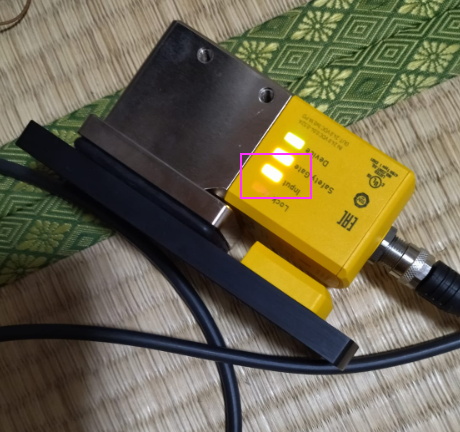
When SafetyPowerOutput32/SafetyOutput42 is turned on, the Input LED of the door lock lights up.
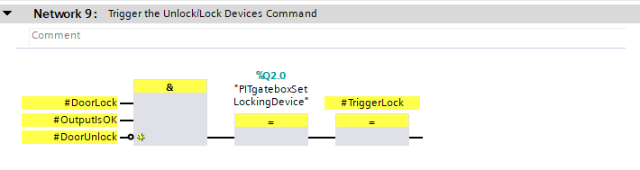
Network9
Turn on the safety output SafetyPowerOutput32/SafetyOutput42 of the PITGB box and Ture or False the IOLINK output of the LockingDevice by the Lock/Unlock command.
- Ture=Ture the IOLINK output of LockingDevice=Door Lock
- IOLINK output of LockingDevice False=Door unlocked
Network10
After turning on the safety output SafetyPowerOutput32/SafetyOutput42 of the PITGB box and setting it to the Lock/Unlock command, Lock/Unlock is performed with the Trigger falling signal.
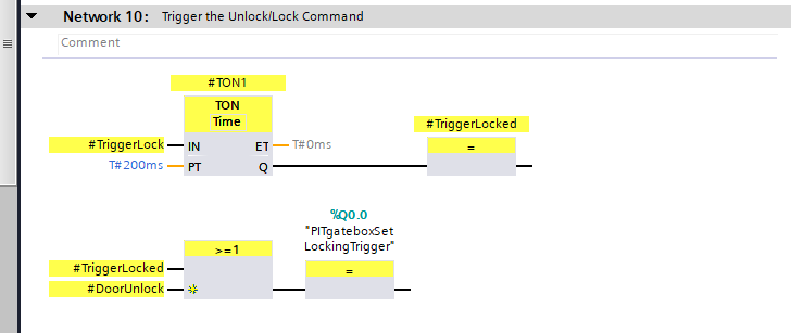
Its Trigger and LockingDevice signal outputs the Lock signal for door lock.
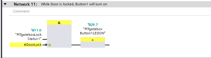
Network11
Button 1 illuminates when the door lock is locked.
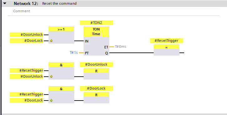
Network12
The last program is to reset the Lock and Unlock commands.
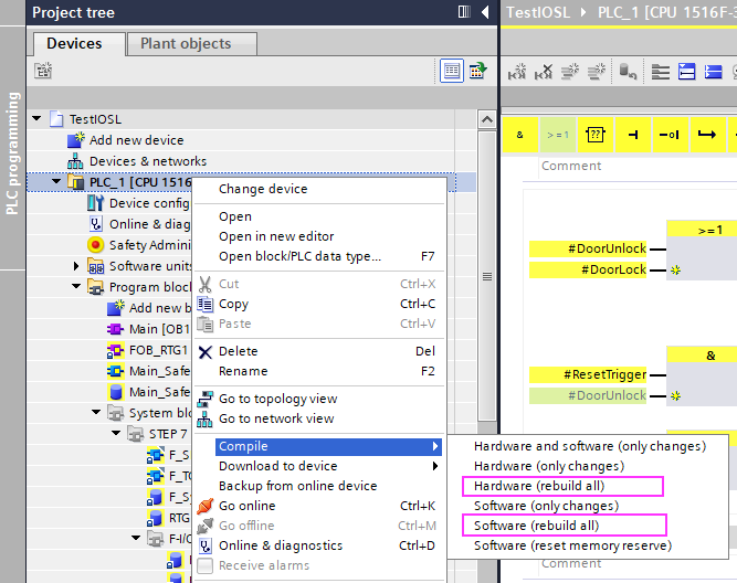
Compile
Right click on PLC>Compile>Hardware(Rebuild all) and Software(Rebuild all) to compile your project.
Download
Download the Hardware Configuration and program to the CPU. This completes the installation on the Siemens side.
Pilz Side
Next we will set up Pilz’s PDP67 PN 8FDIO 4IOLS.
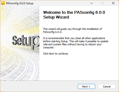
Install Tools
Install the latest PASconfig tool.
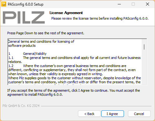
Agree to the license and proceed.
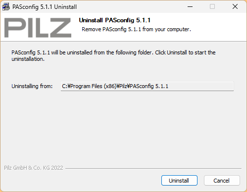
Remove the old PASconfig tool currently installed on your PC.
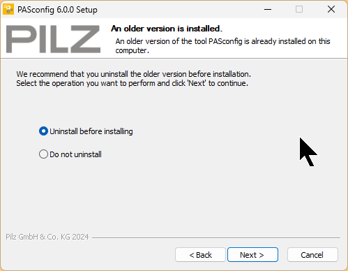
Proceed with Uninstall.
Please wait a moment…
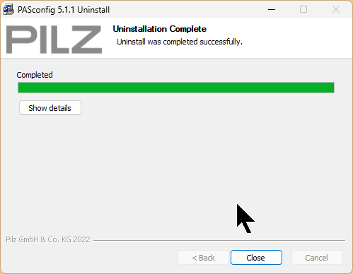
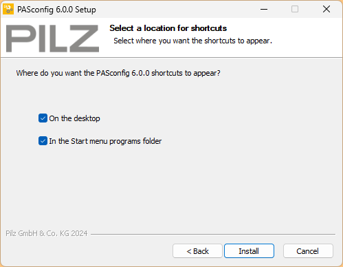
The next step is to set the installation location for the new PASconfig tool.
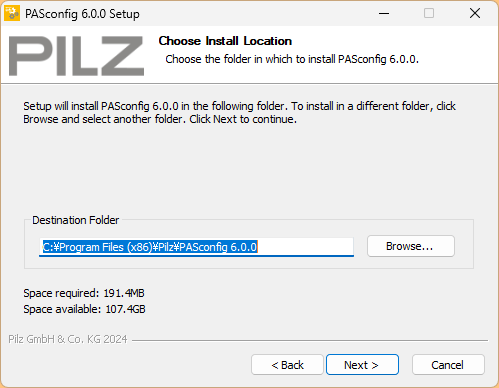
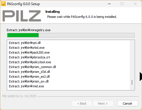
Start installation.
Please wait a moment…
Done!
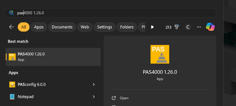
Start the Application!
Start PASconfig 6.0.0.
Done!
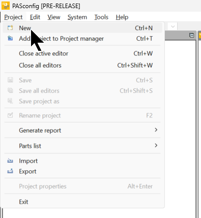
Create new Project
Add a new project with Project>New.
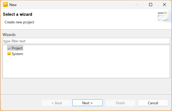
Select Project and press Next> to proceed.
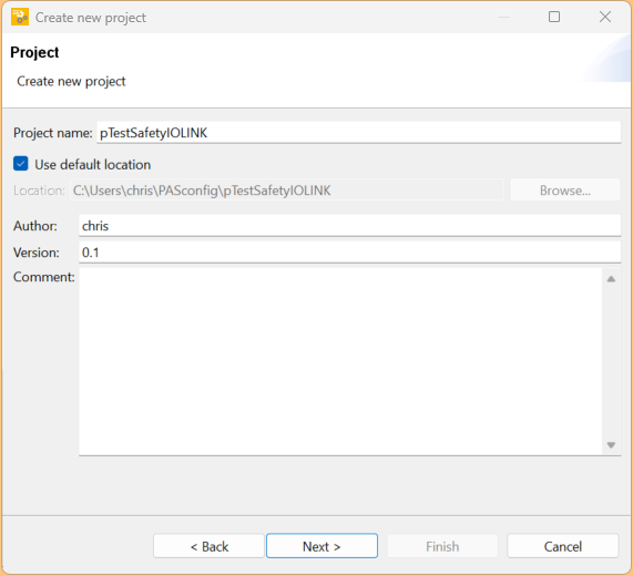
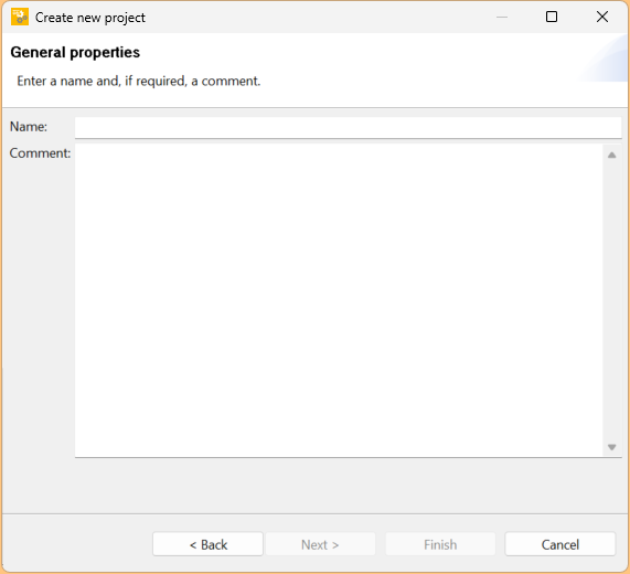
Enter a project name and press Next> to proceed.
The next step is to set the device type for the project.
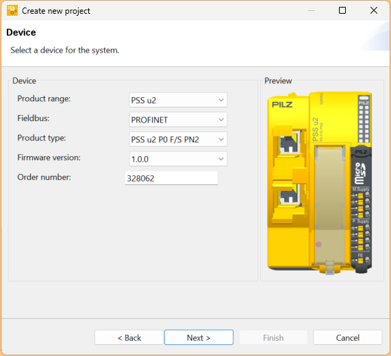
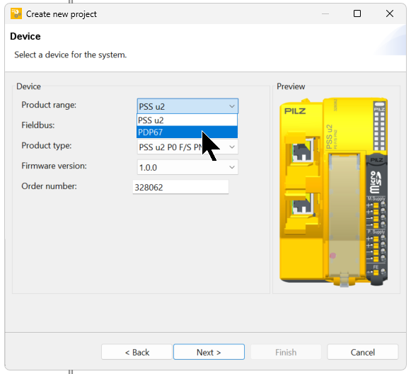
Set PDP67 to Product Range.
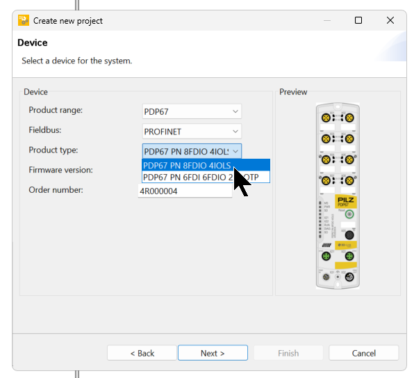
Set Product Type to PDP67 PN 8FDIO 4IOLS and proceed with Next>.
Enter the device name and press Next> to proceed.
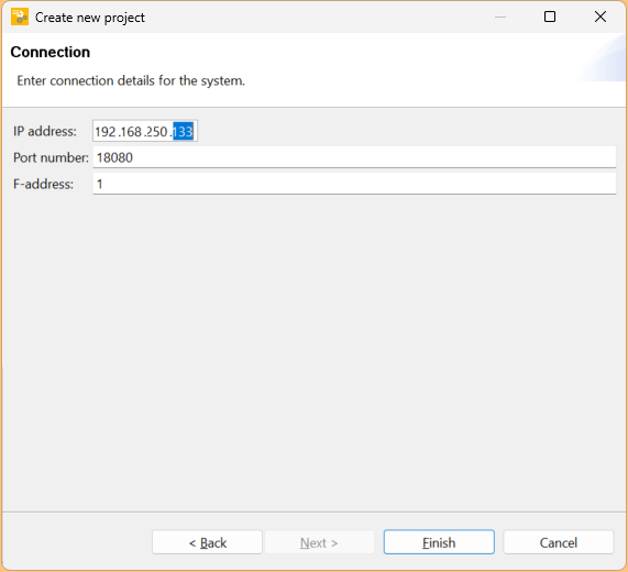
Next, set the IP address and F-Address for PDP67 PN 8FDIO 4IOLS and proceed with Next>.
Done! project has been added.

Configure Slots
Make basic settings for IO-LINK Safety for PDP67 PN 8FDIO 4IOLS Select PDP67 PN 8FDIO 4IOLS and click on the bottom part of the module.
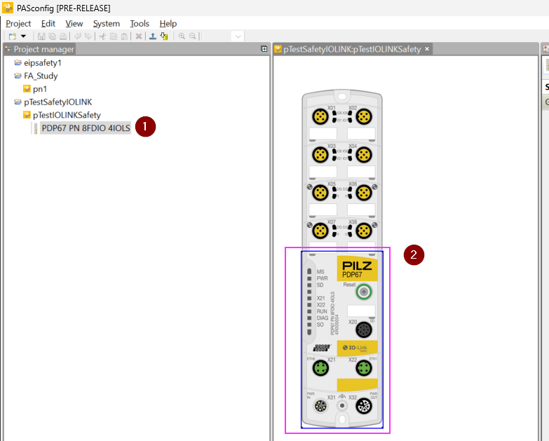
The Property screen appears on the right side of the tool.
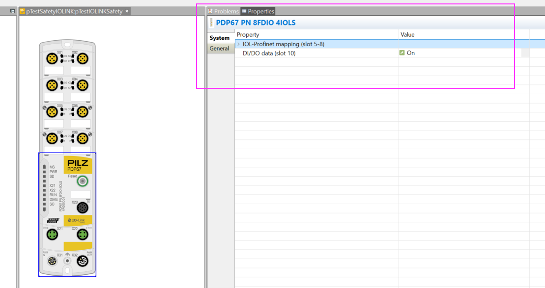
Expand the Property Settings menu and configure Slot settings up to Port5-8.
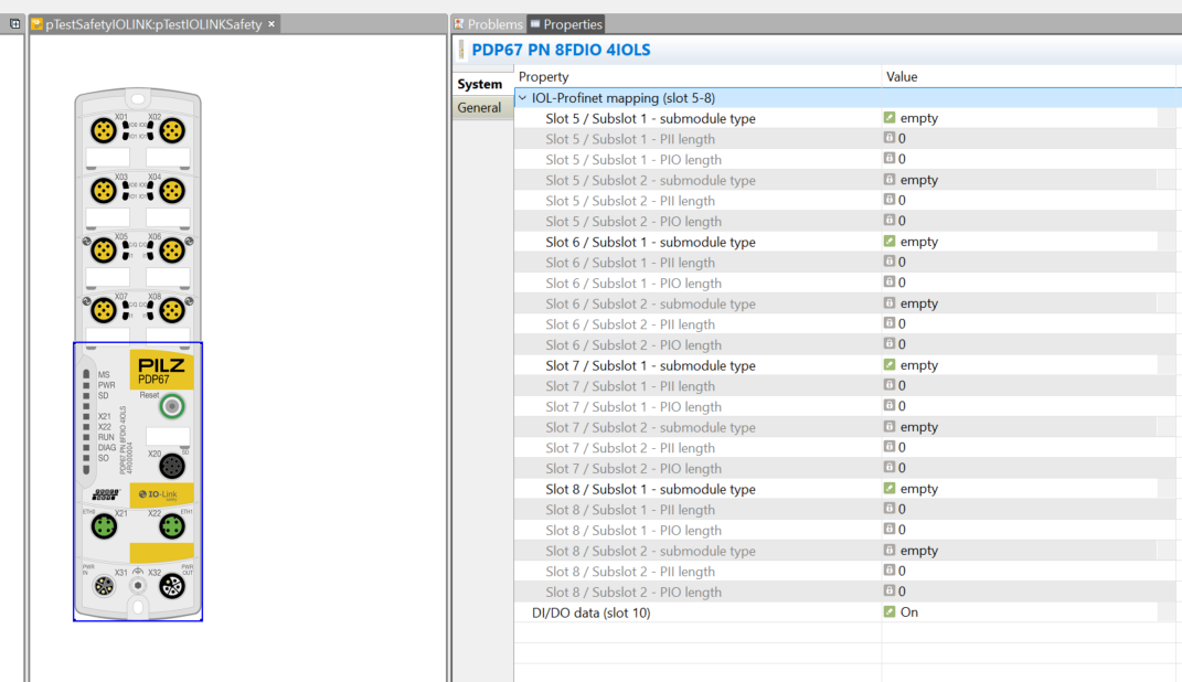
In this case, only Slot 5 was used, so set the Submobule type for Port 5.
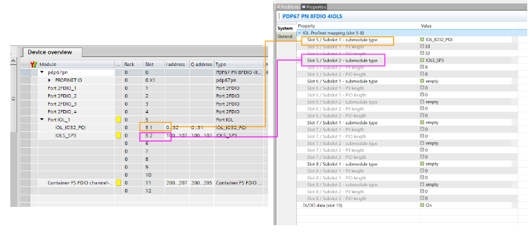
Slots Address
Slot Address corresponds to 5 1 and 5 2 on the TIA side; Slot/Submoule 1 in the Pilz tool becomes 5 1 in TIA, and Slot/Submoule 2 becomes 5 2 in TIA.
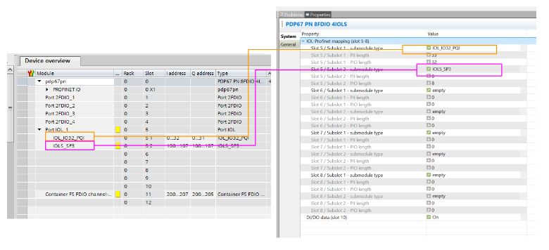
Slots Type
Slot Type should be installed according to 5 1 and 5 2 on the TIA side.
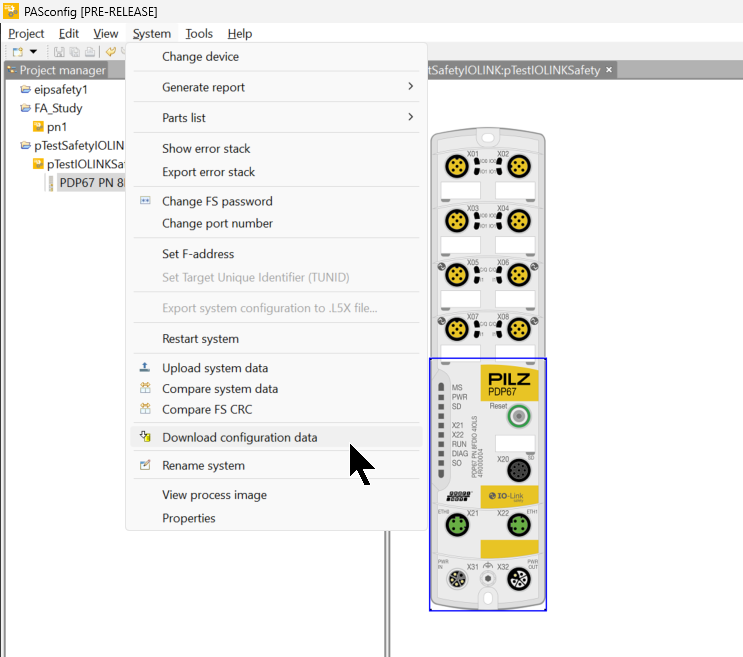
Download Configuration
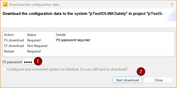
Download the project to PDP67 PN 8FDIO 4IOLS by going to System>Download Configuration data.
FS password is pssu on Default, enter Password and Start download.
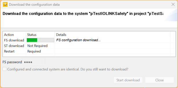
Please wait a moment…
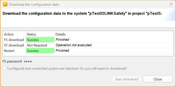
Done!
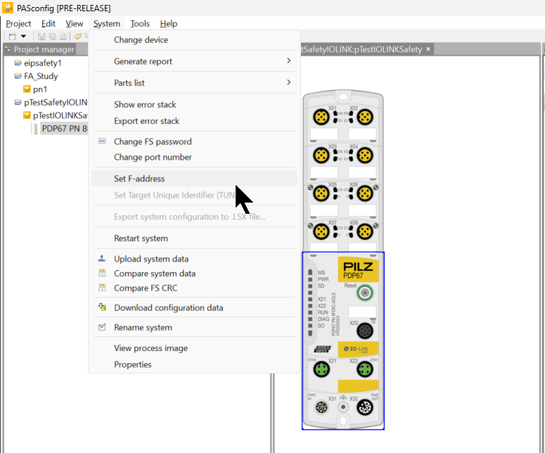
Set F- Address
Now click on System>Set F-address to set the F-address for PDP67 PN 8FDIO 4IOLS.
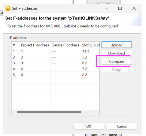
This is the F-Address operation screen.
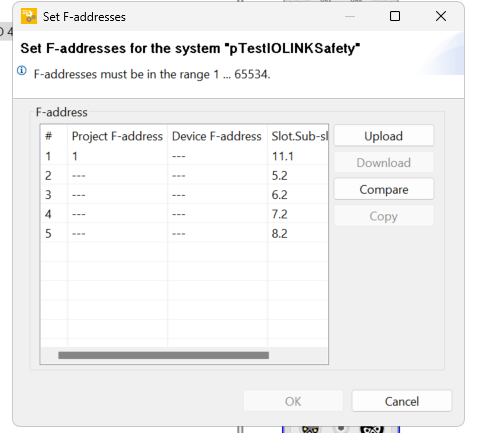
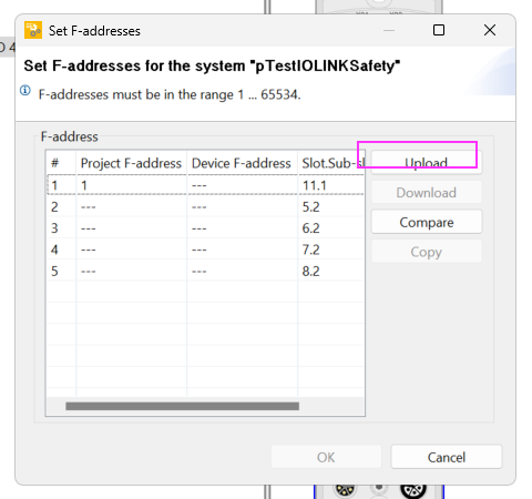
Upload
Click on the Uplaod button to get each Profisafe F-Address for PDP67 PN 8FDIO 4IOLS.
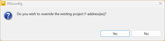
Proceed with Yes.
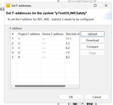
Done!
Compare
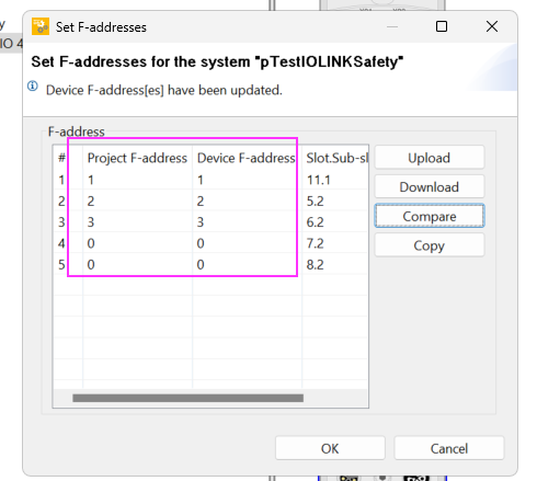
Next, click Compare to compare the F-Addresses of the project and the actual device.
Done! The project settings and the actual machine are the same.
How to refer this?
The F-Address setting here must match that of the Siemens TIA side. For example, if Slot.Sub-slot is 11.1, it corresponds to Sub Slot 11 on the TIA side.
Port 5 used this time corresponds to Sub Slot 5 2 on the TIA side.
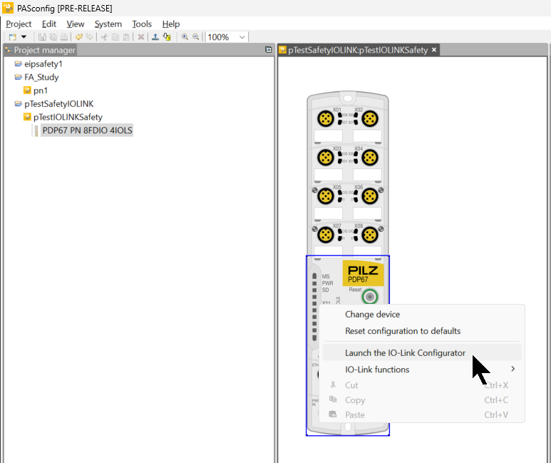
Configure IO Link
To configure the Safety IO Link settings for PDP67 PN 8FDIO 4IOLS, right-click on the module > Launch the IO-Link Configurator to launch the IO-Link configuration tool.
IO-Link Configurator has been started.
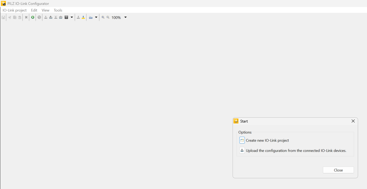
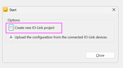
Click Create new IO-Link Project.
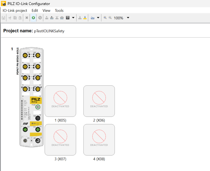
Done!A new IO-LINK Configuration project has been added.
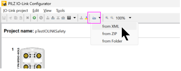
Install IODD File
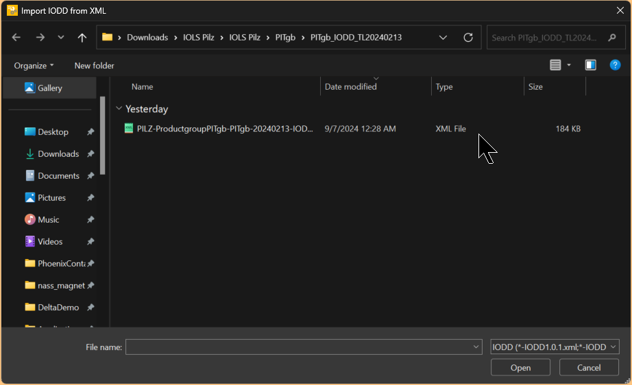
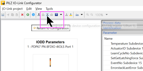
To install the IODD File, click the pink-bordered button and select From XML.
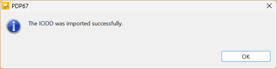
Select IODD File.
Done!
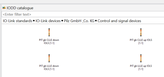
The IODD Catalog should show the device that was just installed.
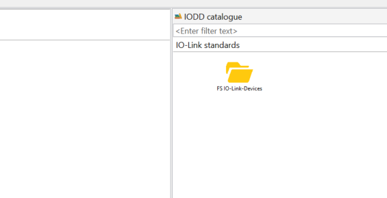
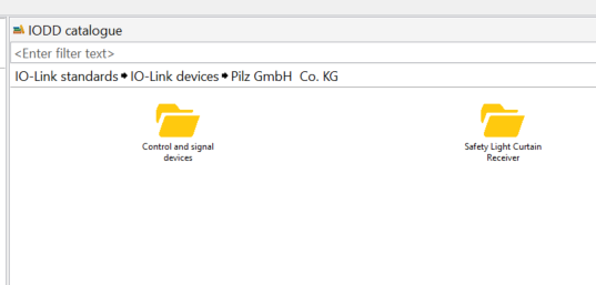
The one used in this article will also appear in the PITGB box.
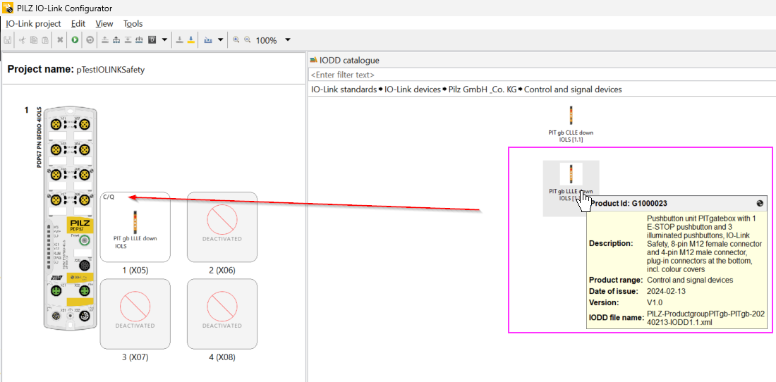
Insert IO-Link Device
Add a Safety IO-LINK device to be connected to Port5. Note that the Product ID must match the actual device.
IO-Link safety Device Mode..
IO-Link safety devices have the following operating modes:c
- Armed Mode
- Commissioning Mode
Armed Mode
This is the mode in which devices exchange data cyclically; a checksum is created based on a set parameter called TechParCRC.
This checksum must be the same on the device and in the IO-Link Safety master port configuration. Only then can data be exchanged safely.
In this mode, the device will not accept parameter changes. They must be set in commissioning mode.
Commissioning Mode
This mode is for safe parameter setting. To set Commissioning Mode, the device and port TechParCRC must be set to 0. Note that the device is shipped in Armed Mode.
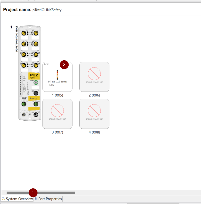
Port Configuration
Click Port Properties.
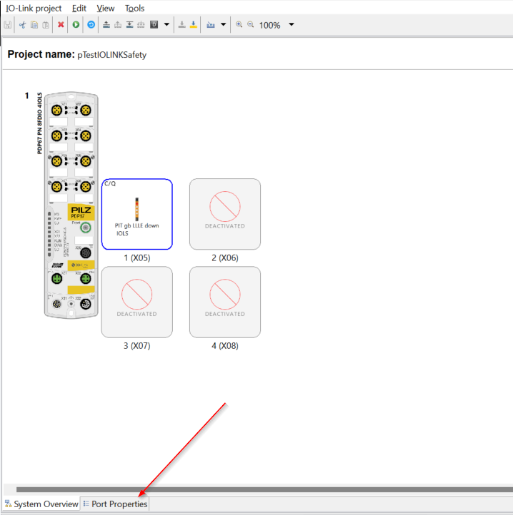
Configure the settings for each port on this screen.
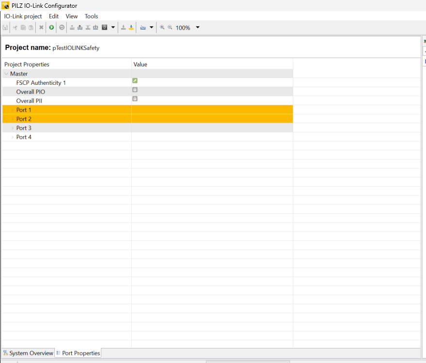
The parameters of each Port can be expanded as shown in the figure below.
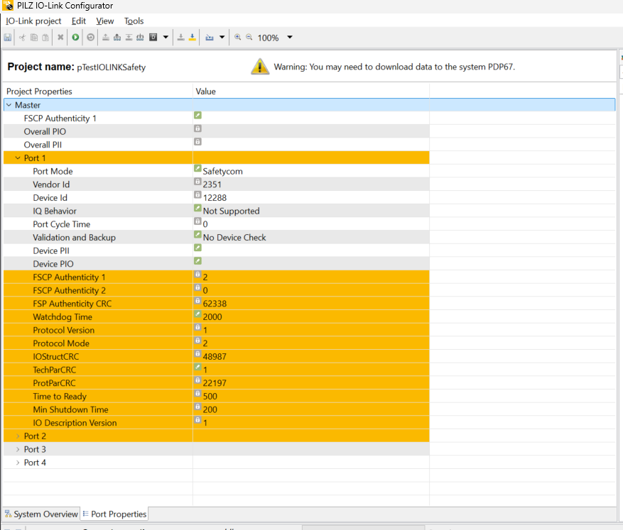
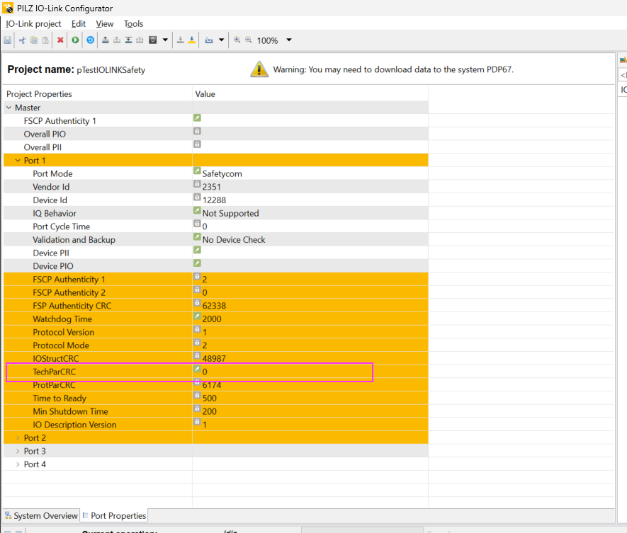
Set the TechParCRC here.

Set TechParCRC to 0 and switch the Safety IO-LINK device to Commissioning Mode.
Download
Download Port setting.
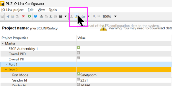
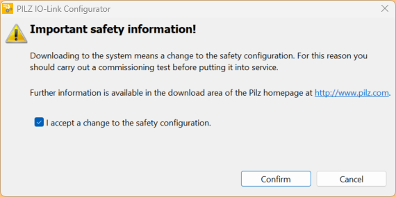
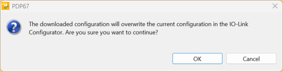
Proceed with Confrim to start Download.
Please wait a moment…

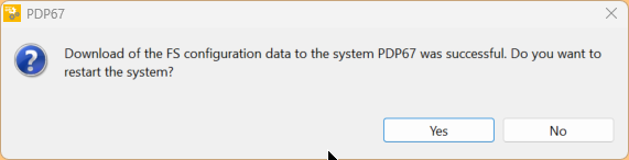
Click Yes to restart PDP67 PN 8FDIO 4IOLS.
Done!
Configure
Next, configure the Safety IO-LINK device by clicking on the System Overview>PIT gb box you just added.
The screen changes to the parameter screen of the PIT gb box.
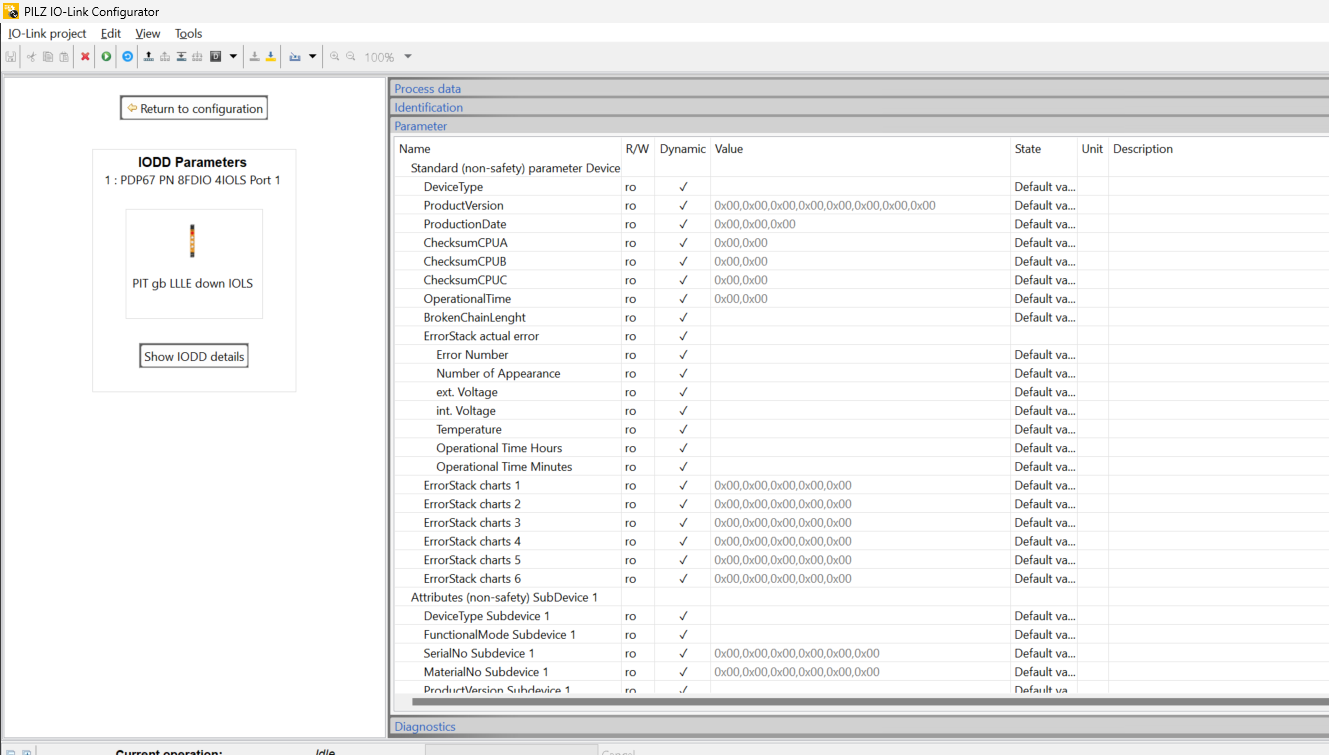
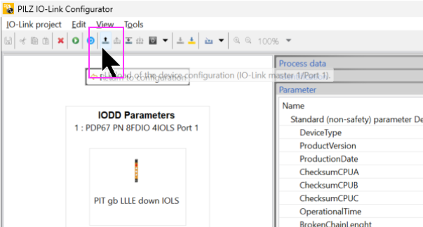
Uplaod
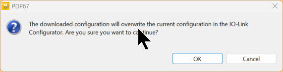
Upload the parameters of the Safety IO-LINK device.
OK to proceed.
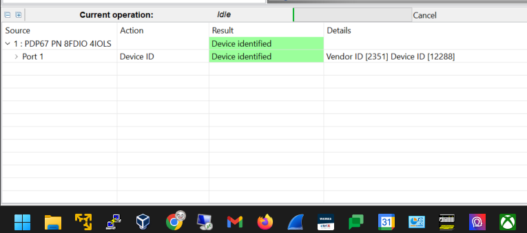
Done!The result is displayed as “Device identified” and the information is retrieved.
Change TestParCRC
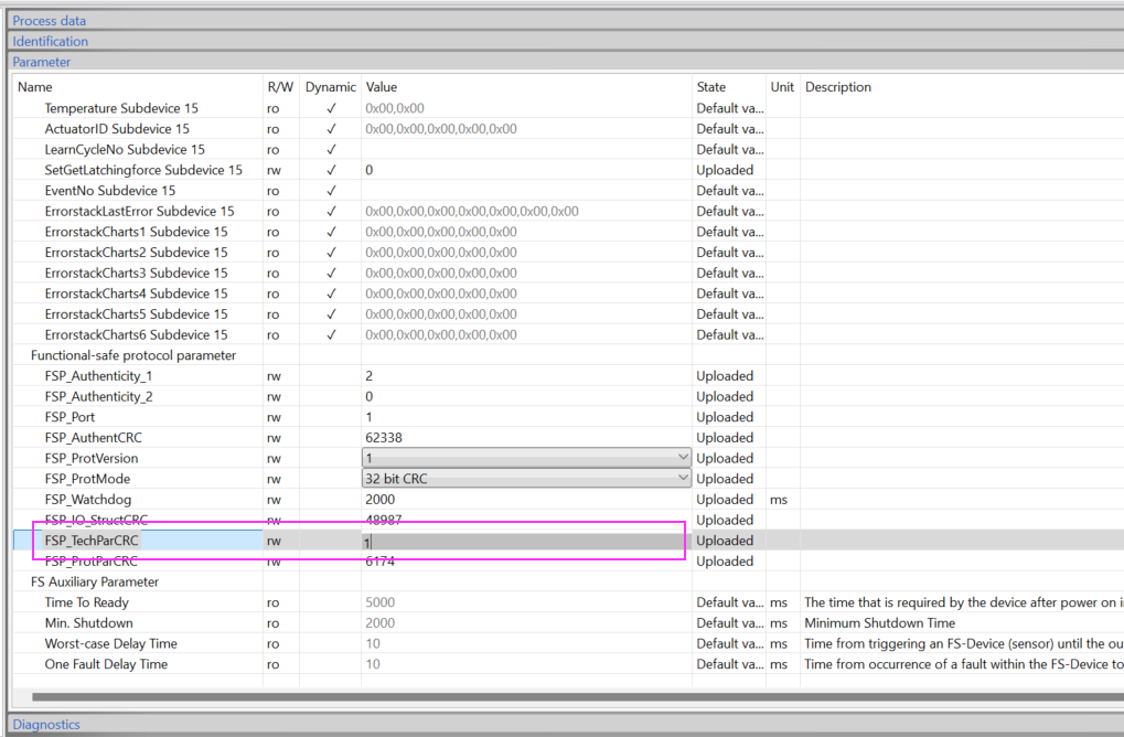
Open the Parameters Tab and look for the FSP_TechParCRC parameter.
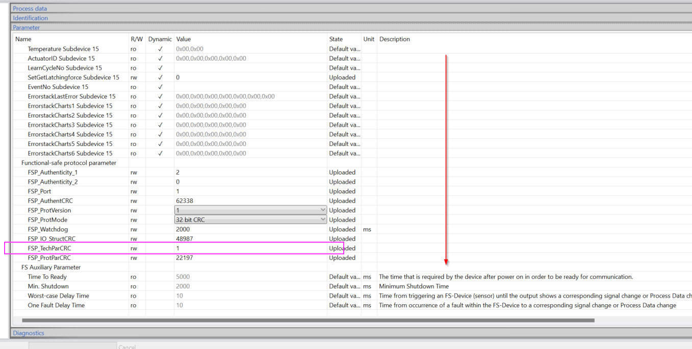
Set FSP_TechParCRC to 0 and change the Safety IO-LINK device to Commissioning Mode.
Download
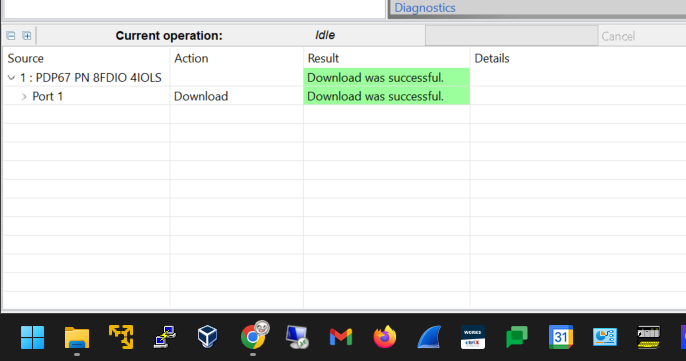
Since there are no parameters to change this time, download the Uploaded parameters to the Safety IO-LINK device as they are.
Done!The result is “Download was successful”.
Upload and check
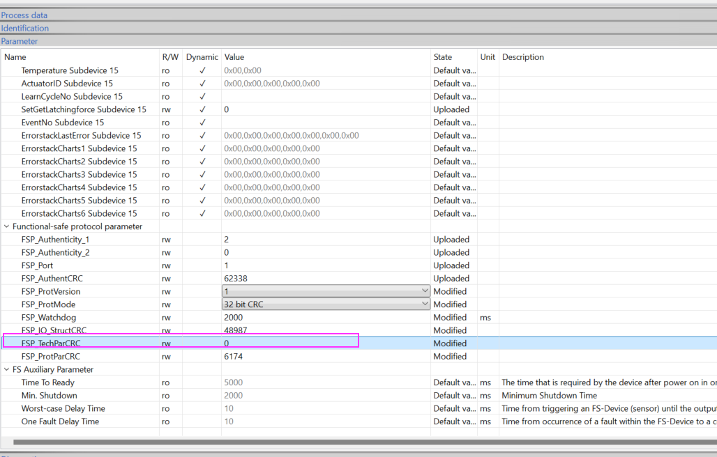
Now, let’s Upload the parameters one more time and check the TestParCRC value.
OK to proceed.
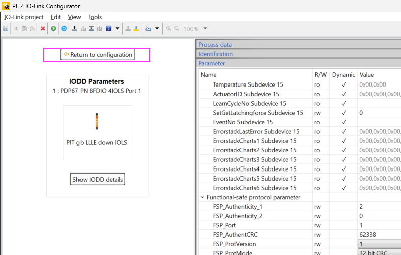
Open the Parameters Tab and see that FSP_TechParCRC is 0. Let’s change that parameter to 1 and change the Safety IO-LINK device to Arm mode.
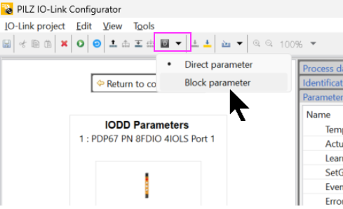
Block parameter Download
Download the Configuration and change the Block Parameter.
Finally, download your project to the Safety IO-LINK device.
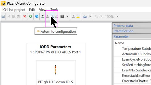
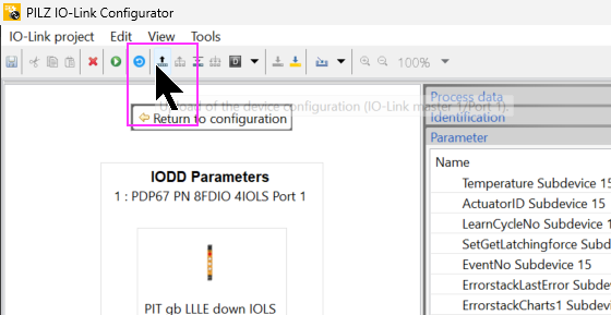
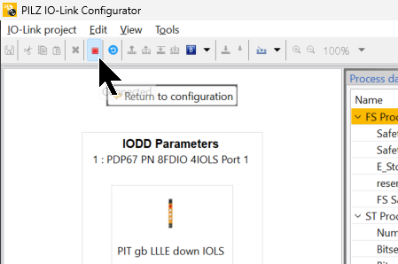
Click on “Return to Configuraton” to leave the parameter setting screen.
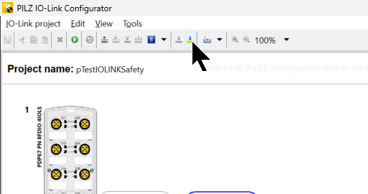
Download again
Finally, let’s download the project one more time to the module.
Monitor
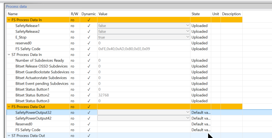
The IOLink Configuration Tool actually has a Monitor function, which can monitor the input/output data of Safety IO-LINK devices.
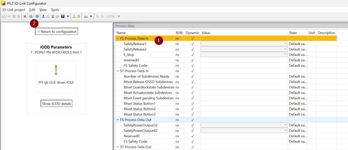
Result is displayed as “Port Connected”.
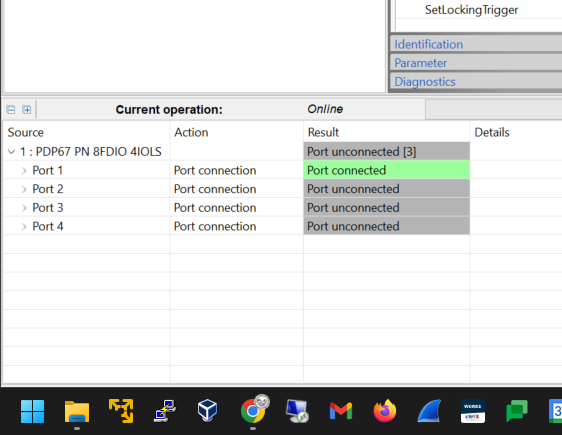
Safety The current value of the IO-LINK device can now be checked!
Finally, stop Monitor Mode.
Result
We were able to verify the communication status of PDP67 PN 8FDIO 4IOLS and S71516F from TIA.
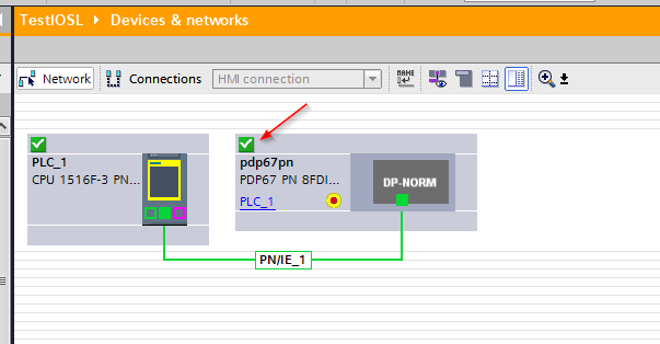
There is no QBAD signal from the safety program either.
You can see the actual operation in this video.
This video shows the LED status of the IOLINK Safety Port when it is communicating normally with an IOLINK Safety device.
This movie shows the LED status when communication is normal and the module is normal.
https://youtube.com/shorts/-xnDHG1UCUw
Download
You can download the article project at this Link.
https://github.com/soup01Threes/Siemens/blob/main/TestIOSL.zap18