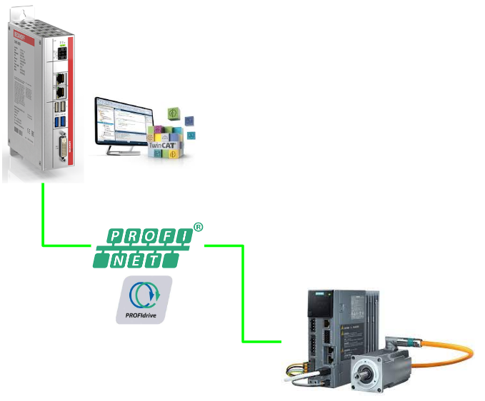
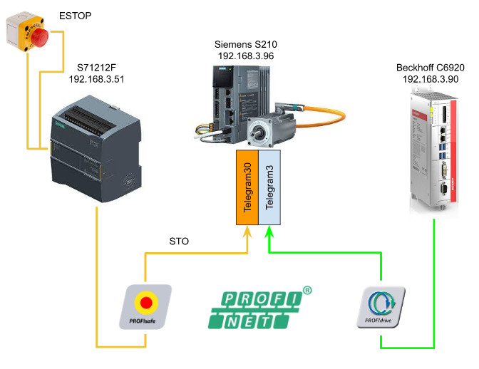
This is the second episode of running Beckhoff TwinCAT3 and Siemens SINAMICS S210 PN. Last time I controlled the S210 Drive from the TwinCAT3 Control panel, this time I want to incorporate Profisafe Telegram30, but Profisafe can not used in TwinCAT IPC.
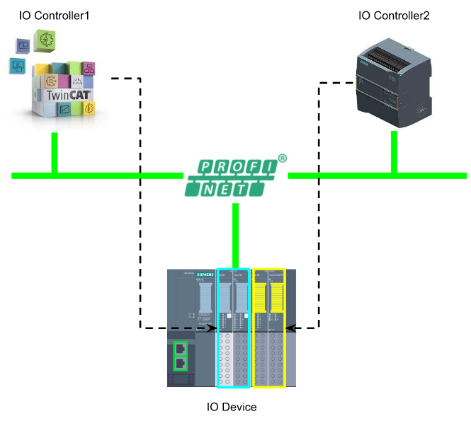
Here is my idea – I use Profinet’s Shared Devices function to control S71212F only Profisafe, the Main Motion Control is still by Beckhoff.
Thanks!
Because of Beckhoff Japan and mana Design works that lend the devices to me – I can create this post.
Beckhoff Japan
IPC6920-005 was lent by Beckhoff Japan, a Japanese subsidiary of Beckhoff. Founded in 1980, Beckhoff Automation is a German company at the forefront of the introduction of open automation systems based on PC-based control technology.
Beckhoff Japan Corporation Beckhoff Automation Co., Ltd. established its head office in Yokohama in 2011 and the Nagoya office in 2017.

Here is the Home page of Beckhoff Japan.
https://www.beckhoff.com/ja-jp/
Mana Design Works
Siemens SINAMICS S210 was lent by Mana Design Works.
Mana Design Works is an official solution partner of Siemens ,headquartered in Osaka, and always make optimal proposals with Siemens CPUs, HMIs, Drives, Motion Controllers, and SCADA.

Here is the homepage of Mana Design works.
Reference Link
English Version
Japanese Version
Video
English Version
Part2
Part1
Japanese Version
Part2
Part1
Siemens- Safety Program
We will use Siemens Engineering Tools – TIA to create some sample Safety Program.
Only LAD and FBD can be used in the safety block, and the error detection,error process and safety test are provided automatically in these safety blocks.
LAD/FBD
For Siemens ‘ PLC, 5 types of Program languages(SCL/STL/LAD/FBD/S7 Graph) can be used in the standard program, but only LAD/FBD can be chosen in the Safety Block with Limit Functions.
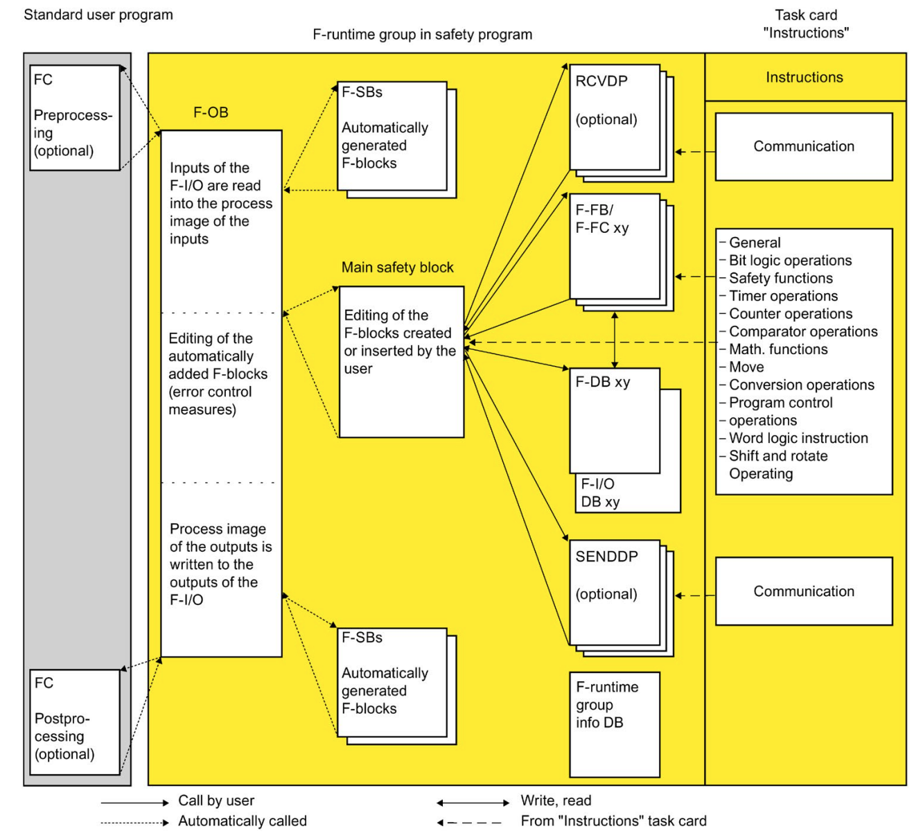
Safety Program Structure
Max 2 F-Runtime groups can be configured in your Siemens PLC and each F-runtime group has their own Blocks (from your Safety Applications) / F-Blocks (Automatically Created)/F-runtime DB and F-I/O DBs.
Here is the structure of the Siemens Safety program.
Support Data Type
These Data Types are supported in the Safety Program.
- BOOL
- INT
- WORD
- DINT
- DWORD(S7-300/S7-400)
- TIME
- ARRAY[*]
- UDTはNG
- BoolはNG
- WordはNG
- TimeはNG
- F-Compliant PLC data type
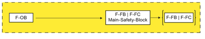
Main safety block
The Main Safety block is the first program block called in your program.
In S7-1200/1500 FCPU, this Main Safety Block is called by F-OB and F-Runtime Group is assigned.
F-Runtime groups
Inside the Safety Program , we can have max 2 F-runtime groups and Inside the F-runtime groups, you can find so many components that are linked with F-blocks. For Example,
- Main Safety Block that called from F-OB.
- Main Safety Block(F-FB/F-FC that linked with F-OB)
- F-FBs or F-FCs that were created from other Safety-FBDor Safety LAD.
- F-DBs
- The F-DB that with F-Runtime group information
- F-I/O DB
- F-Blocks are Automatically created.
- etc..
ESTOP Function
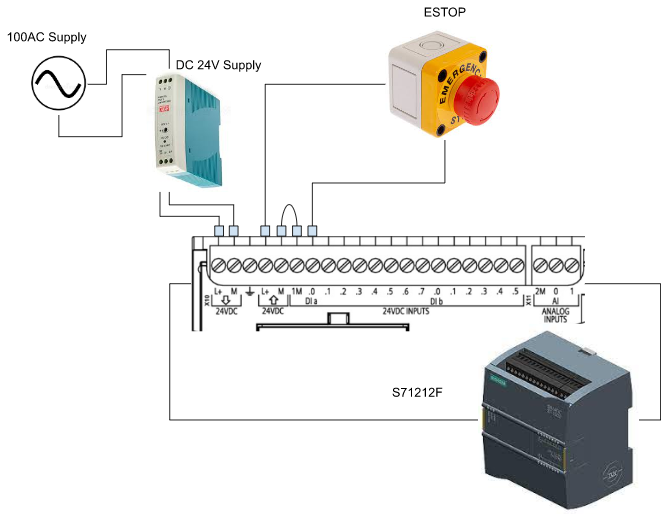
Let’s Try the Safety features first. We have an ESTOP that is connected with S71200,in the input terminal I0.0.
Wiring
For the Sink Input, please connect “-” and “M” together.
Function Block
This is the Safety Function Block for ESTOP applications – A Standard Function Block from Siemens.By using this Function Block, we did not need to implement the ESTOP program and full-fill in Stop Category 0 and 1.
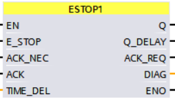
VAR_INPUT
| E_STOP | BOOL | The ESTOP Signal |
| ACK_NEC | BOOL | 1=Reset is nesscary |
| ACK | BOOL | 1=Reset |
| TIME_DEL | TIME | Time Delay |
VAR_OUT
| Q | BOOL | The status of ESTOP、1=OK |
| Q_DELAY | BOOL | The status of ESTOP、1=OK+Delay Time |
| ACK_REQ | BOOL | 1=Requesting the Reset signal |
| DIAG | BYTE | Diagnostic Information |
Implementation
Create new Project
Start the TIA>Project>New.

Enter your project name>Create.
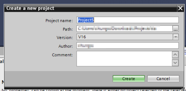
Project is created.
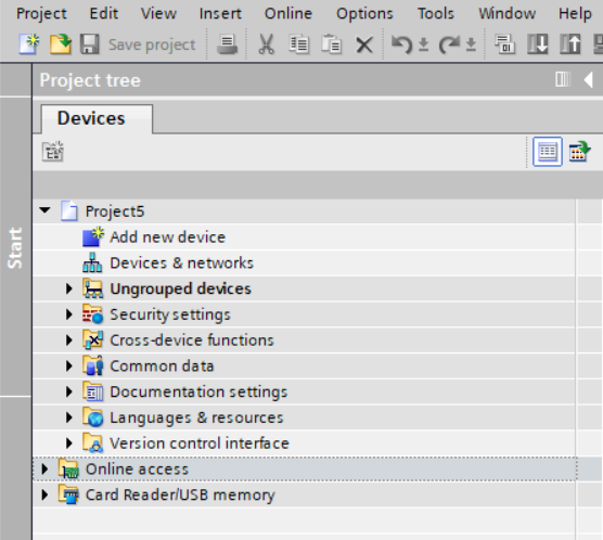
Add S71200
Insert S71212F in our project. Click the “Add new device” Button.

Choose CPU1212FC and your firmware version>OK.
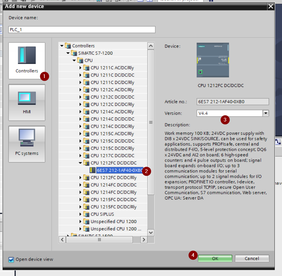
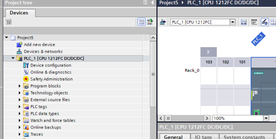
S71212F is inserted.
Configure the IP
Click PLC_1>Device Configuration.

Choose Properties>PROFINET Interface[X1]>Ethernet address,
select “Set IP address in the project” and enter 192.166.3.51.

Configure the Start-up Cycle Time
Change the Startup Cycle time in the startup, because the initial value is 60s.

Add Tags
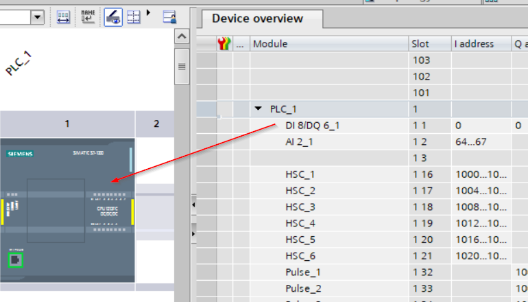
we can set Tag to ESTOP. It is connected to I0 of the S71212F and the I address is initially set to 0 in the DI8/DQ6_1 column.
In other words, you can think like I0=I0.0 and I1=I0.1. ESTOP is wired to I0, so the CPU address is I0.0
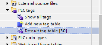
Open PLC tags>Default tag table.
NameをiESTOPに設定し、Data typeはBool、Addressを%I0.0に設定すればOKです。

PROGRAM
Now we can create some Safety Programs.
Add ESTOP1 Data Type
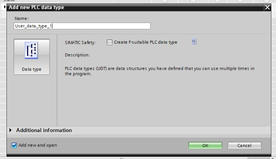
Go to PLC data types>Add new data type to create a safety data type for ESTOP1.
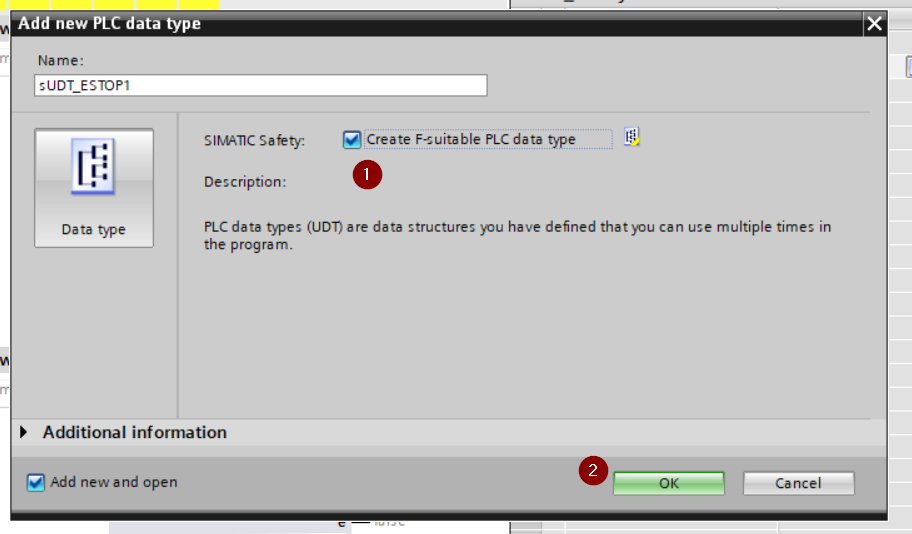
Enter the PLC data Type name>check the “Create F-Suitable PLC data type” checkbox>Ok.
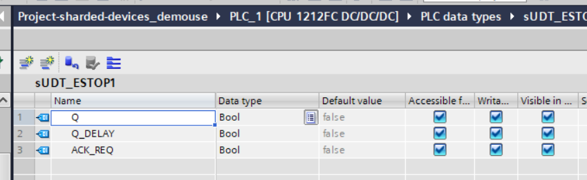
Q,Q_DELAY and ACK_ACK_REQ are defined.
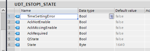
Add Normal Data Type
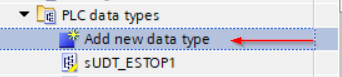
Go to PLC data types>Add new data type.
Enter the user data type name>OK.
define the ESTOP state and the status that are dependent on that State.
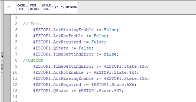
Add Function
Go to Program blocks>Add new block.
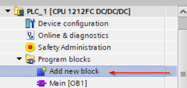
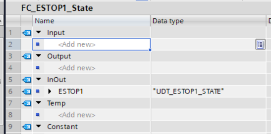
Enter the Block name>Select Function and SCL as the implement language>OK.

InOut parameter with Data type “UDT_ESTOP_STATE ” is defined in the Function.
Program will reset all the output and output the status bit that depends on the state byte.
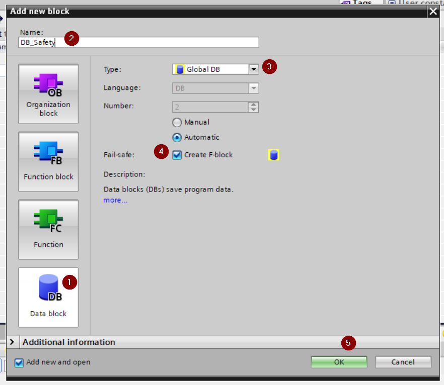
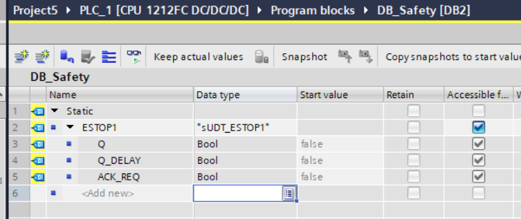
Add Safety DB
Now we will create the Safety Data Block.Go to Program blocks>Add new block.

Select Data block>Enter your Safety DB name>choose Global DB as the Type> Check the “Create F-Block” check box and OK.
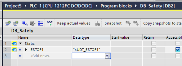
Safety DB is created.
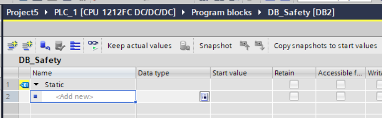
define a variable with Safety User data type “sUDT_STOP1” in your safety Data block.
Add Non-Safety DB
Then we can create the Non-safety DB. Go to Program blocks>add new Block.

Enter your Data Block name>select Data Block>choose Global DB as the Type and OK.
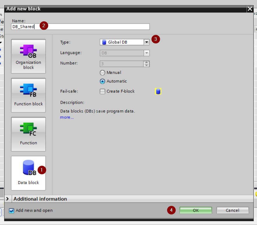
DB is created.
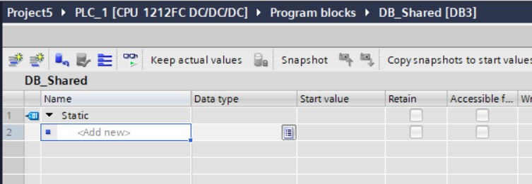
All variables that we need are pre-defined inside DUT_ESTOP1_STATE.

Add ESTOP1
Now is the Time to create the Safety Program!Click the Main_Safety_RTG1.

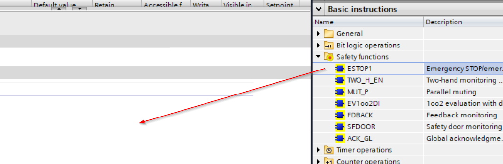
All the blocks with yellow color are indicated as “Safety”.
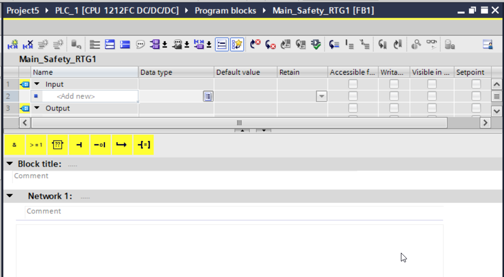
Open Basic instructions>Safety functions and Drop “ESTOP1” into Network1.
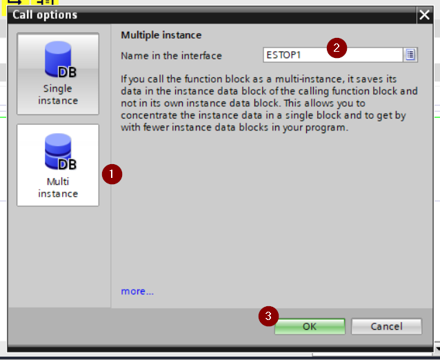
Call options are shown – Choose “Multi Instance”>Enter your Instance name>OK.
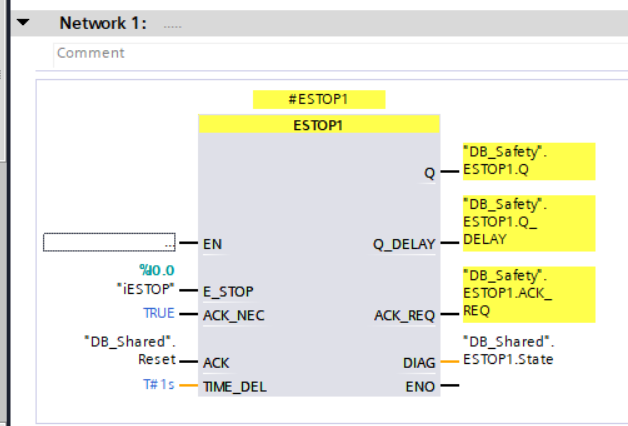
Safety Function Block is inserted in your safety program.

For the E_STOP signal, Link the I0.0 Tags that you defined in the previous step.
ACK_NEC=it means that the reset operation is necessary, and assign the ACK signal with the variables that you defined in the Global DB.
Add Program in OB1
Finally we can open OB1 and call the Function to get the ESTOP1 current status.

Call the FC1 in the OB1 and assign all the parameters – Done!

Trace
There is a Trace function in Siemens TIA Tools for your to Monitor all the variables.
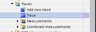
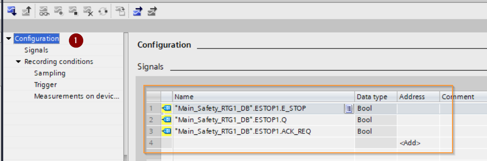
Go to Traces>Trace.
Open the Configuration, And enter all the variable names that you defined in the Main_Safety_RTG1_DB and used as ESTOP1 Function Block.
Go to Recording conditions>Select Sample with FOB_RTG1.

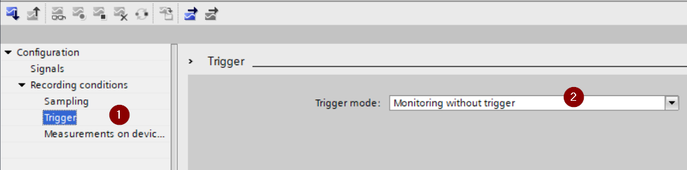
Go to Trigger>Trigger Mode and select Monitoring without trigger.
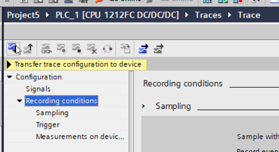
Press the Transfer trace configuration to device to download your Trace configuration.
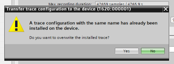
A warning is shown if there is a Trace configuration with the same name.Press Yes to download the configuration.
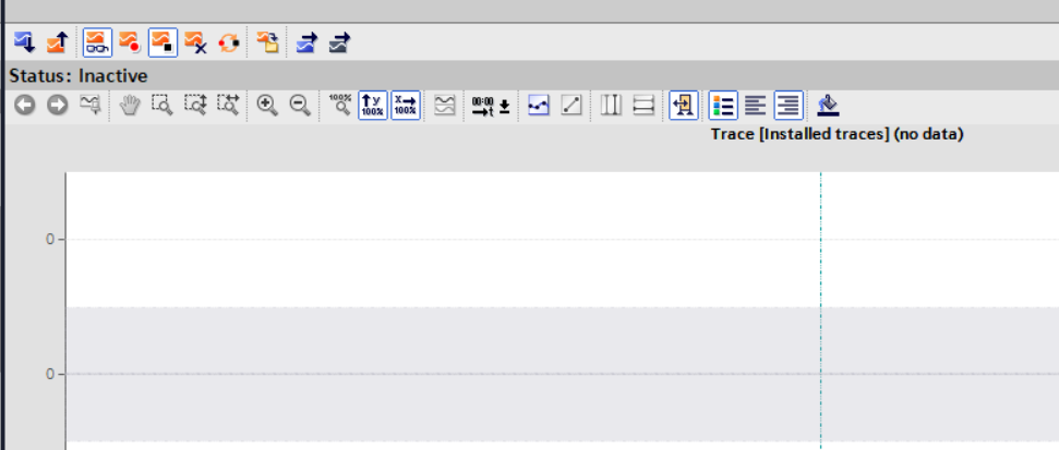
The Trace screen is displayed.
Click “Activate recording” to take the data.

The actual value is taken from the CPU and recorded inside the CPU.
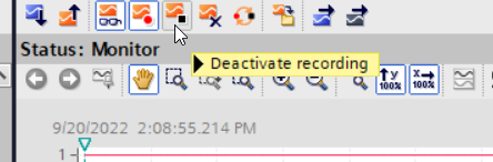
We can stop the recording by clicking the “Deactivate recording” button.
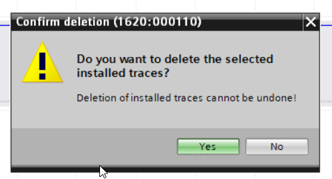
Click the “Delete Trace from device” button if you want to delete the trace.

Yes.
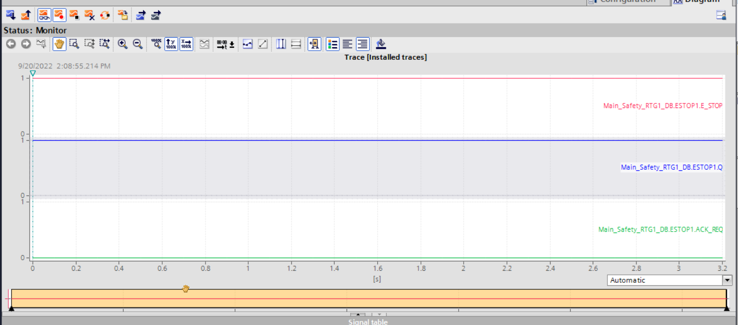
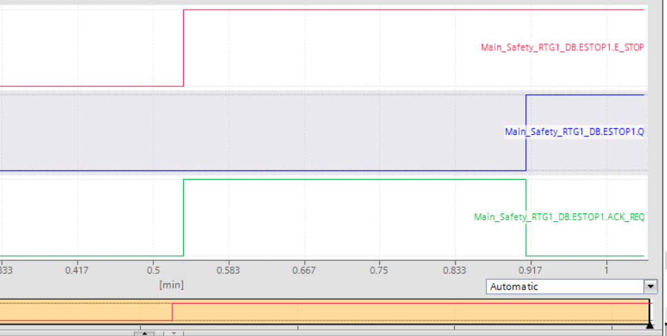
Result
The ESTOP Signal(Red) is OFF and Q Signal(Blue) is also in “OFF” condition.
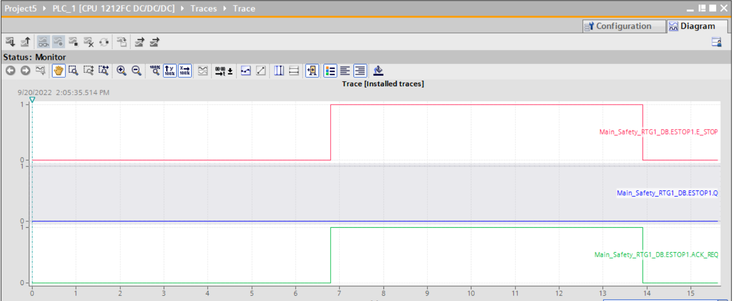
Then we can Change the ESTOP signal to True(Red) and the Q Signal(Blue) is still in OFF, but ACK_REQ(Green) is changed to True – An Acknowledge signal is needed.
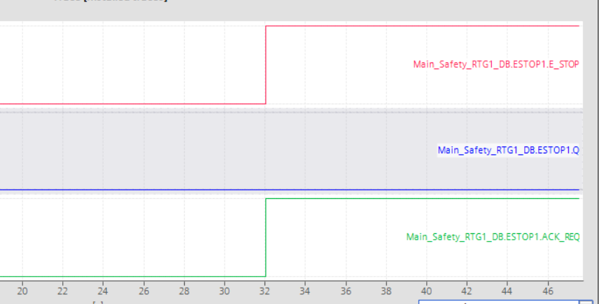
The Q Signal(Blue) becomes true when an Ack signal is input.
Shared Devics?
PROFINET has some optional features (although some PN devices may not be available), such as Shared input, Shared Device and Fast Start Up (FSU). This time we will introduce the Shared Device.
To put it simply, Shared Device allows SubSlots in one Station to be accessed from multiple Controllers. A common application is that a Safety Controller that supports PROFI-safe in the same Station ,accesses only the SubSlot of SafetyIO and implements a Safety Function (eg STO). Other Standard Subslots are accessed by the Standard Controller to control the equipment.
Advantages
There are the following advantages while Using Shared Device,
- lessIO Devices and modules – reduce equipment costs.
- IO Data can be accessed in real time from multiple CPUs
- Saves space inside the panel
- Data can be exchanged without implementing CPU-CPU communication
- no need to create CPU-CPU communication programs
Requirement
- Step7 TIA >V12 SP
- Siemens CPU Firmware >V1.1
- IO Devices that support the Shared Devices feature
And also the project must be separated if a Shared device is used.

If iDevice and Shared Device are both used..
If IDeives and Shared Devices are both used in your application..
- S7-1500 with firmware > V1.5, and export the GSDML file from TIA and import it to your IO Controller project.
- If S7-300,S7400 is used, export the GSDML file from Step7 V5.x and import it to your IO Controller project.
- ET200SP-CPU with firmware > 1.6, and export the GSDML file from TIA and import it to your IO Controller project.
Rules
- The hardware configuration of those devices must be the same in both projects.
- IP、DeviceName must be 100% the same in both projects.
- The Send Clock setting must be 100% the same in both projects.
Safety
Compared to standard Drive functions, Safety Integrated Functions have an even lower error rate.Its Error Rate is related to Performance Level (PL) and Safety Integrity Level (SIL).
And the Safety function allows User to reduce the risk of application.
Safety Integrated (“Drive-Integrated”) in the Siemens S210 Drive means that the safety function is Built inside the Drive, no external component expansion is required.
Safety Integrated Functions
- Safety Integrity Level(SIL) 2, DIN EN61508
- Category 3, DIN EN ISO 13849-1
- Performance Level(PL) d, DIN EN ISO 13849-1
Response Times
Safety Integrated Function is executed in Safety Monitoring cycle 4ms.
The evaluation time of the PROFISafe Telegram used this time is roughly twice the Monitoring Cycle.
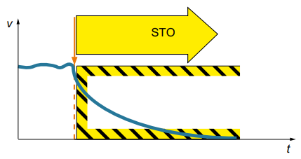
STO(Safe Torque Off)?
STO ensures that when triggered as a Safety function with Safety Torque OFF, it will not power the motor any further with Torque OFF immediately. Its safety functions correspond to Catalog 0 of EN 6024-1.
If the STO is triggered while the motor is running, it will stop the motor.
The Siemens S210 can be used via Failsafe Digital Input or PROFIsafe.
Telegram30
By using Telegram30 in Drive, you can perform PROFIsafe communication with F Host (IO Controller that supports PROFIsafe). This time I will introduce Telegram30, and there are other PROFIsafe Telegrams such as Telegram900.
Telegram30 occupies 6Bytes of IN/OUT data. The 0th and 1st bytes are safety user data, and the remaining 4 bytes are used for PROFIsafe communication.
Control word S_STW1
Here is the STW1 Structure of Safety Telegram 30.

Stauts word S_ZSW1
Here is the ZSW1 Structure of Safety Telegram 30.

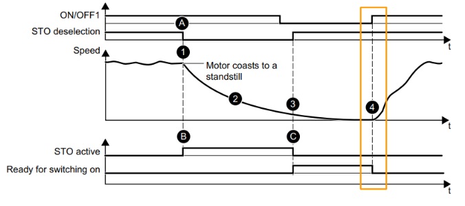
Flow
STO was triggered from PROFIsafe or Failsafe Digital Input when the motor was initially running. At that time, the input of Telegram30 is fed back with the STO_active signal.
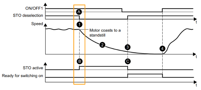
Drive immediately activates the Safety function and ensures that no more power is applied to the motor while the motor is torque OFF. Then coast to stop the motor.
Of course the STO function completely blocks the restart of the motor.
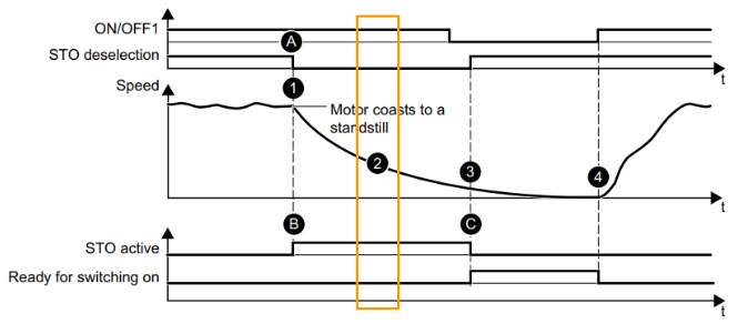
When the Drive disables the STO signal again, the Drive can return to the “Ready” state. with the following options
- Reset from IO Controller
- The Reset button from the Drive
- resume the power
- Reset from web server in S210
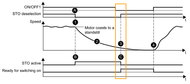
Finally, using the ON/OFF1 pulse signal to restart the Drive.
Implementation
Siemens S210 Side
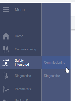
Enable the Siemens S210 Profisafe function from the Web server.
Go to Safety integrated and click the Commissioning.
Enter your Safety integrated Password>Enter.

A password accepted is shown.

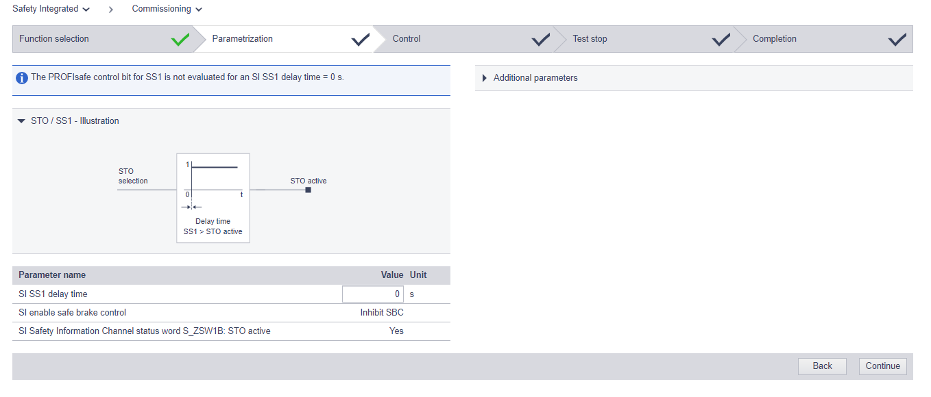
Now we can configure the Profisafe setting.
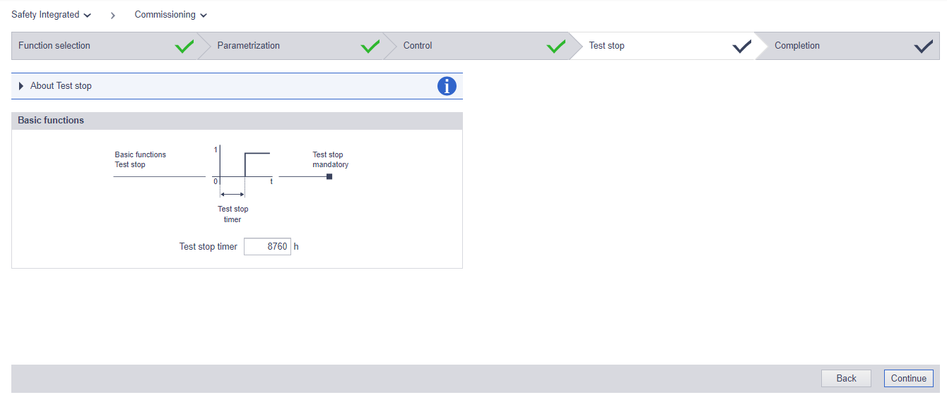
Choose Basic Function in the Safety Integration options > PROFIsafe in the Control via selection and press start to continue.

We will use the default setting here. Press Contiune.
Select Telegram 30 in the PROFIsafe Telegram Type, and set the PROFIsafe address as “1”, choose STO and Continue.

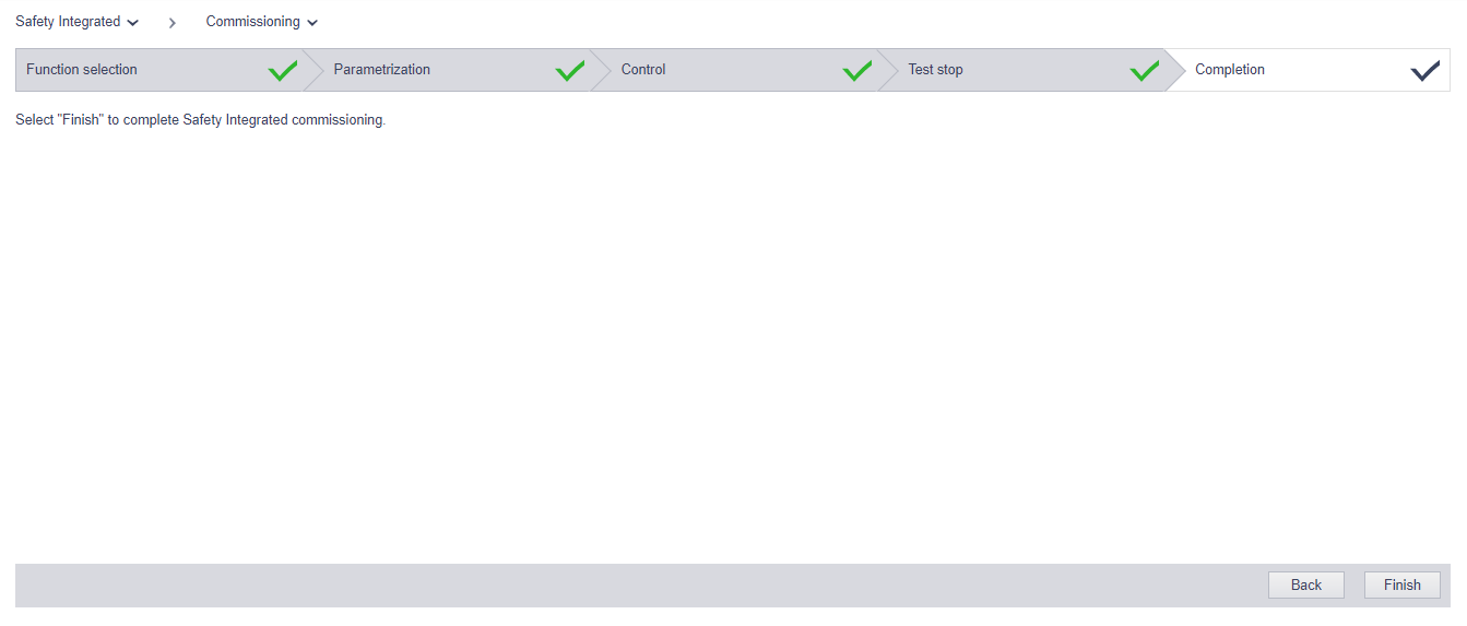
Continue with the Default setting.
Finish!
Save all parameters(Power failure-proof) and Finish.
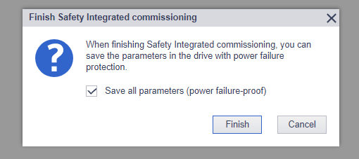
Please wait a minute..

Preaction
Donwload Library
Download the library for safety from this link:

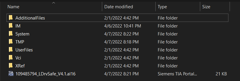
A Zip file is downloaded.
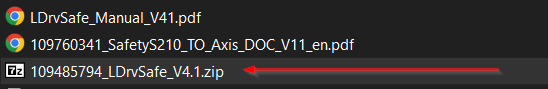
Please unzip it and we will import this library into TIA.
Import Library
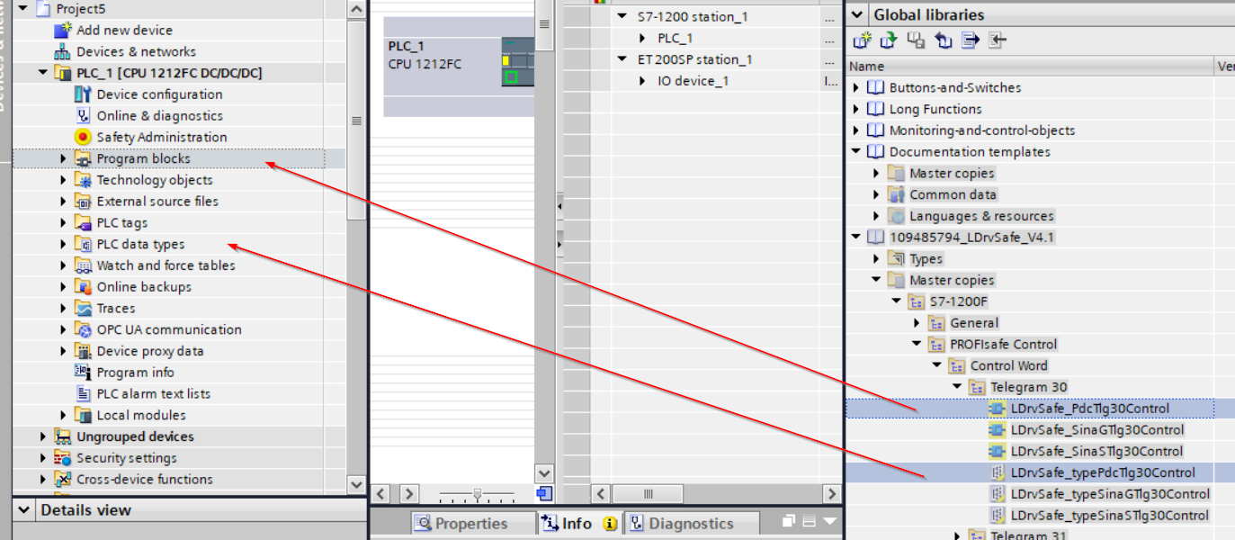
Start up your TIA and Click the “Open library” button of Global libraries on the right side.

Choose the library file with .al16 >open.

The library is imported in your TIA tools.

Control Word
Expand S7-1200F>PROFIsafe>Control Word>Telegram 30 and Drop LDrvSafe_PdcTlg30Control and LDrvSafe_typePdcTlg30Control inside your Project.
Status Word
Expand S7-1200F>PROFIsafe>Status Word>Telegram 30 and Drop LDrvSafe_PdcTlg30Status and LDrvSafe_PdcTlg30Status inside your Project.

LDrvSafe_PdcTlg30Control
We can use this Function Block to control Telegram30 of SIMATIC Micro System .

VAR_INPUT
| Parameter | Data Type | Description |
| STO | BOOL | Safety Torque Off(STO)Safety1=Deselect、0=Select |
| SS1 | BOOL | Safety STOP1(SS1)Safety1=Deselect、0=Select |
| SLS | BOOL | Safety Limit Speed(SLS)1=Deselect、0=Select |
| SLT | BOOL | Safety Limited Torque(SLT)1=Deselect、0=Select |
| ackSafetyFaults | BOOL | Fail-safe acknowledgment, ack by a rise up edge |
VAR_OUTPUT
| Parameter | Data Type | Description |
| PdcTlg30Control | LDrvSafe_typePdcTlg30Control | The output of Telegram30 |
LDrvSafe_PdcTlg30Status
We can use this Function Block to receive and define the signals of Telegram30 ,in a SIMATIC Micro System .

VAR_INPUT
| Parameter | Data Type | Description |
| PdcTlg30Statusl | LDrvSafe_typePdcTlg30Status | The input of Telegram30 |
VAR_OUT
| Parameter | Data Type | Description |
| safetyFaultActive | BOOL | Fail-safe is Activated |
| STOactive | BOOL | Safety Torque Off(STO)1=Active |
| SS1active | BOOL | Safety STOP1(SS1)1=Active |
| SLSactive | BOOL | Safety Limit Speed(SLS)1=Active |
| SLTactive | BOOL | Safety Limited Torque(SLT)1=Active |
Install GSDML File
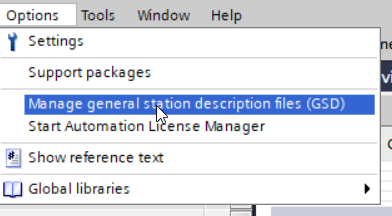
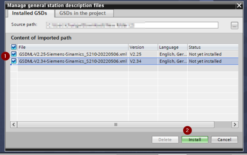
Go to Options>Manage general station description files(GSD) to import the GSDML file from TIA.
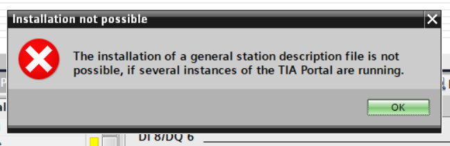
Please close all other TIA instances or restart the PC , if the following error is shown.
TIA will scan the source path that and find out the GSDML files.

Select all>Install.
Please wait a minute..
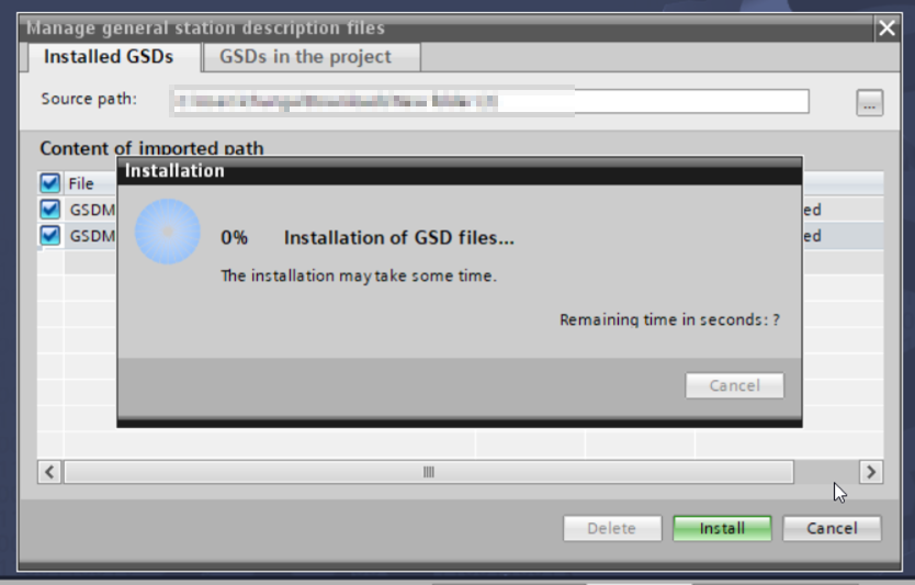
Done!

TIA will automatically update the catalogs..

Hardware Configuration
Add S210
Insert S210 in your profinet configuration first.Open the Product Catalog in the right side and select SINAMICS S210 PN V5.1>Drop inside your network.

SINAMICS S210 PN V5.1 is inserted.

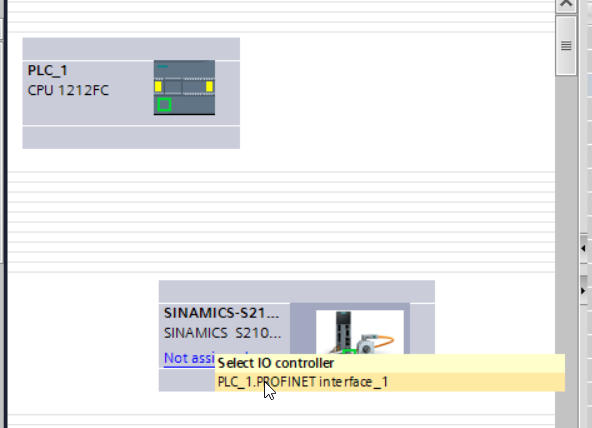
Click the “No assigned”> select >PLC_1.PROFINET interfaac_1.
PLC_1.PROFINET interfaac_1 = S7-1200 Profinet Port.
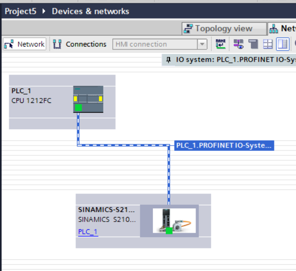
S210 and S7121F are configured with a profinet connection inside the project now.
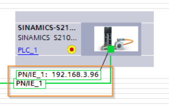
Set IP Address
Select the “Eye Icon Show address labels ” from TIA.

The ip address of SINAMICS S210 PN V5.1 is displayed. We can directly change the IP address in the PN/IE_1 field.Please make sure the IP address is the same as the IP address that you configure on the TwinCAT side.
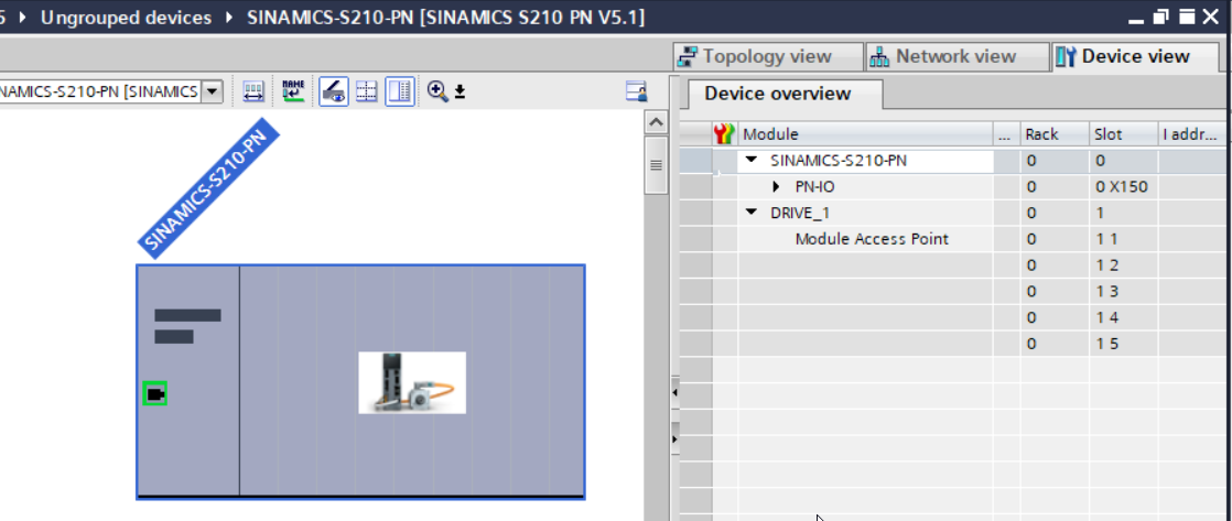
Add Telegram
By inserting the communication telegram, Double Click the S210 ICON.

Device View is shown.
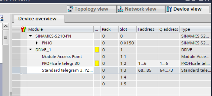
Insert PROFISafe Telegram30 and Standard telegram3 from the Catalog.
The configuration must be 100% the same as the TwinCAT3 side.
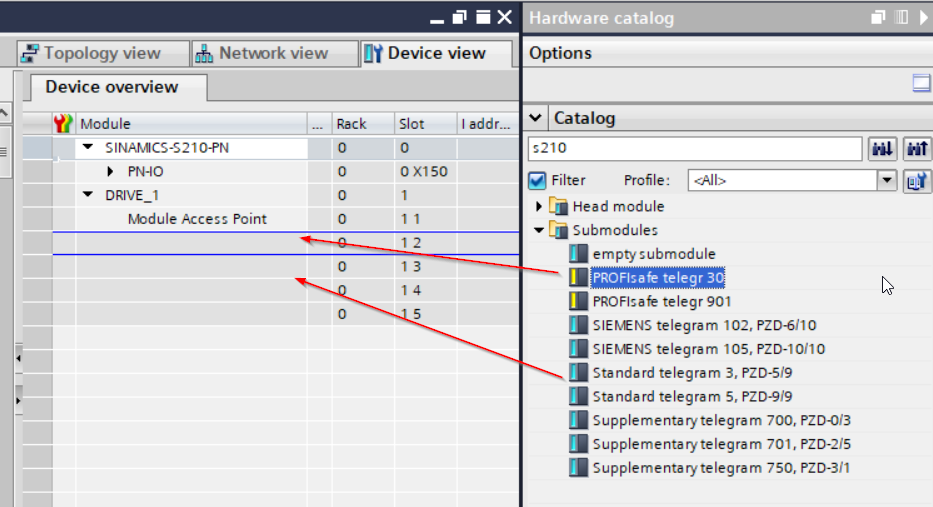
Just like this!
Telegram3 and Telegram 30 are inserted in your SINAMICS S210 PN V5.1 now!
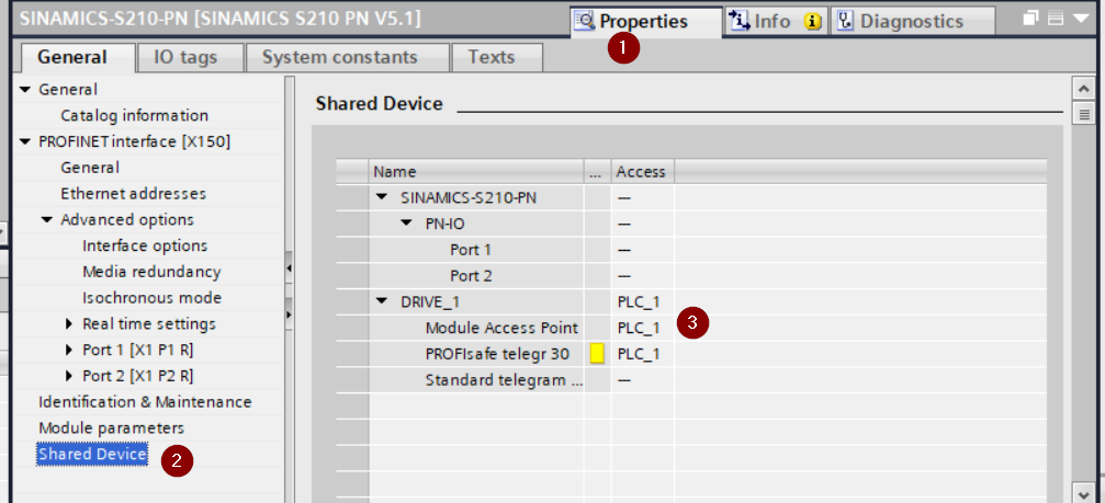
Set Shared Devices
Finally we need to configure the Shared Devices.Go to Properties>Shared Devices and Set the Access properties of Drive_1,Module Access Point and PROFIsafe as True.
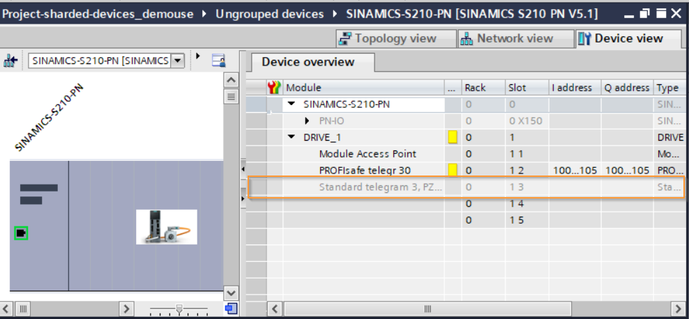
Device ViewからSINAMICS S210 PN V5.1を見るとTelegram3が灰色になり、I addressとQ addressにも設定できなくなります。それはSINAMICS S210 PN V5.1いまのTelegram3 SlotがS71212Fからアクセスしないようになっています。
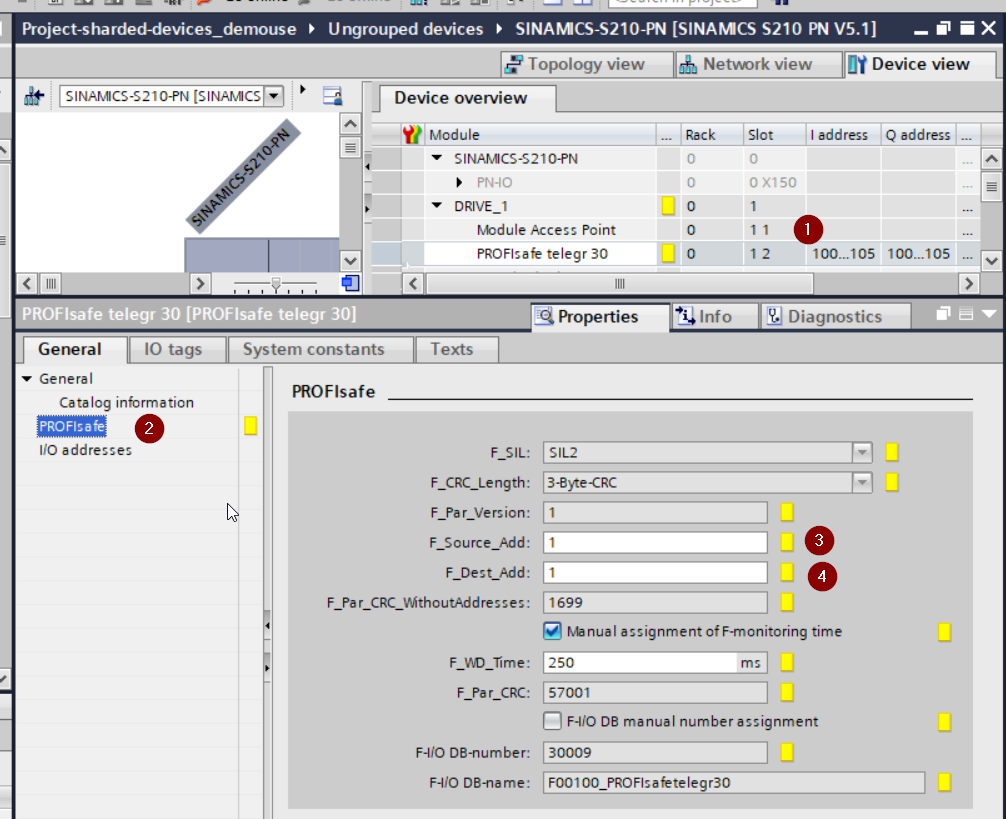
F-Address
PROFIsafe Telegram30をクリックし>PROFIsafeを開いて、F_Source_Addは1のままでOKで、F_Dest_Addは先程S210 Web serverからセットアップしたF_Dest_Addに合わせてください。
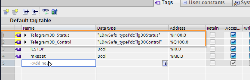
Define Tags
PROFINsafeのIO Tagsを定義します。
PLC tags>Default tag tableを開きます。

変数名はわかりやすく定義し、Data TypeをライブラリからImportしたLDrvSafe_PdcTlg30ControlとLDrvSafe_PdcTlg30Statusを設定し、AddressはDevice Viewの先頭に合わせましょう。
Program
Time to Create the Siemens Safety Program!
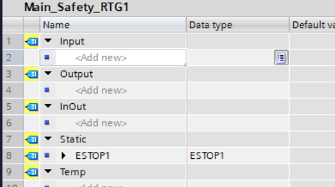
Safety Main_Safety_RTG1
VAR
define the Function block instance in the Static field.
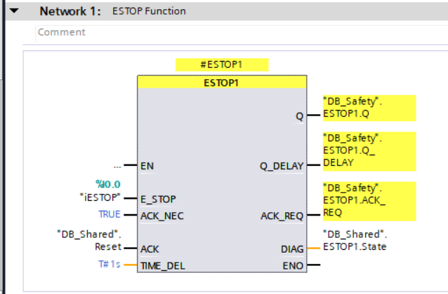
NTW1
Call the ESTOP1 function block and assign all the signals.
NTW2
Call the library that we imported in the previous step to get the current status of Telegram30.

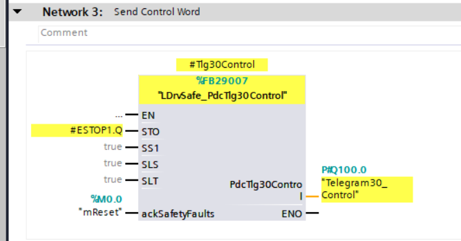
NTW3
Call the other library from Siemens to control the telgram30.
For the STO Signal, the output of the function block ESTOP1.Q is assigned.
Download the project to your CPU.
TwinCAT Side
In TwinCAT Side, we only need to configure the Shard devices.
Add Telegram30
Right Click the SINAMICS S210 PN V5.1>Term 2(DRIVE) that you inserted in the previous step.
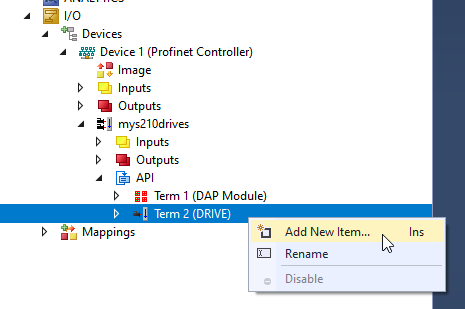
Insert Telegram30 in the submodule.
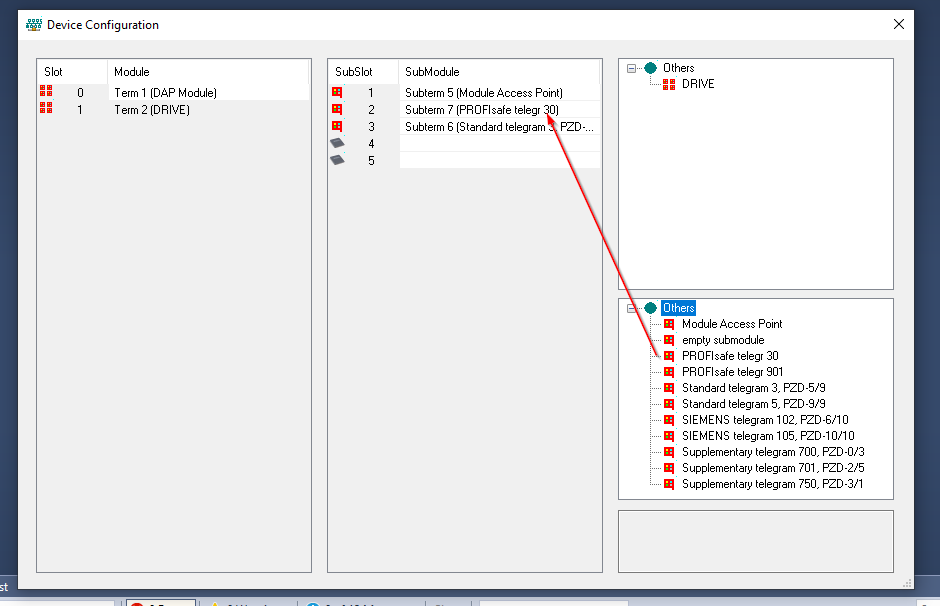
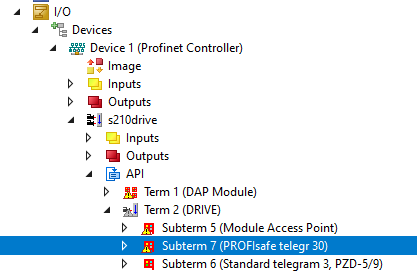
PROFIsafe Telegram30 is inserted.
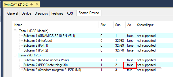
Set Shared Devices
Now we can configure the Shared Devices – Click the SINAMICS S210 PN V5.1.
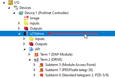
For Telegram3
Only Telegram3 is controlled by TwinCAT and changes the Access to True, then all other items to fault.
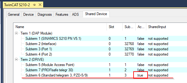
For Telegram30
Sure, Telegram30 access is False.