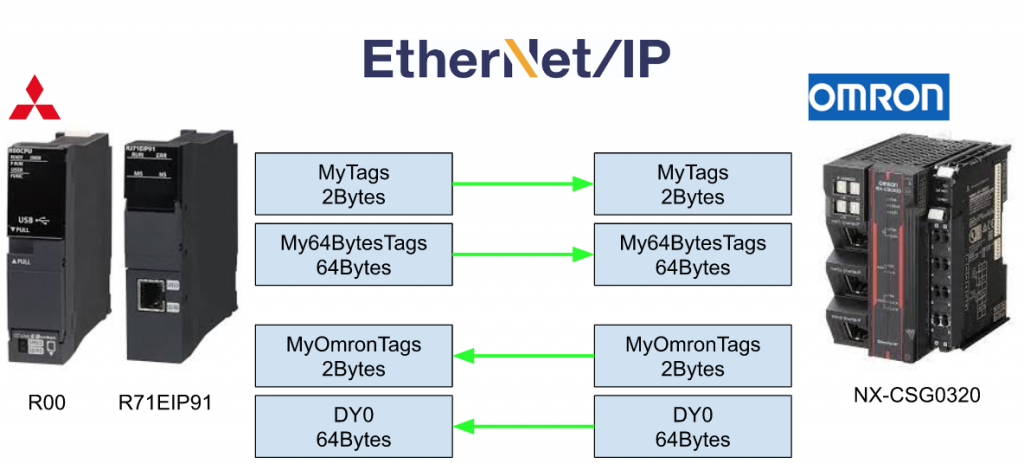
Here is a tutorial to show you how to configure the Mitsubishi RJ71EIP91 modules and OMRON NX-CSG320 with Class Tag Communication.
Let’s start!
Configuration
Reference Link
http://soup01.com/en/category/protocol-en/ethernet-ip-en/
http://soup01.com/en/category/omron/
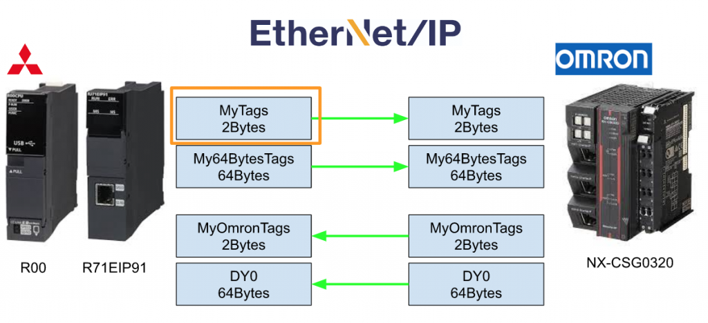
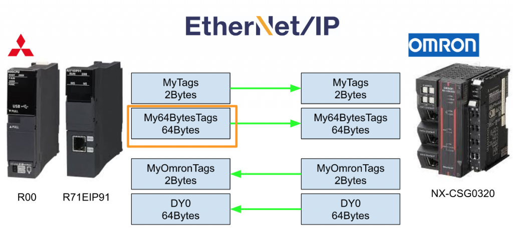
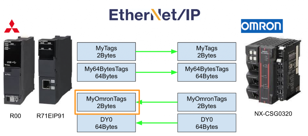
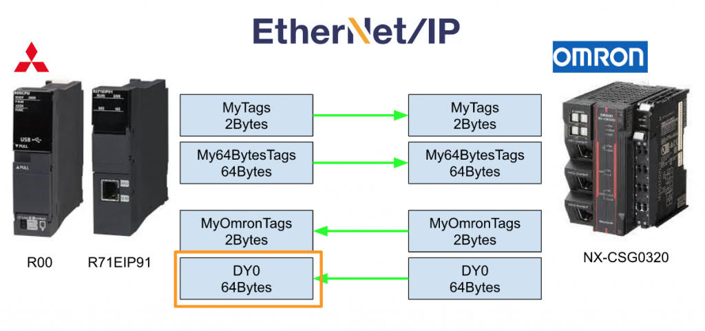
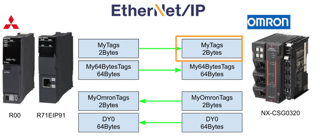
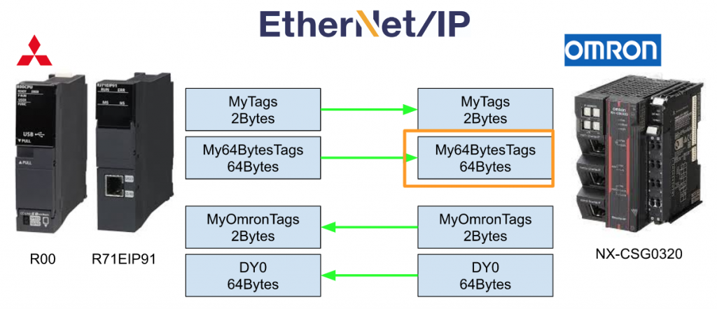
Data Flow
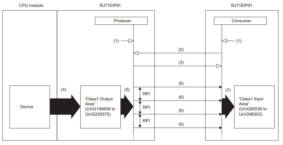
Here is the Flow of RJ71EIP91 Class 1 Tag Communication.
- Set the Ethernet/IP Communication Start request(Y10) to true to start the request
- Establish the Connection
- Wait the response from Consumer
- Transfer the user data from PLC program
- The data will send to the Consumer base on the RPI settings
- Send the data
- Consumer will save the data to buffer memory
Mitsubishi Side
Create new project
Project>New to create a new project.

Choose R00 as the CPU Type, and ST as the Program Language Type.

Add RJ71EIP91
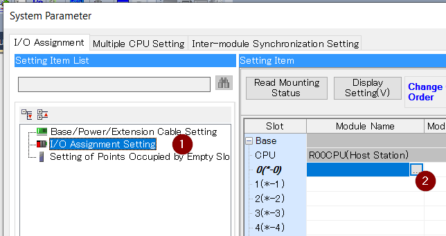
Now we need to insert the RJ71EIP91 in the hardware configuration.Go to Parameter>System Parameter.

Open the I/O Assignment Setting and click Slot0の… Button.
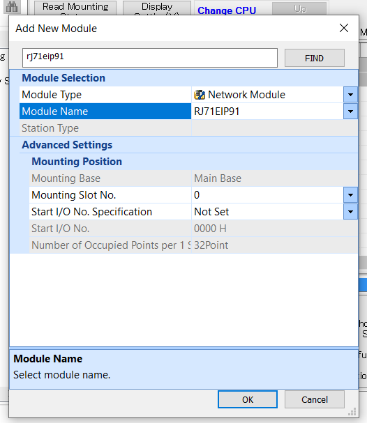
Search RJ71EIP91 in the find field.
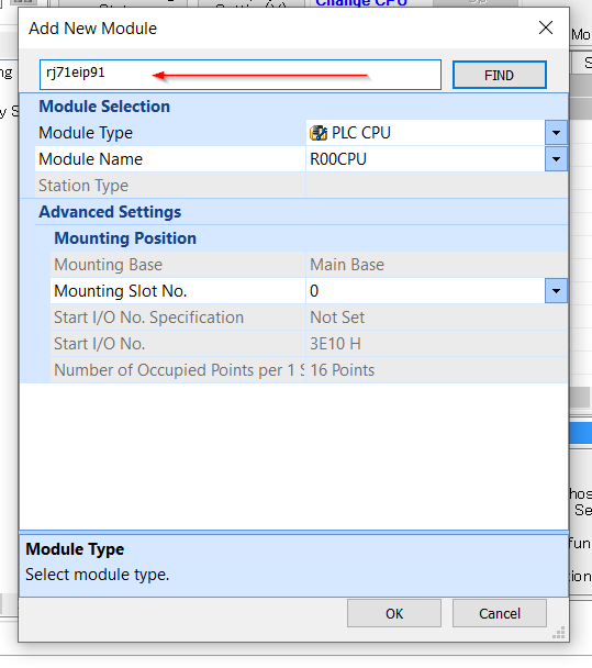
Choose RJ71EIP91 and OK.

click OK to insert the module.
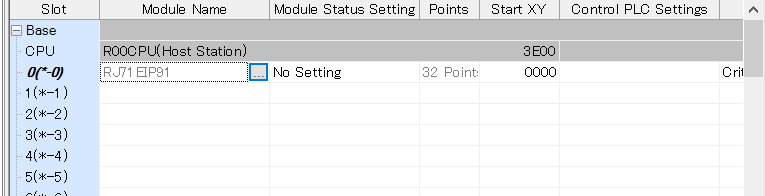
RJ71EIP91 is inserted into your system.
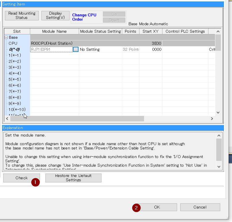
Click the Check button to verify the Hardware Configuration and Press OK to finish.
Add Label
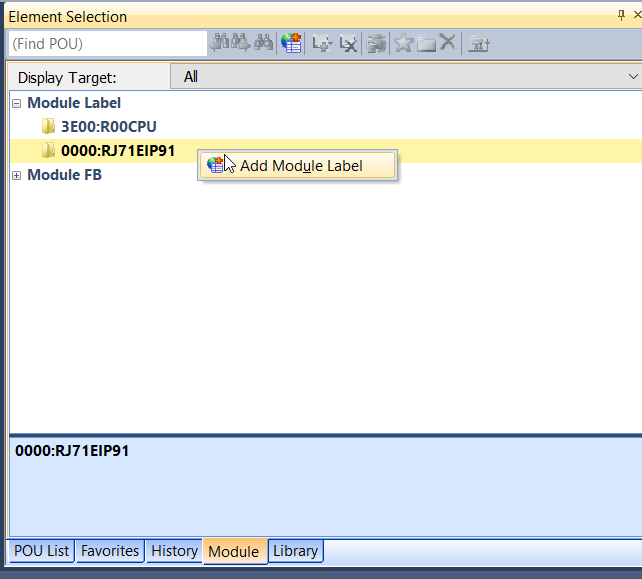
Now we need to add the Module Label of RJ71EIP91.
Go to Element Selection>Module Label>Right Click RJ71EIP91>Add Module Label.
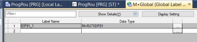
M+Global is inserted.

EIP91_1 is created inside.
Add Function Block
Right Click the FB/FUN>Add New Data to insert the library for RJ71EIP91.
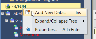
We will delete this Function Block in the end, just let all settings as default and OK.
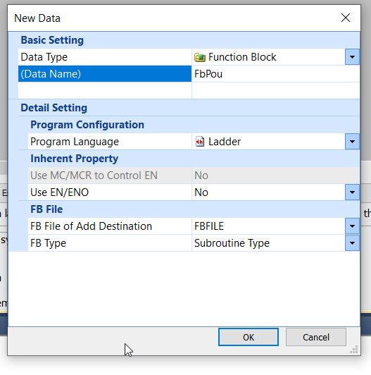
A Dummy FB is created.

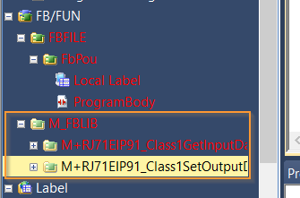
Go to the Element Selection>Module Label>RJ71EIP91 and add the Get,Set Function Block to your project by Right Click>Add to Project.
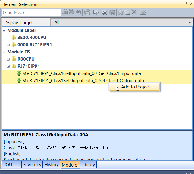
RJ71EIP91 library is inserted in your project.
Now we can delete the Dummy FB.

Set IP
Go to Module Information>0000:RJ71EIP91.

Open the Basic Setting and Configure the IP address of RJ71EIP91 in the IP address field.
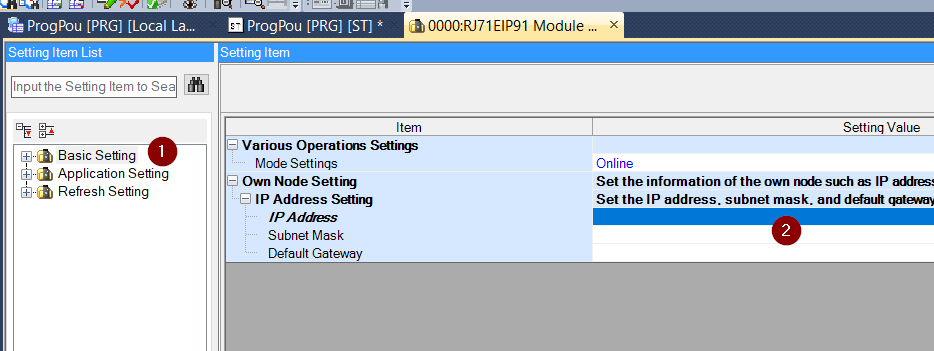
192.168.250.99 is used in my tutorial.
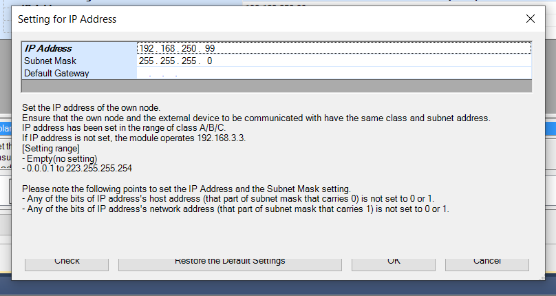
Press the Check parameters to Check all parameters.

Done! No Errors .

Add inside Scan Program
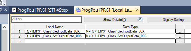
Open the MAIN Program and define the Get/Set instance in the Local Label.

Convert
Go to Convert>Convert to compile your Project.

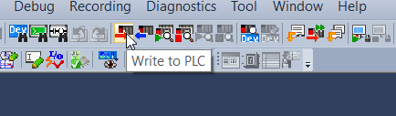
Write to PLC
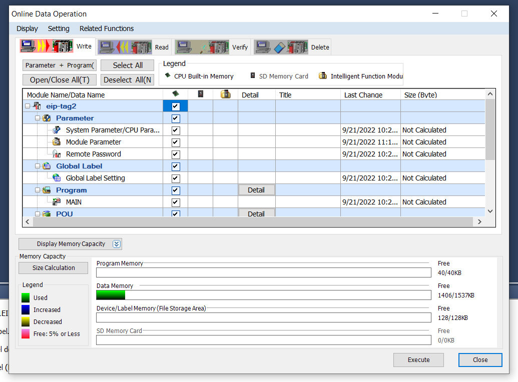
Press the Write to PLC button to download the project to your PLC.
Select all>OK.
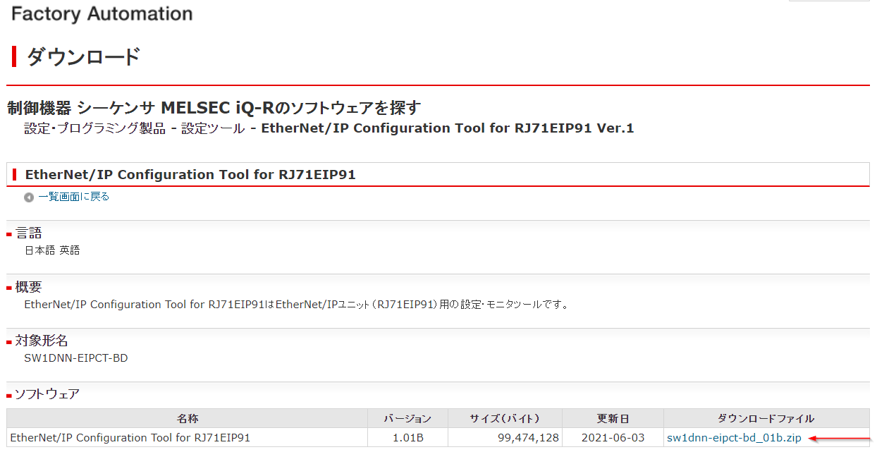
Download and Install Tools
Before we start to configure the RJ71EIP91, please access this link to download the Ethernet/IP Configuration Tools For RJ71EIP91 and install in your PC.
Configure the network
Go to path:
C:\Program Files (x86)\MELSOFT\EIP-CT for RJ71EIP91
to start your Ethernet/IP Configuration Tool for RJ71EIP91.

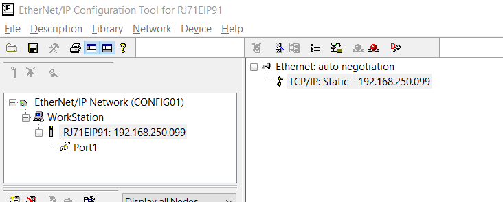
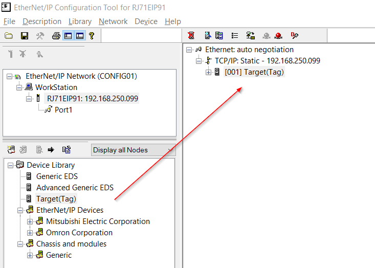
Ethernet/IP Configuration Tool for RJ71EIP91 is started.
Download Omron EDS Files
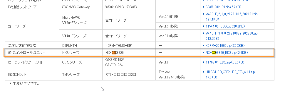
Please access this link to download the EDS File of Omorn NX-CSG320.
https://www.fa.omron.co.jp/member/product/tool/44/eds/download.htm
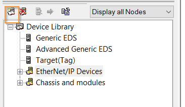
Import EDS File
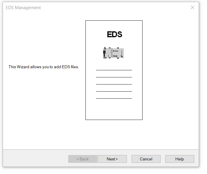
Impot the EDS File.
Next>.
Set the EDS File Path of NX-CSG320 from Browse button and proceed with Next>.

Proceed with Next>. The system shows “EDS exists” because I have already imported the EDS File.
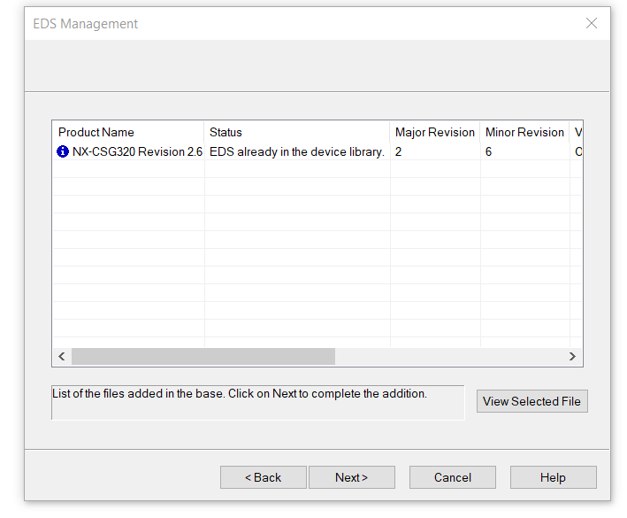
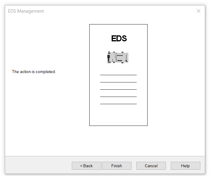
Finish!
NX-CSG320 has been added in the Device library on the left.

Set Module IP
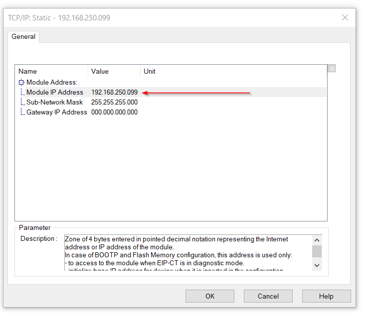
Ethernet>TCP/IP:Staticのところをクリックします。First we need to set the IP of the module.Click on Ethernet>TCP/IP: Static.

Set Module IP and Sub-network according to GXWORKS3.
Add Producer Tags
Now we need to add Producer Tags.
MyTags
First, Let’s create MyTags that occupies 2 Bytes.
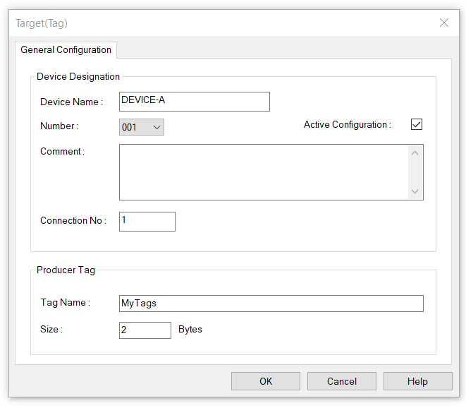
Drop the Target(Tag) right from the Device Library.

The Target (Tag) construction screen will appear and we only need to set the Tag Name and Size.
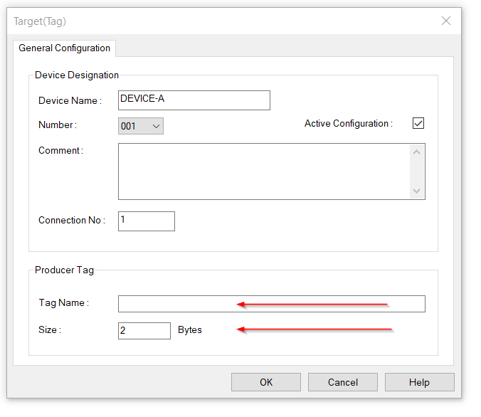
Enter MyTags for Tag Name and 2 Bytes for Size and click OK to complete.
My64BytesTags
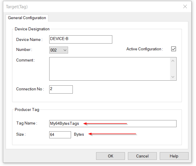
Next, we will create the My64BytesTags that occupies 64Bytes.
Same as before, go to the Device Library and Drop the Target(Tag).
Enter the Tag Name as My64BytesTags and enter 64 in the Size field.
Done!RJ71EIP91 Producer Tags is configured.
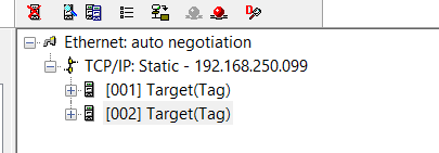
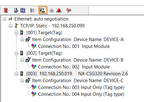
We can overview all conections and their number form the tools.
Add Comsumer Tags
Now we can start to create the Comsumer Tags.
MyOmronTags
MyOmronTags that occupies 2 Bytes will create in this step.
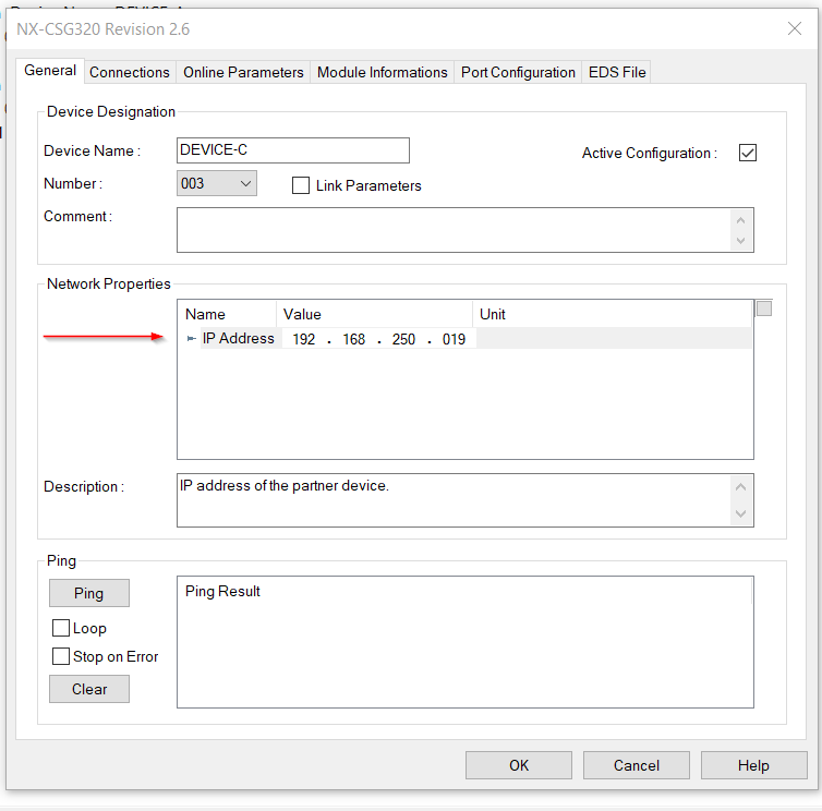
go to Device LibraryからEthernet/IP Devices>Omron Corporation>Communication Adapter and Drop the NX-CSG320 Revision 2.6.

Enter the IP address of Omron NX-CSG320 and 192.168.250.19 is in my case.
Go to the Connection Tag>Remove the Default Connection.
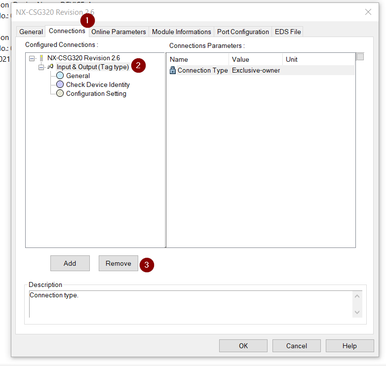
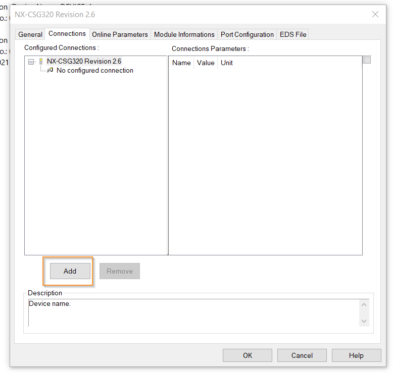
Now we can add a new connection.
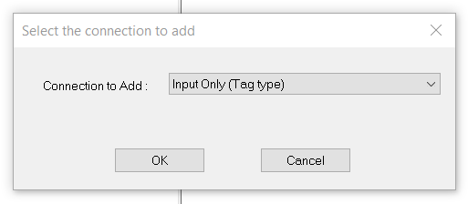
Select Input Only(Tag Type) as the Connection Type and OK.
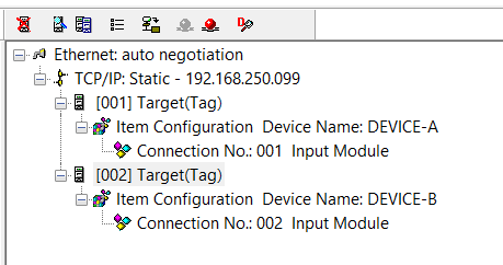
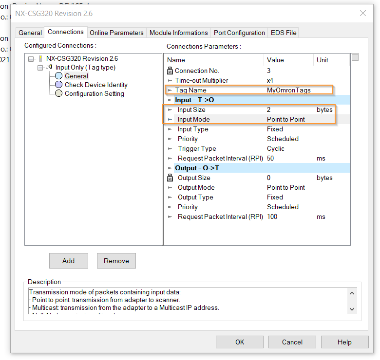
Go to the General Tab and enter the Tag name.
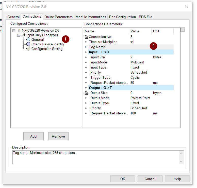
The Consumer Tags that occupy 2 Bytes (MyOmronTags), so we will enter the Input Size is 2 Bytes, as Point to Point is the Input Mode. In other words, the RJ71EIP91 is now outputting data from a 2-byte Tag called MyOmronTags.
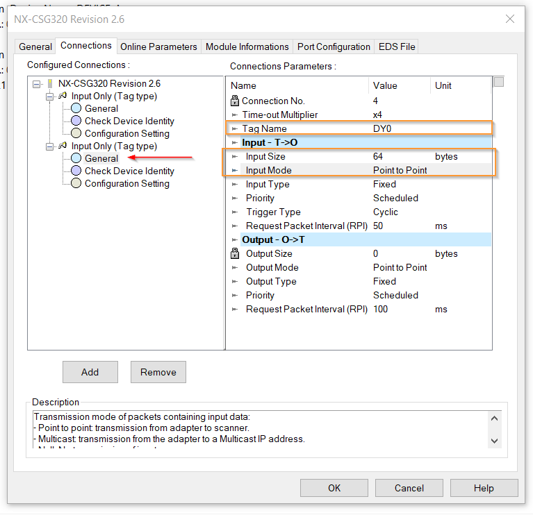
DY0
DY0 Tag is occupied with 64 Bytes.
Click the Add button from the same Connection as before to add a Connection.

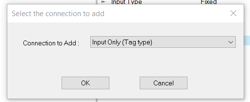
Select Input Only(Tag type)>OK.
Open the Connections Tab, and enter the TagName is DY0 – with 64bytes Input size with Point to Point Input Mode.
we Configured 4 connections in the RJ71EIP91 Modules, Connection1/Connection2 is Producer Tags and Connection3/Connection4 is Consumer Tags.

Download the Configuration
Click the Green Button to change the tool to online mode.

Click the Orange marked button to download the Configuration.
Popup is shown and Download.

Done!

Program
Now we can create the PLC program on the GXWORKS3 side.
Local Label
Let’s define the local variable in the program.
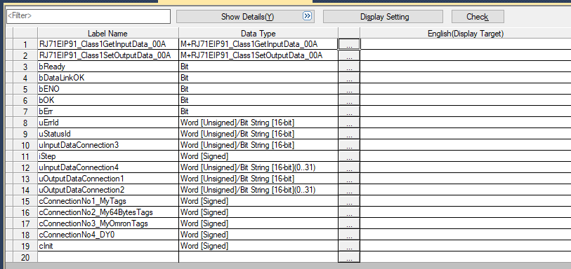
Code
Here is the code.
- Check if the module is ready.
- If there is an error in the module, apply a reset flag to automatically reset it.
- If the module is Ready, the communication set the request Flag to True.
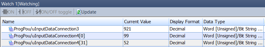
- Finally, branch at CASE and if Case=3,4, use RJ71EIP91_Class1GetInputData_00A library to get Tag data. If Case=1,2, use RJ71EIP91_Class1SetOutputData_00A library to write Tag data.
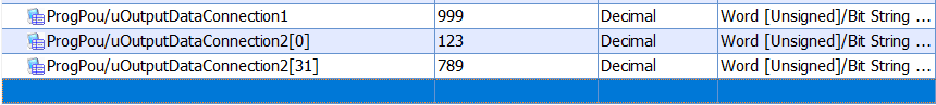
| //Ready bReady:=EIP91_1.bSts_ModuleReady AND EIP91_1.bSts_CommunicationReady AND NOT EIP91_1.bSts_ModuleError; //Auto Reset EIP91_1.bSet_ModuleErrorClearRequest:= EIP91_1.bSts_ModuleError; //Send the Startup Request EIP91_1.bSet_CommunicationStartupRequest:=bReady; CASE iStep OF cConnectionNo3_MyOmronTags: bDataLinkOK:=EIP91_1.bnSts_Class1DuringDataLink_Connection_D[3]; RJ71EIP91_Class1GetInputData_00A( i_bEN:= bDataLinkOK ,i_stModule:= EIP91_1 ,i_uConnectionNo:= 3 ,o_bENO=> bENO ,o_bOK=> bOK ,o_bErr=> bErr ,o_uErrId=> uErrId ,o_uStatusId=> uStatusId ,o_uInputData=> uInputDataConnection3 ); IF bOK THEN iStep:=cConnectionNo4_DY0; bOK:=FALSE; END_IF; cConnectionNo4_DY0: bDataLinkOK:=EIP91_1.bnSts_Class1DuringDataLink_Connection_D[3]; RJ71EIP91_Class1GetInputData_00A( i_bEN:= bDataLinkOK ,i_stModule:= EIP91_1 ,i_uConnectionNo:= 4 ,o_bENO=> bENO ,o_bOK=> bOK ,o_bErr=> bErr ,o_uErrId=> uErrId ,o_uStatusId=> uStatusId ,o_uInputData=> uInputDataConnection4[0] ); IF bOK THEN iStep:=cConnectionNo1_MyTags; bOK:=FALSE; END_IF; cConnectionNo1_MyTags: uOutputDataConnection1:=999; bDataLinkOK:=EIP91_1.bnSts_Class1DuringDataLink_Connection_D[1]; RJ71EIP91_Class1SetOutputData_00A( i_bEN:= bDataLinkOK ,i_stModule:= EIP91_1 ,i_uConnectionNo:= 1 ,i_uOutputData:= uOutputDataConnection1 ,o_bENO=> bENO ,o_bOK=> bOK ,o_bErr=> bErr ,o_uErrId=> uErrId ,o_uStatusId=> uStatusId ); IF bOK THEN iStep:=cConnectionNo2_My64BytesTags; bOK:=FALSE; END_IF; cConnectionNo2_My64BytesTags: uOutputDataConnection2[0]:=123; uOutputDataConnection2[31]:=789; bDataLinkOK:=EIP91_1.bnSts_Class1DuringDataLink_Connection_D[1]; RJ71EIP91_Class1SetOutputData_00A( i_bEN:= bDataLinkOK ,i_stModule:= EIP91_1 ,i_uConnectionNo:= 2 ,i_uOutputData:= uOutputDataConnection2[0] ,o_bENO=> bENO ,o_bOK=> bOK ,o_bErr=> bErr ,o_uErrId=> uErrId ,o_uStatusId=> uStatusId ); IF bOK THEN iStep:=cConnectionNo3_MyOmronTags; bOK:=FALSE; END_IF; cInit: iStep:=cConnectionNo3_MyOmronTags; END_CASE; ; |
OMRON Side
Next, let’s move on to the Omron NX-CSG320.
IP Address
For the IP configuration, Port2A is used, so we will directly specify the IP address from the Rotary Switch in the project.

If Rotary Switch 2 is not 0, the IP address will be set to 192.168.250.x. In this case, the switch is set to 13, which is 13 in hexadecimal and 19 in decimal. Therefore, the IP address will be 192.168.250.19.

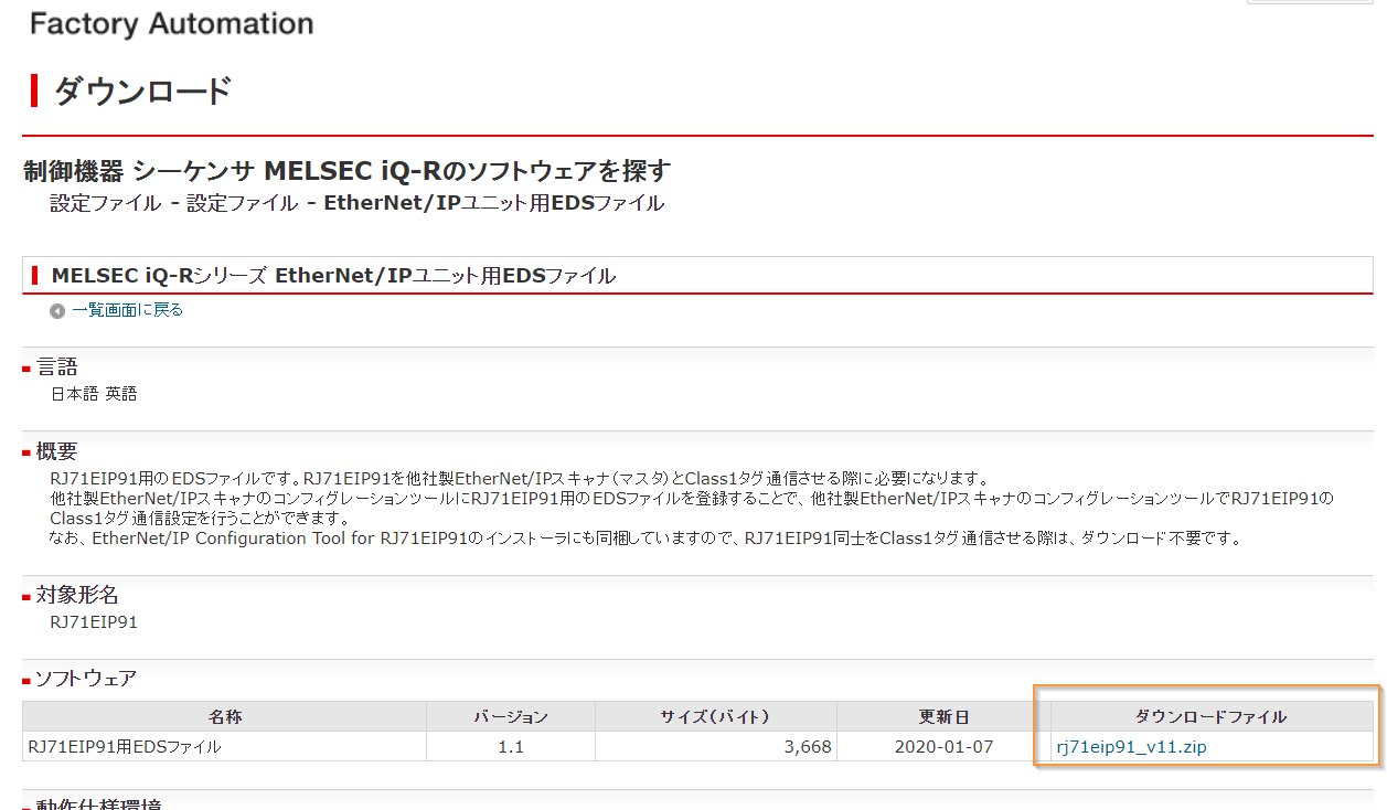
Download Mitsubishi EDS File
You need to import the Mitsubishi RJ71EIP91 module into the Omron Sysmac Studio tool. Please download the EDS file for the RJ71EIP91 module from the link below.
Ethernet/IP Setting
Launch Sysmac Studio and import the hardware data of the CPU. Then, click on “Tools” and select “EtherNet/IP Connection Settings”.

The screen displaying the IP addresses for Port1 and Port2 will appear.
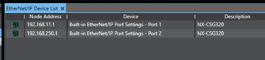
Select Port 2, which corresponds to 192.168.250.1, and right-click on it to select “Edit”.

This will bring up the Ethernet/IP tag configuration screen.

Import EDS Files
First, import the EDS file for the RJ71EIP91. Click on “Toolbox” and then right-click to select “Display EDS Library.”
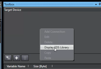
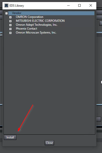
To install a new EDS file, go to the EDS Library screen by right-clicking on the Toolbox and selecting “Display EDS Library”. Then click on the “Install” button and select the EDS file that you want to install.
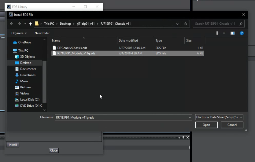
Select the downloaded EDS file and click “Open”.
Yes.
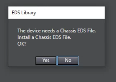
次はChassis.edsを選び>Openします。

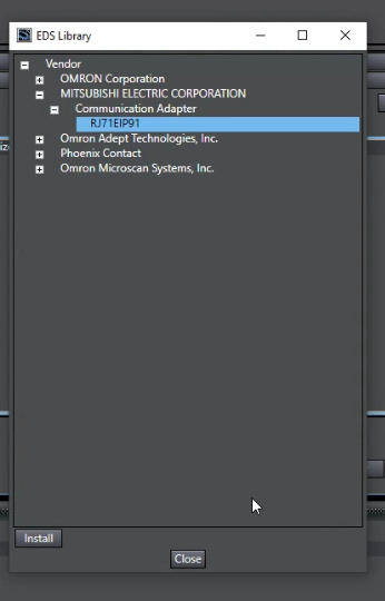
You will be able to select Vendor>MITSUBISHI ELECTRIC CORPORATION>Communication Adapter>RJ71EIP91. Click Close to exit.
Add RJ71EIP91
Next, you will add a target device to the project.
Click on the “Add a target device” button with the + sign.

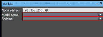
Node address
The Toolbox screen will change, and you should first set the Node address. Please set the IP address to match the IP address you set in GX Works3 earlier. So, this time we will set it to 192.168.250.99.
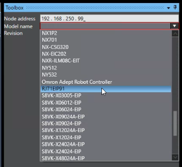
Model name
The Model Name should be set to the previously added RJ71EIP91.
Revision
Revision can be set to 1.

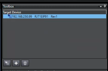
Click on the “Add” button to add the target device to the project.
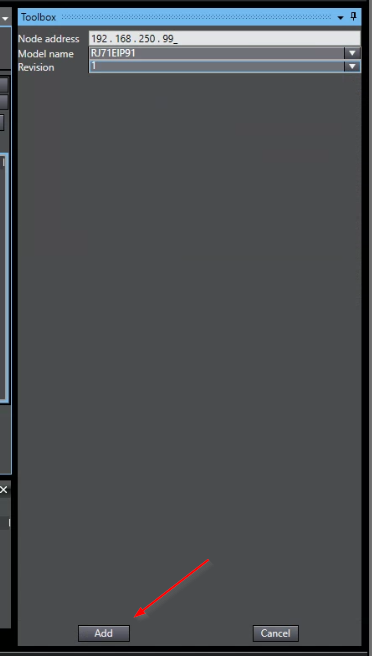
The RJ71EIP91 with IP address 192.168.250.99 has been added to the project.
Add Global Variables
Next, we will define global variables that will be used for Producer Tags and Consumer Tags. Click on Programming>Data>Global Variables.

Add Tags
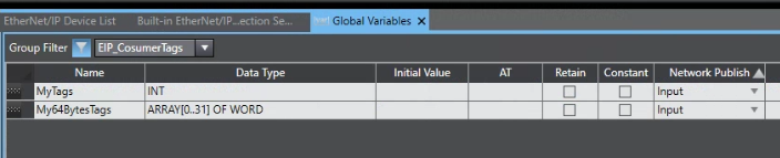
Let’s define the “MyTags” global variable. The data type should be INT, and the attribute should be Input.

Let’s define My64BytesTags. The Data Type should be ARRAY[0..31] OF WORD and the attribute should also be set as Input.
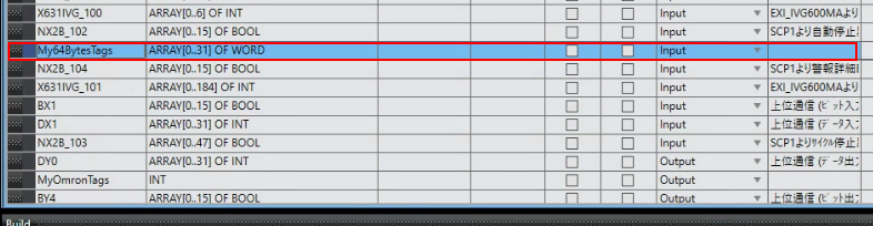
You should define MyOmronTags as an INT data type with Output attribute.

DY0 is the existing variable and there is no need to make any changes to it.

Add to Groups
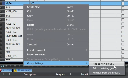
To make it easier to view, let’s create a variable group. Right-click on MyTags and select “Group Settings” and then “Add to new group.”
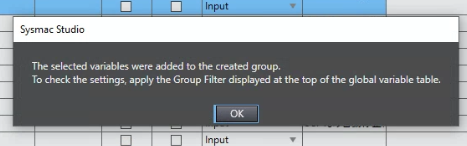
Enter the group name and click OK.

OK.
Right-click on My64BytesTags and select “Group Settings” then choose “Add to existing group”.

Select the previously added group and click OK.

Once you add a group, you can use the Filter function. Select the EIP_CosumerTags group you added earlier from the drop-down list, and click the Group Filter button.

The variables belonging to the selected group will now be displayed using the Group Filter button.
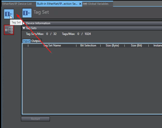
Tag Set
Go back to the Ethernet/IP Settings screen and click on the “Tag set” button at the top to register the variables defined in the Global Variables for Ethernet/IP tag communication.
Click the “Registration All” button on the right side.

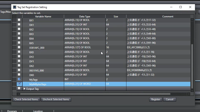
The variables defined as Input and Output tags are divided into two groups: Input Tag and Output Tag. Uncheck the checkboxes and select All Unselect.

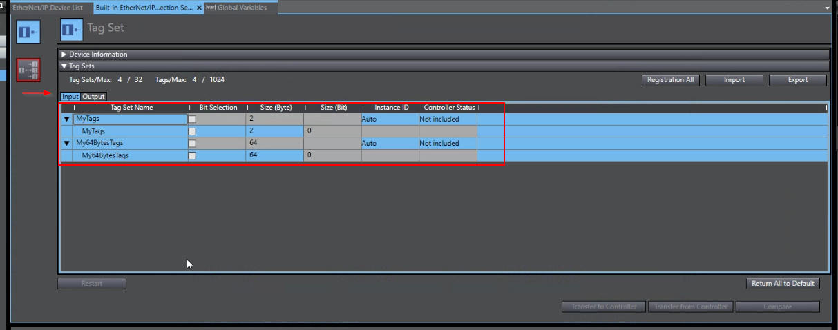
Check the MyTags and My64BytesTags in the Input Group.
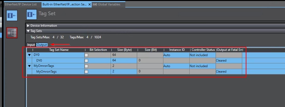
Put DY0 and MyOmronTags Checkbox in Output Groups.
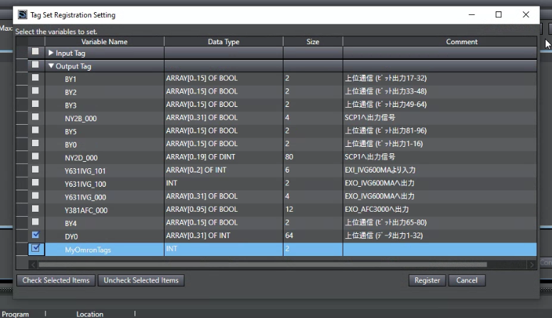
Register with the Register button.

If you look at the Input Tab, you will see MyTags and My64BytesTags.
If you look at the Output Tab you will see DY0 and MyOmronTags, it means that registration is OK.
Configure Connection
Since the Producer Tag has already been created in the previous Tag Set step, only the Consumer Tag is needed to add manually.
MyTags
It starts with MyTags which occupies 2 Bytes.
Click the Connection button to switch the screen.
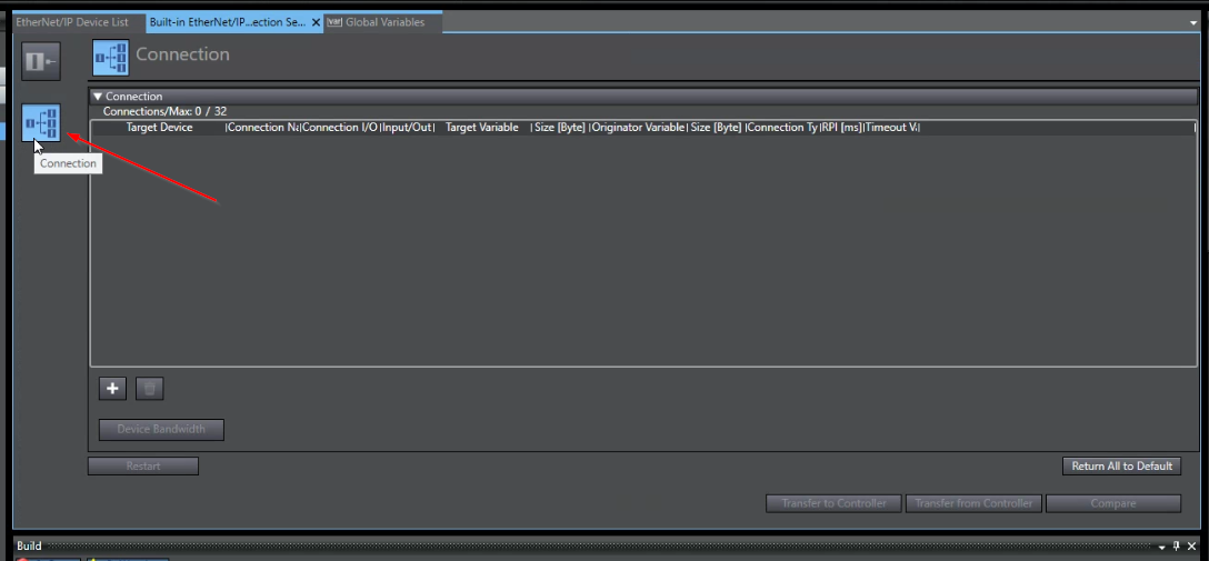
First, drop the RJ71EIP91 added from the Toolbox to the Connection Field.
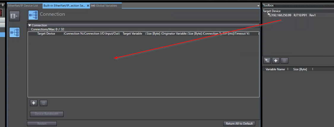
Tag Connection is inserted.
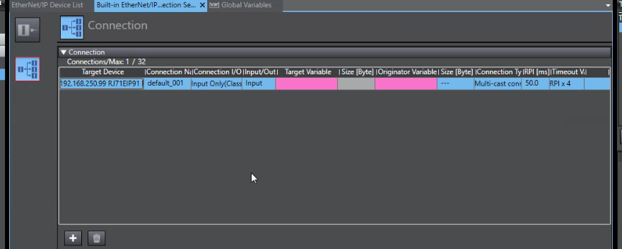
Please configure the name same as what you set in the RJ71EIP91 Configuration Tools.
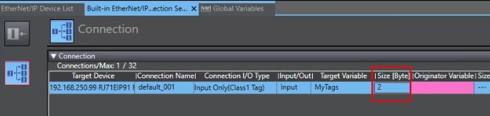
In this case, MyTags is my Tag Variable.
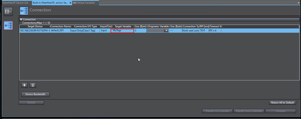
Enter the Size of your Tag Variable.In this tutorial, 2 bytes are used.
Select the drop list in the “Originator Variable” Field.

Please select MyTags here. This variable is what you defined in the Global Variable list.
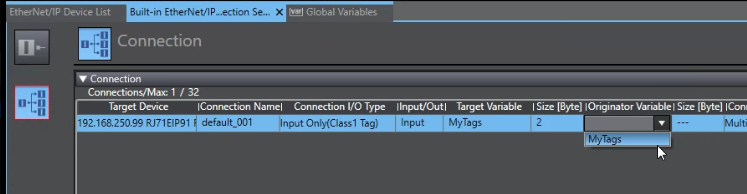
Done.

My64BytesTags
Finally I will show you how to configure the 64 bytes Tag – “My64BytesTags”.
This time I will press the + button to insert a connection.
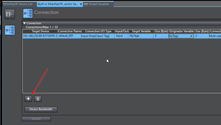
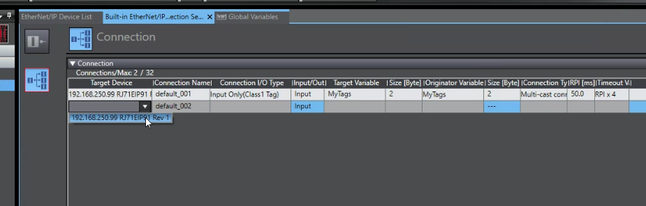
An empty connection is created in your network.

Choose RJ71EIP91 as your Target Device.
Enter “My64BytesTags” as your Tag name, which you configured in the RJ71EIP91 Configuration Tool.
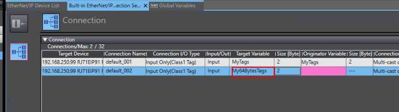
Set the Size as 64 Bytes.

Select “My64BytesTags” from the Originator Variable Drop List.
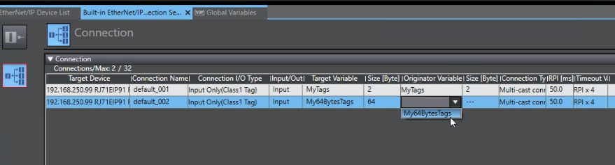
Done.

Finally please change the Connection Type to Point to Point.

Download
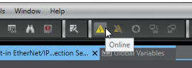
Click the Online button.
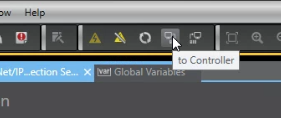
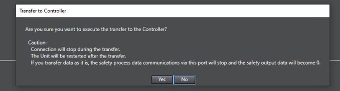
Press “To Controller” to download the project to your CPU.
Execute it.

Yes.
Done.

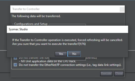
Finally , you need to go back to the previous screen to Transfer the Ethernet/IP Setting to CPU by Clicking the “Transfer to Controller” Button.

Yes.
Transfer to Controller is shown and please wait a second..

Result
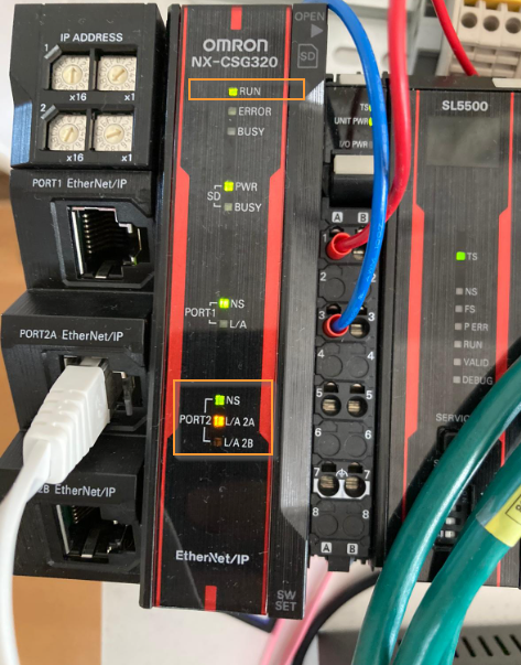
You can see RUN/MS/NS , both these LEDs are in green.

On the Omron Side, the RUN/NS LED is also green in the NX-CSG320 .
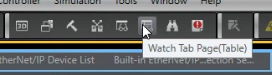
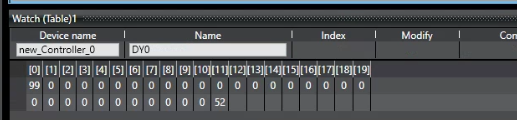
Let’s check the array data first. Click the Watch Tab Page(Table) in Sysmac studio.
You can just enter the array name in the Device Name field.

The value is the same as the RJ71EIP91 Side.
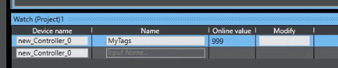
Now we can check the Producer Tags in the OMRON Side.

The value are same!
Source Project
Please download the sample project from my github:
https://github.com/soup01Threes/GXWROKS/blob/main/RJ91EIP_CSG0320_Demo.zip