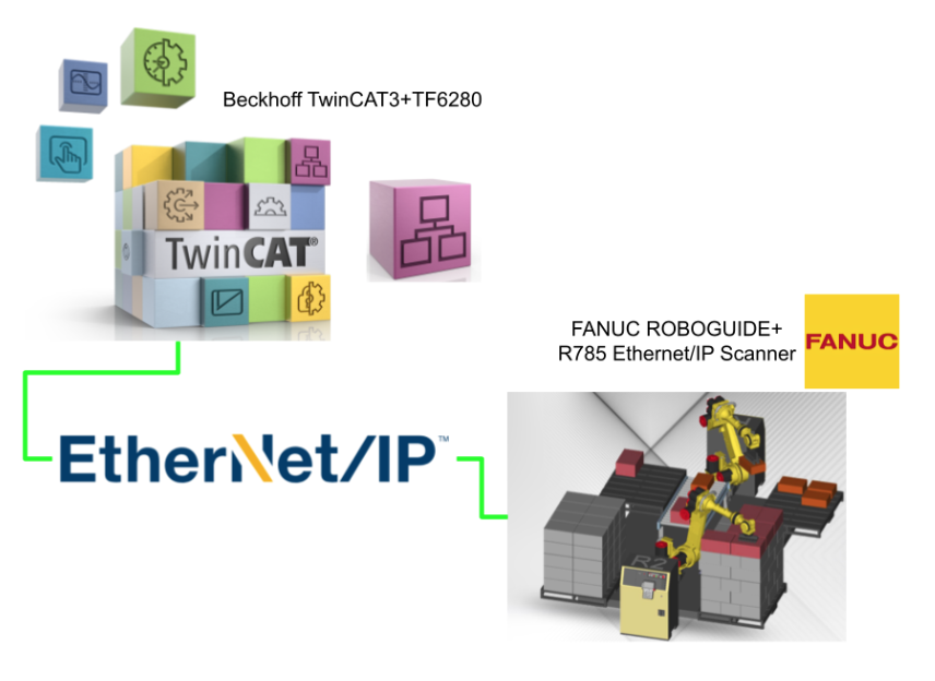
In this article, we will start up an Ethernet/IP Adapter with Beckhoff TwinCAT3 and TF6280, then connect it to Ethernet/IP Scanner with R785 Options on the FANUC ROBOGUIDE side.Also, the IO data mapping method on the FANUC ROBOGUIDE side is explained.
Step by Step、From Zero To Hero。
Let’s get started!
Implementation1
Beckhoff Side
First, build the Ethernet/IP Adapter from the Beckhoff side.

Add Ethernet/IP Adapter
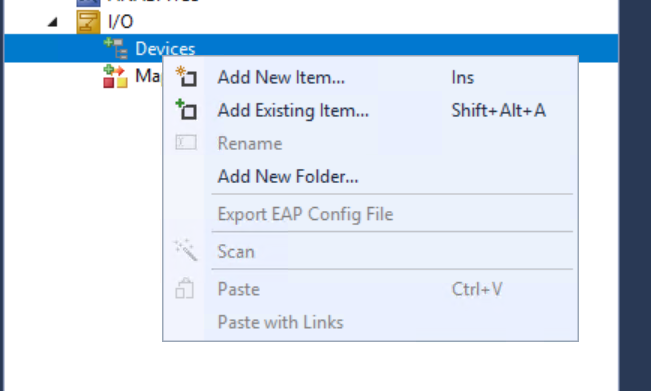
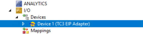
To add an Ethernet/IP Adapter, go to Devices>Right click>Add New Item.
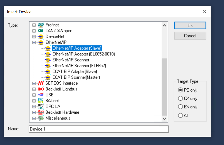
Select EtherNet/IP Adpater(Slave) >Ok.
Done!
Configure Adapter
To configure the Network Interface to be used by the Ethernet/IP Adapter, open the Adapter Tab and click Search.
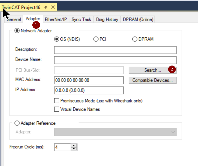
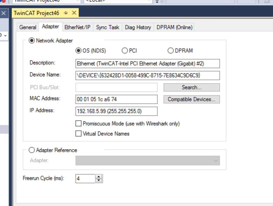
The Network Interface that can be used by the PC on which TwinCAT Runtime is currently installed is listed, and the user selects the Interface to be used by the application and confirms with >Ok.
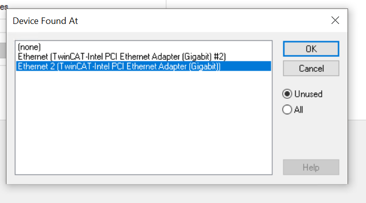
Done!
Sync Task
Next, click on “Create new I/O Task” to define the Sync Task for Ethernet/IP.
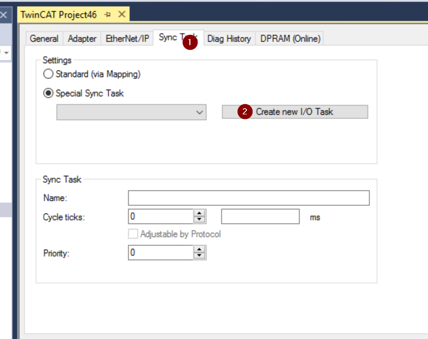
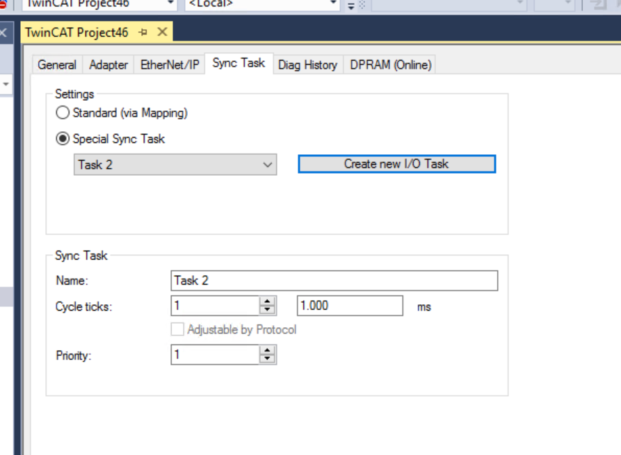
Set the task name.
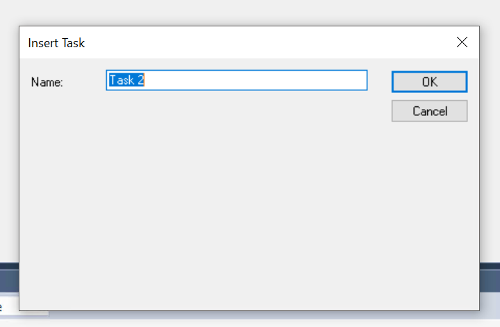
Done!Then you can set up Cycle Ticks according to your application.
IP Address
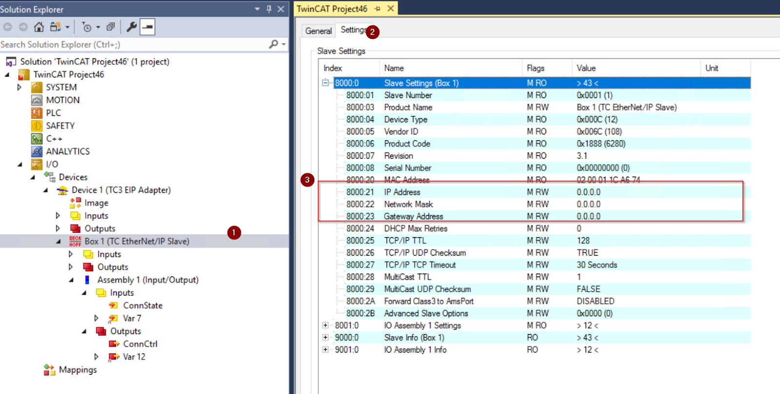
Open Box1>Settings and set IP Addresses and Network Mask of your Ethernet/IP Adpater at 8000.21 and 8000.22. Be careful that this IP address does not conflict with the IP addresses of other devices.
Configure the Slave
Next, configure the Ethernet/IP Slave.
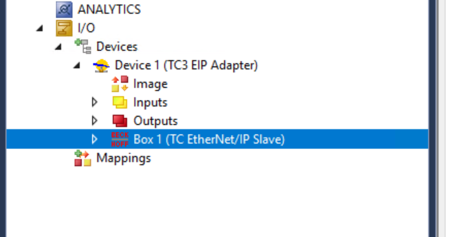
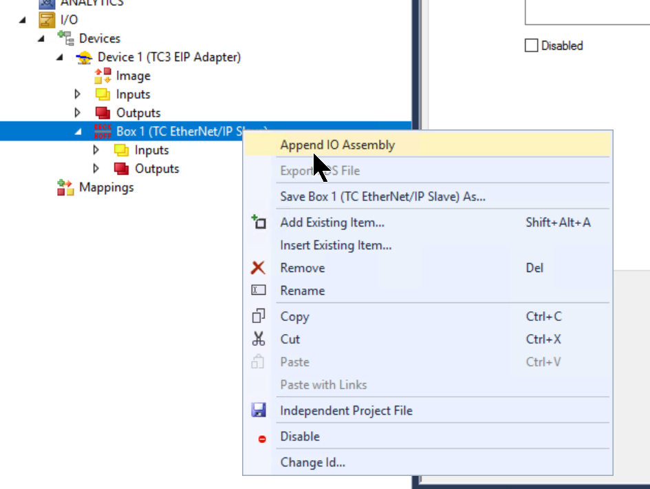
Add IO Assembly
Click on Box1>Right click>Append Io Assembly to set up the Assembly for the Ethernet/IP Adapter.
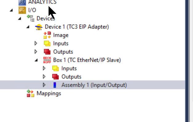
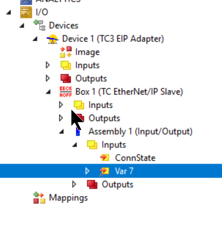
Assembly1 has been added.
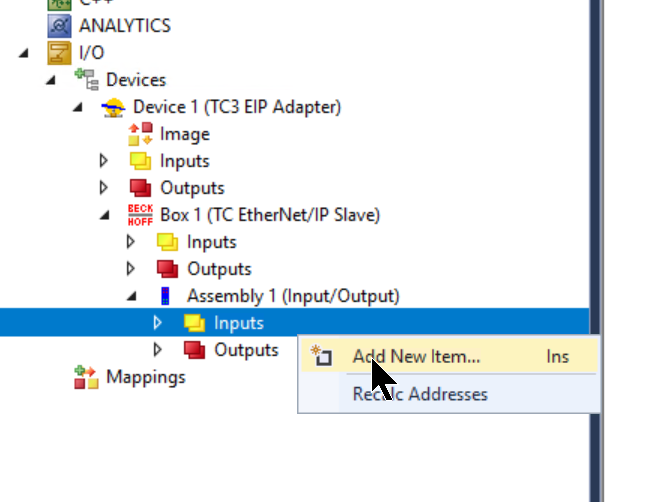
Add Inputs
Inputs>Add New Item to define the input data for the Ethernet/IP Adapter (the output of FANUC ROBOGUIDE).
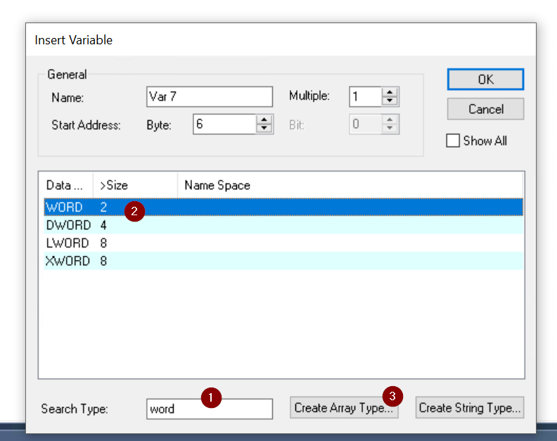
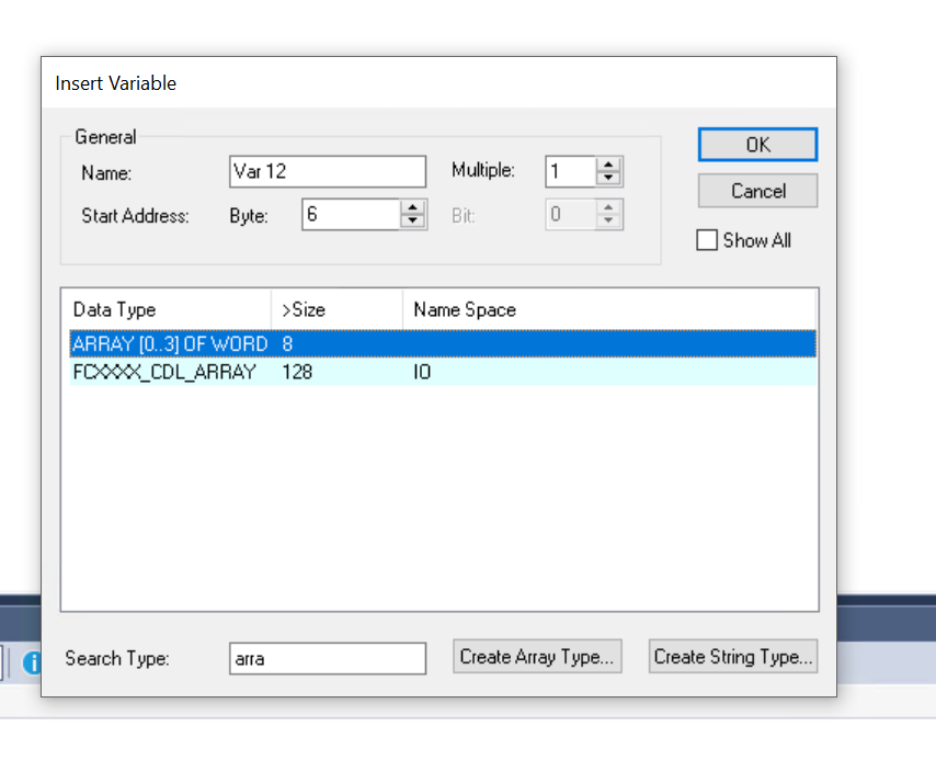
The Insert Variable screen is now displayed.

In this case, we will define 4-word input data, so enter Word for Search Type>Select Word>Click Create Array Type to define the array data type.
The screen will change to the Array creation screen.
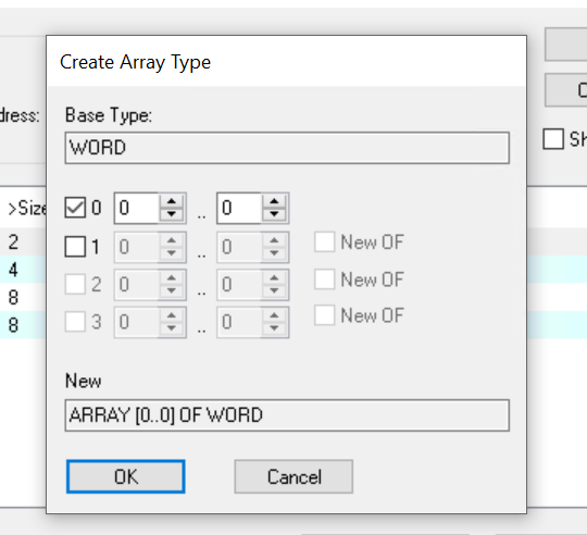
As I mentioned earlier, this article will use 4Word data, and set the size of the picture and array to 0…3.
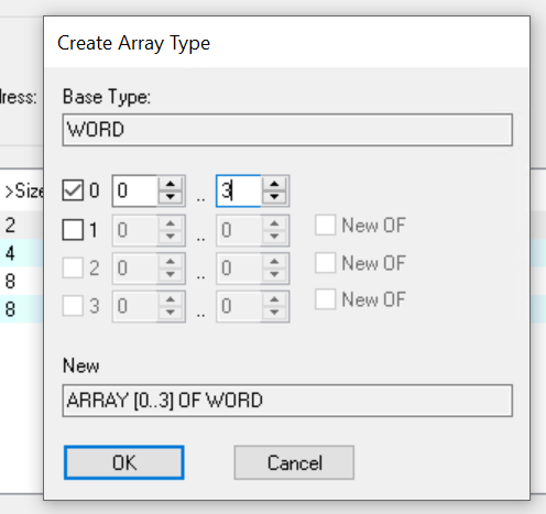
Now that the array data type is defined, select ARRAY[0..3]OF WORD and proceed with >Ok.
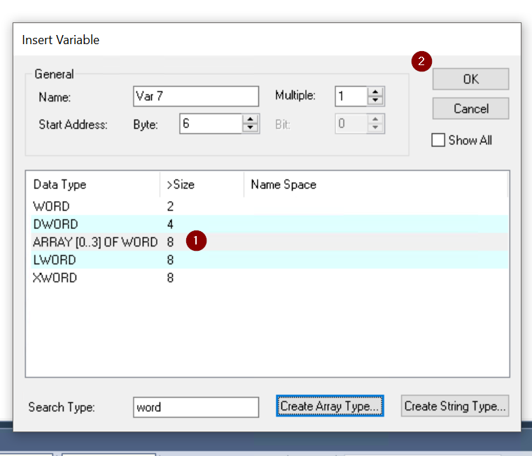
Done!
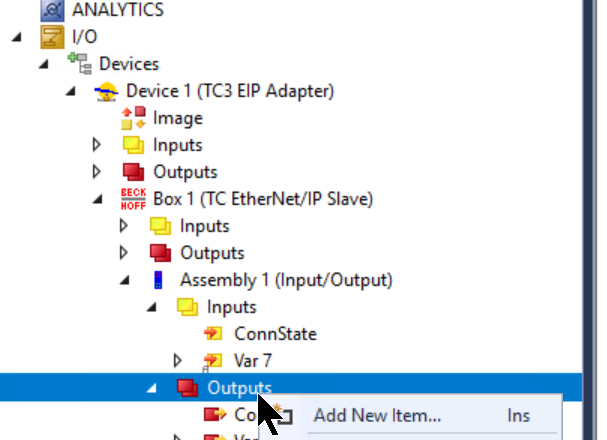
Add Outputs
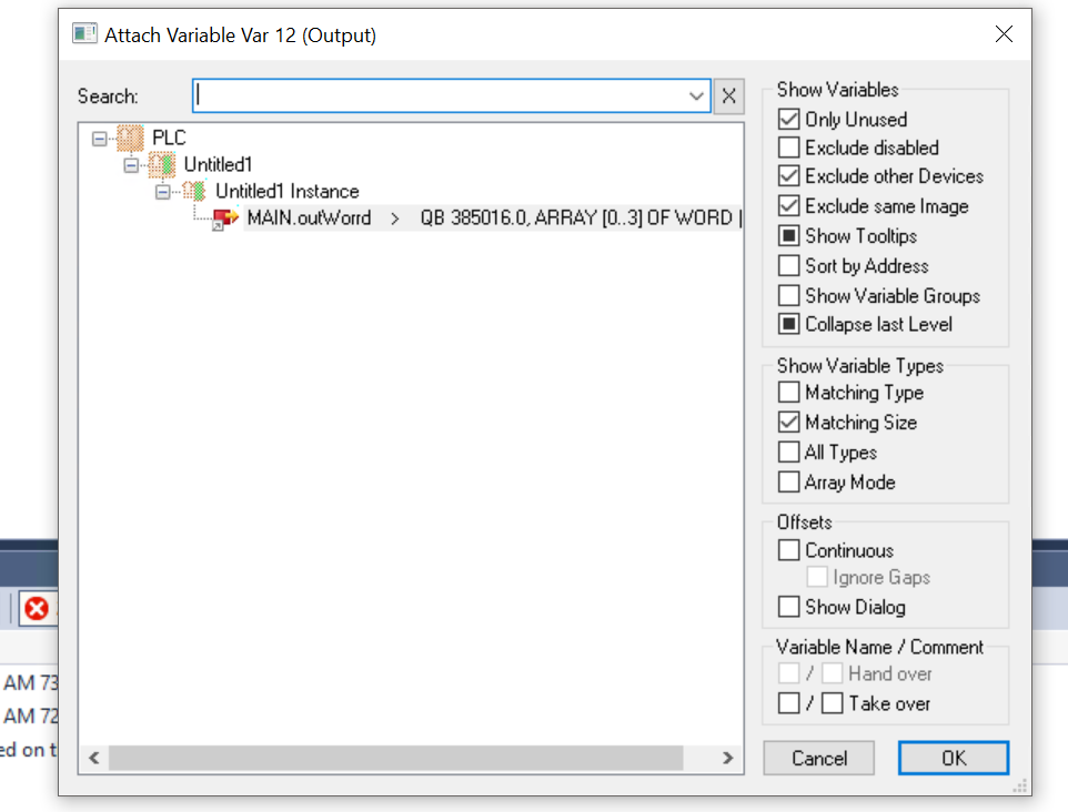
Next, to define output data, click Outputs>Right Click>Add New Item.
Select the ARRAY[0..3]OF WORD you just added and >Ok.
Add PLC Project
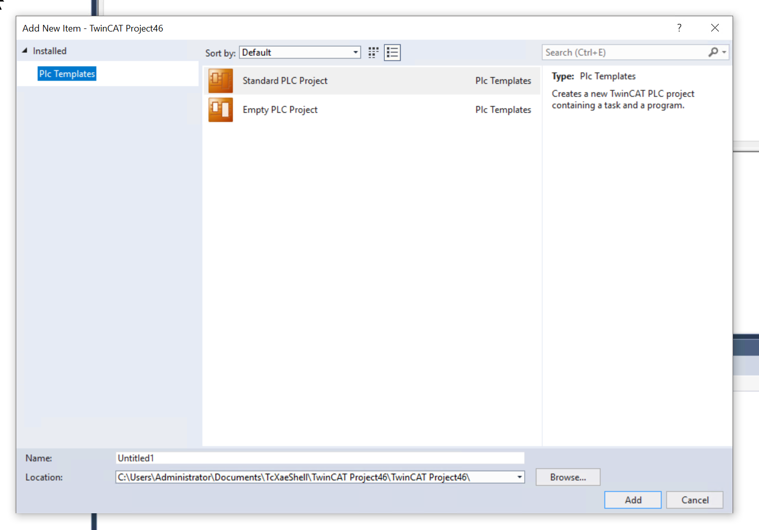
Next, to add a PLC project, go to PLC>right click>Add New item.

Select Standard PLC Project>Add.
MAIN Program
In this article, we will define only Process data for the MAIN program, and in the next article, we will be able to work with a simple robot program.
| PROGRAM MAIN VAR inWord AT %I*:ARRAY[0..3]OF WORD; outWorrd AT %Q*:ARRAY[0..3]OF WORD; in,out:ARRAY[0..3]OF WORD; END_VAR in:=inWord; outWorrd:=out; |
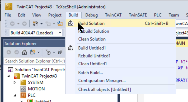
Build
Compile the project under Build>Build Solution.
Link IOs
Now, to link variables in User Program to Process IO, go to Inputs>Variables>Right click>Change Link.
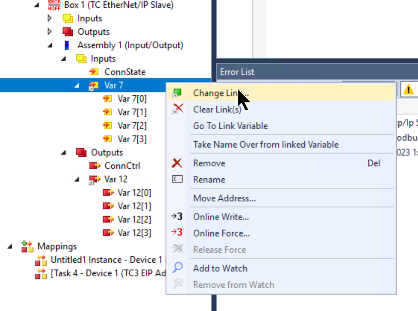
Let’s set the variables we just defined in the MAIN program.
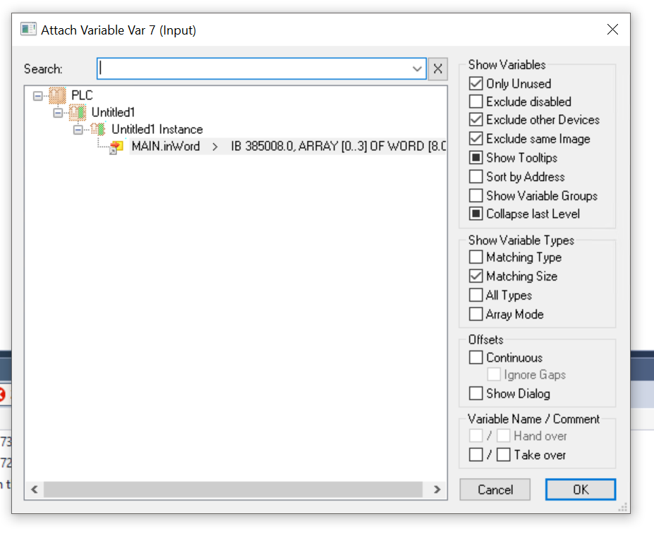
The same operation should be used for the output data to link variables in the User Program.
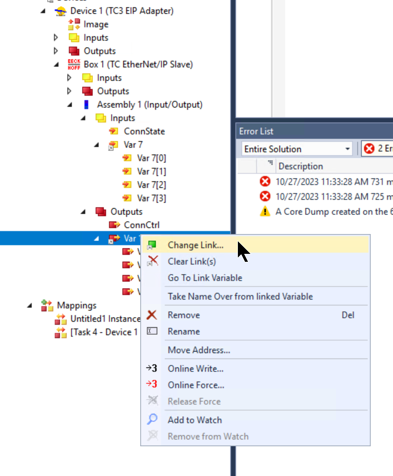
Let’s set it to a variable defined in the User Program.
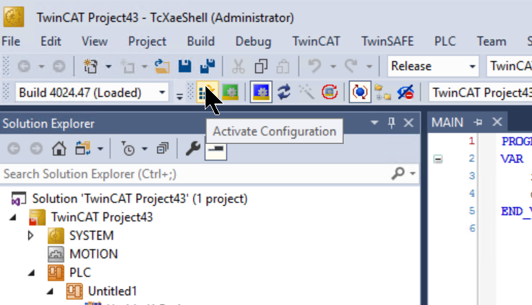
Activate Configuration
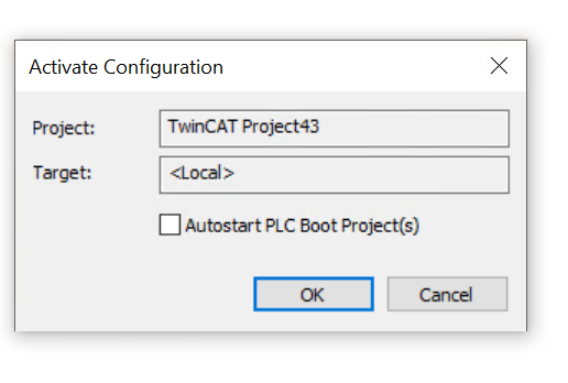
Finally,Click the Activate Configuration to download the Hardware Configuration to Runtime.
Proceed with Ok.
If there are not enough licenses, proceed with Yes.
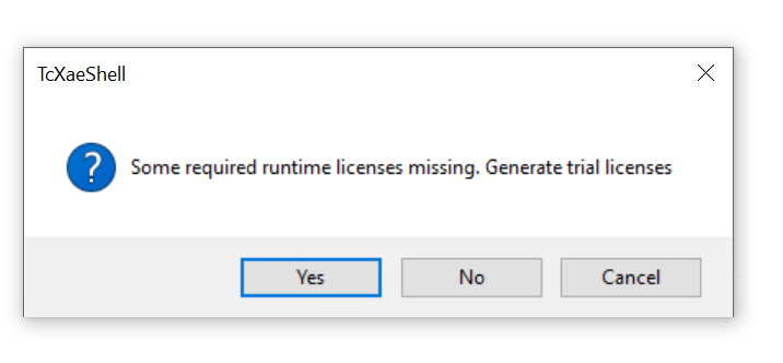
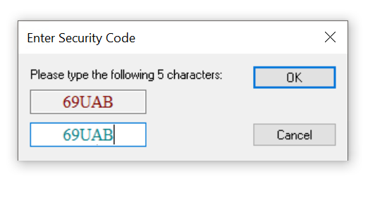
Enter the Security Code,Then a Trial license can be generated automatically.
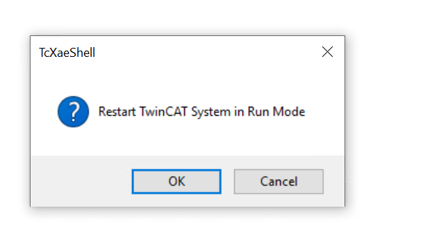
Switch TwinCAT to Run Mode with Ok.
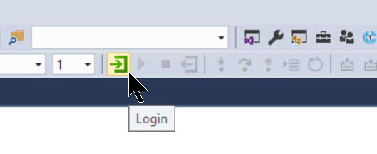
Login
Click the Login button to download the program.
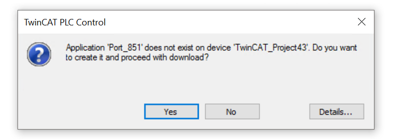
Proceed with Yes.
Run
Finally, click the Run button to start the program.
Then the Beckhoff side is set up.

FANUC Side
The next step is to set up the FANUC side.

New Project
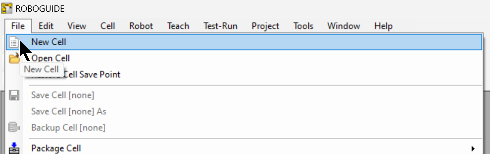
Click File>New Cell to create a new program in ROBOGUIDE.
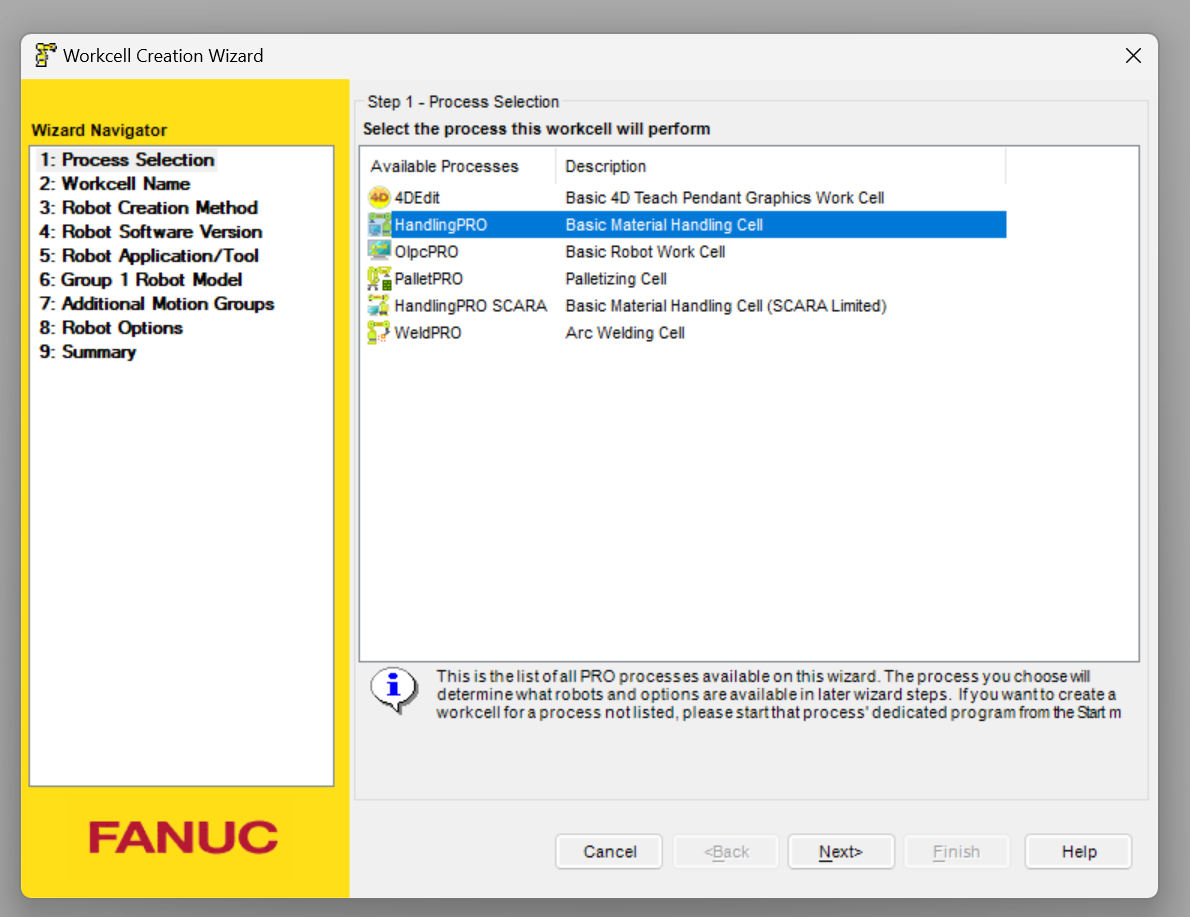
Match the application to the Process Selection screen.
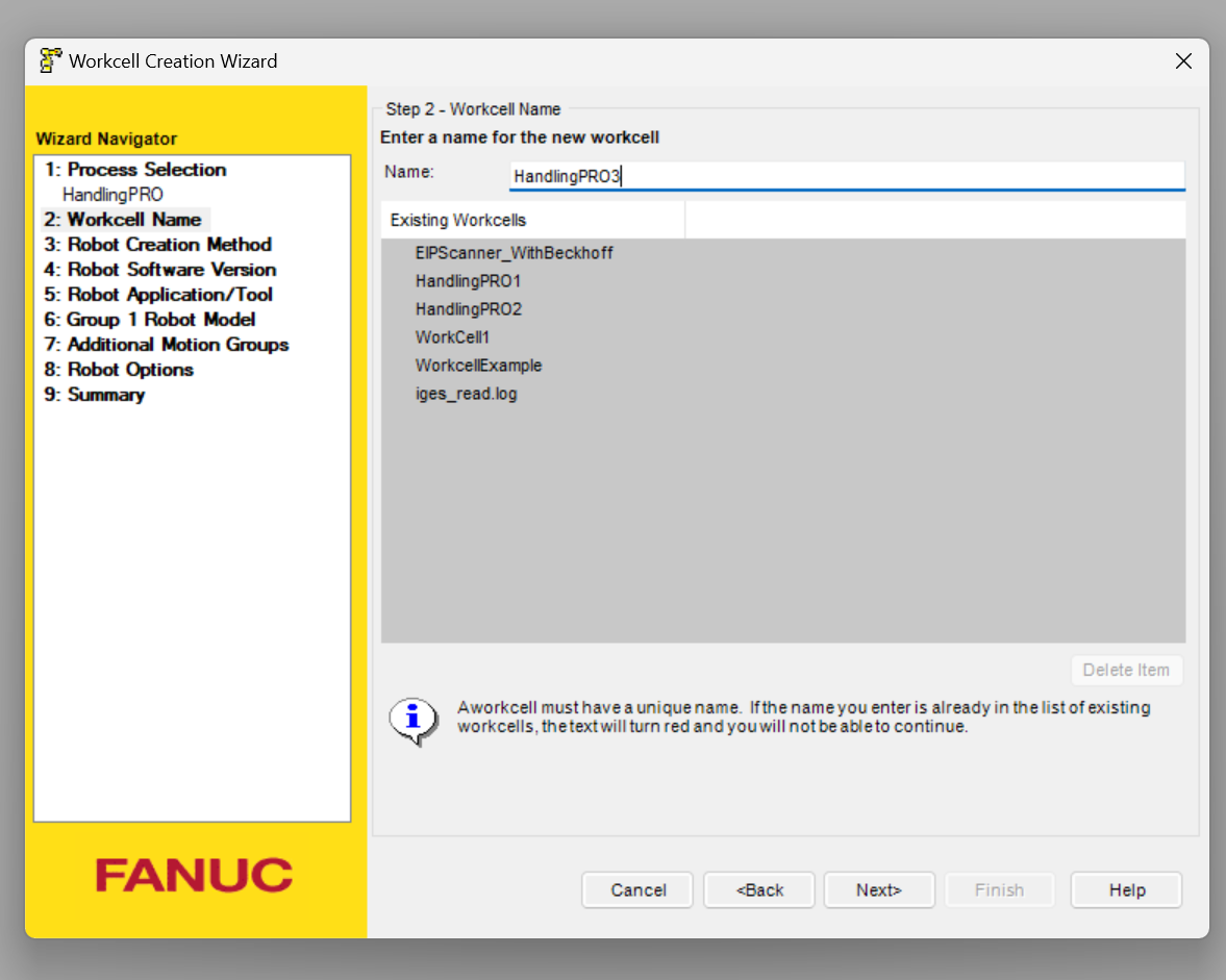
Set the workcell name and go to Next>.
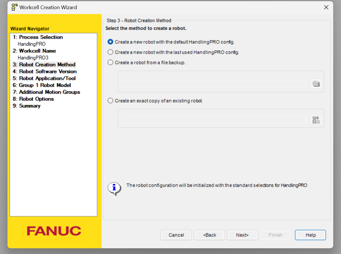
Create a new robot Configuration.
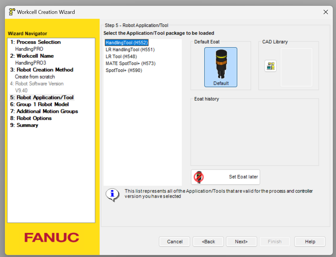
Tools should also be configured to match your application.
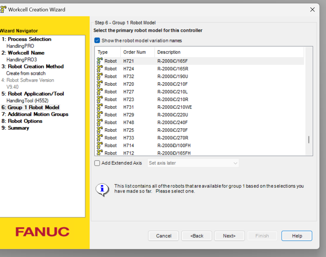
The next step is to configure the robot to be used in the application.
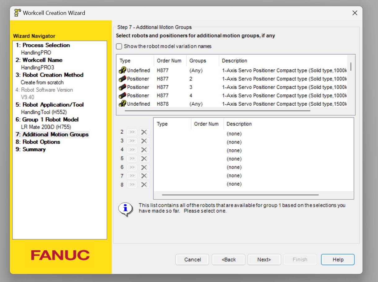
Set if there is an external axis.
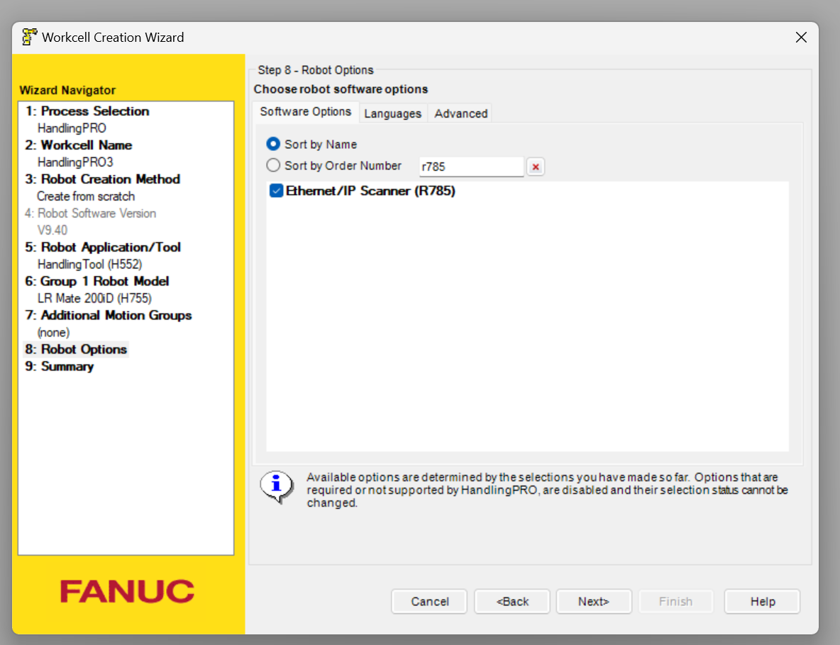
The next step is to set the robot Options.
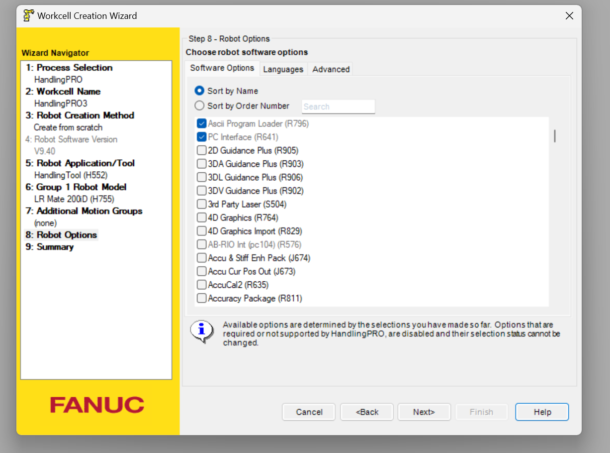
Since we will use r785 in this article, please search for r785 and put in Check.
Finally, check the Configuration and generate a new workcell with Finished.
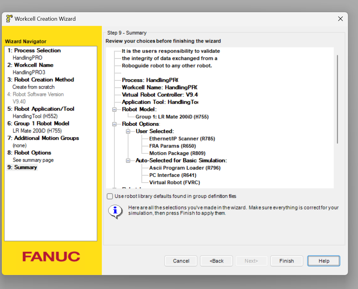
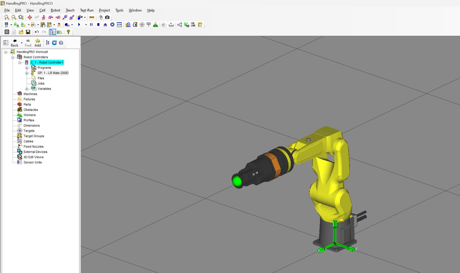
Done!
Start Teach Pendant
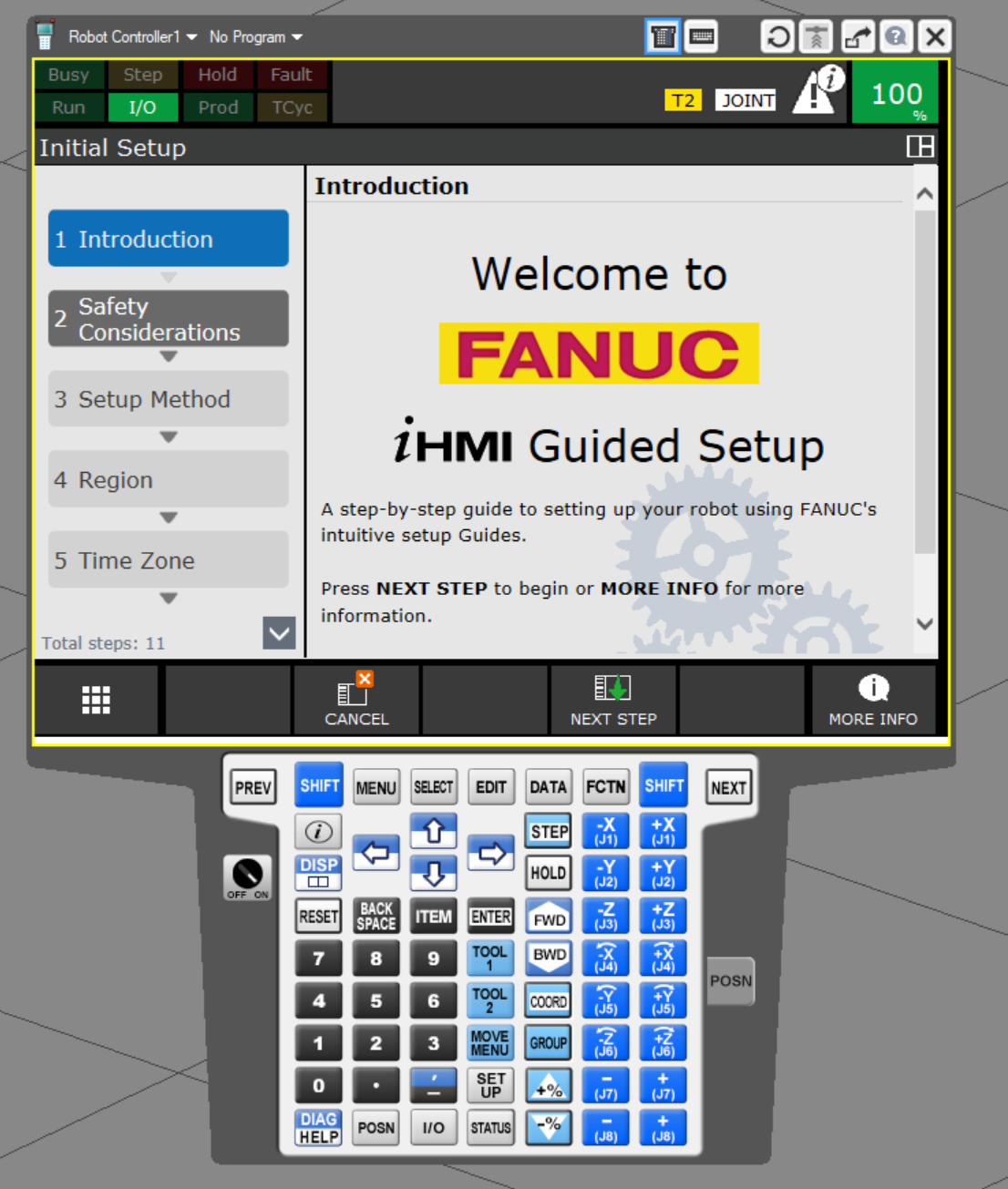
Start Teach Pendant to configure Ethernet/IP and other settings.
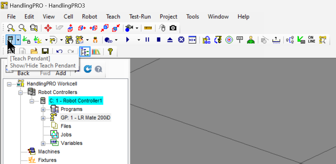
Done!Teach Pendant has been activated.
Host Comm
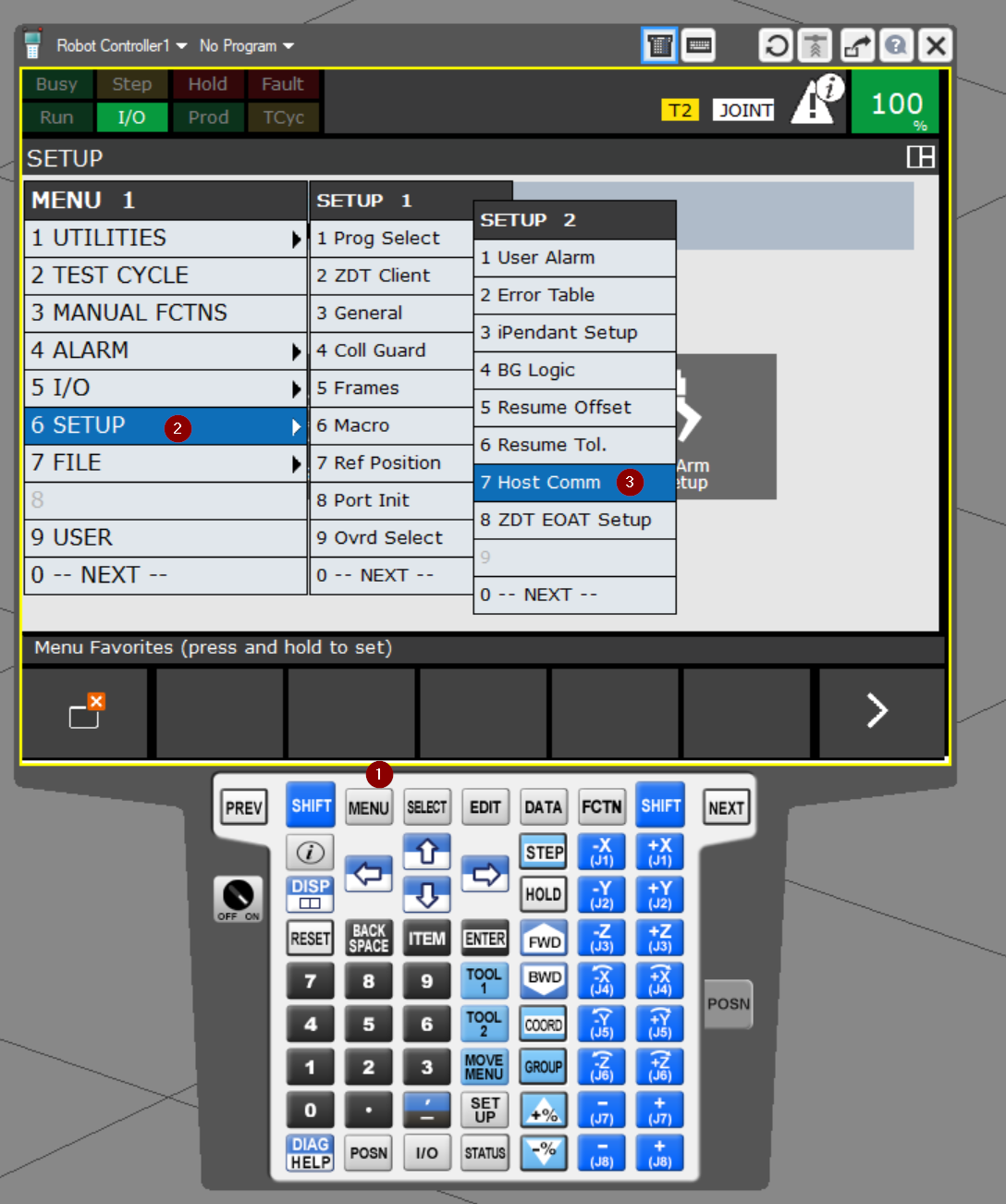
Now set the Host Comm. In other words,It is an operation to set the IP address of the Robot Controller.Click on the Menu button>6 SETUP>SETUP 2>7 Host Comm.
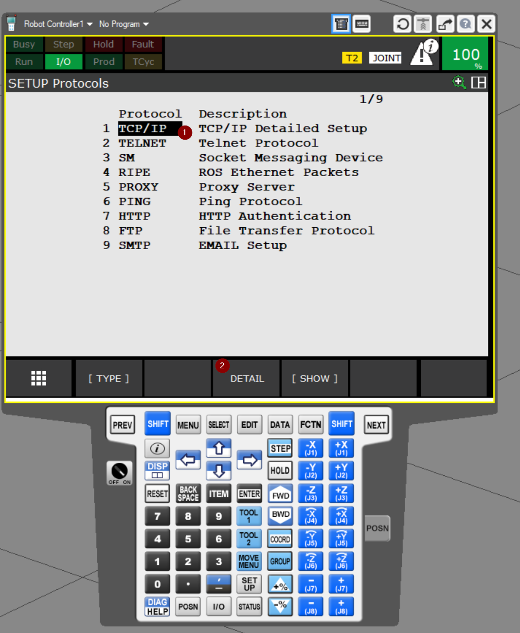
The Host Comm settings screen is now displayed.
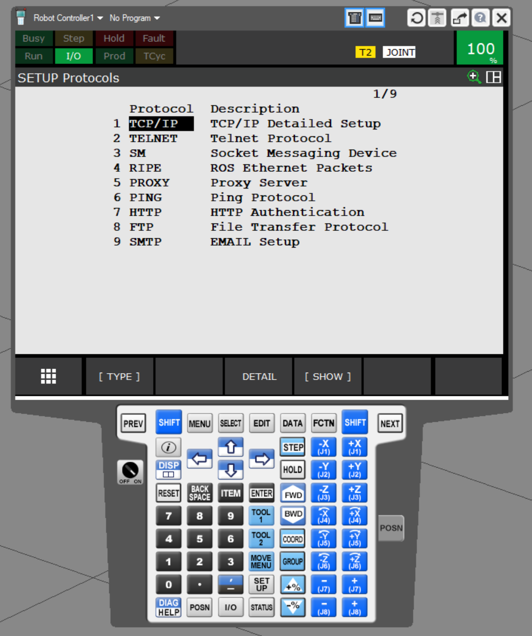
Select TCP/IP Protocol and click >DETAIL.
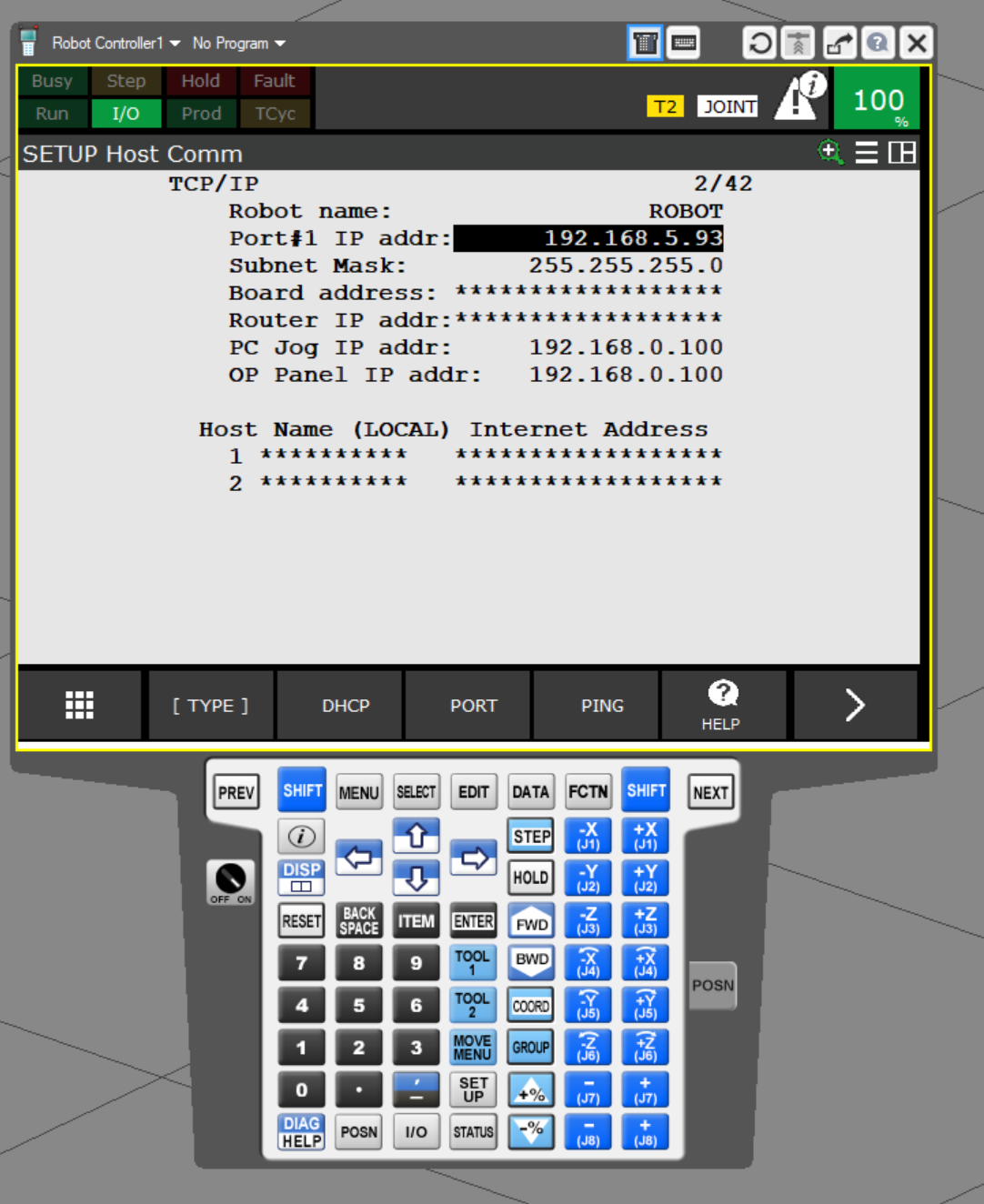
The TCP/IP configuration screen appears.
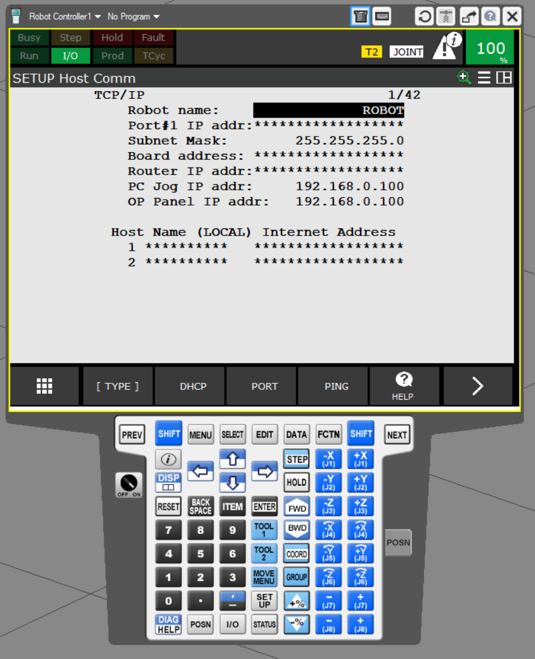
Port#1 IP addr is the IP address setting for Port 1 of Robot Controller.
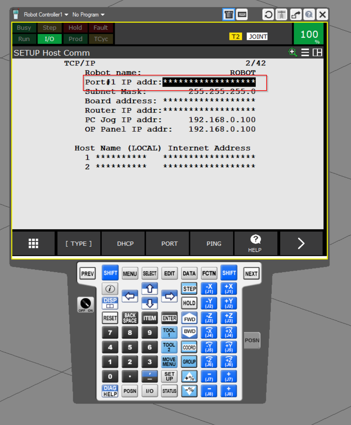
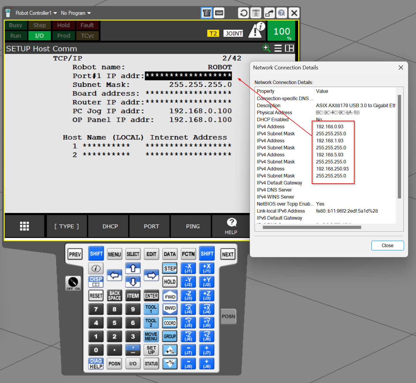
Since we are now using ROBOGUIDE, the IP should be set according to the network Adapter on the PC.
Click Port#1 IP addr to enter from the Keyboard.
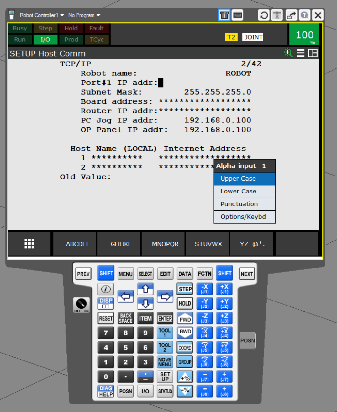
Done!
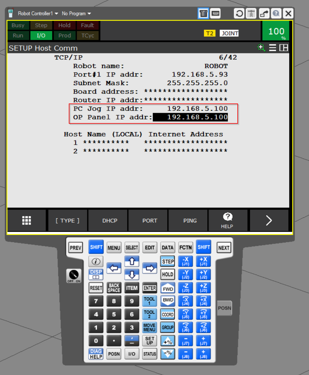
Next, let’s configure PC Jog IP addr and OP Panel IP addr.
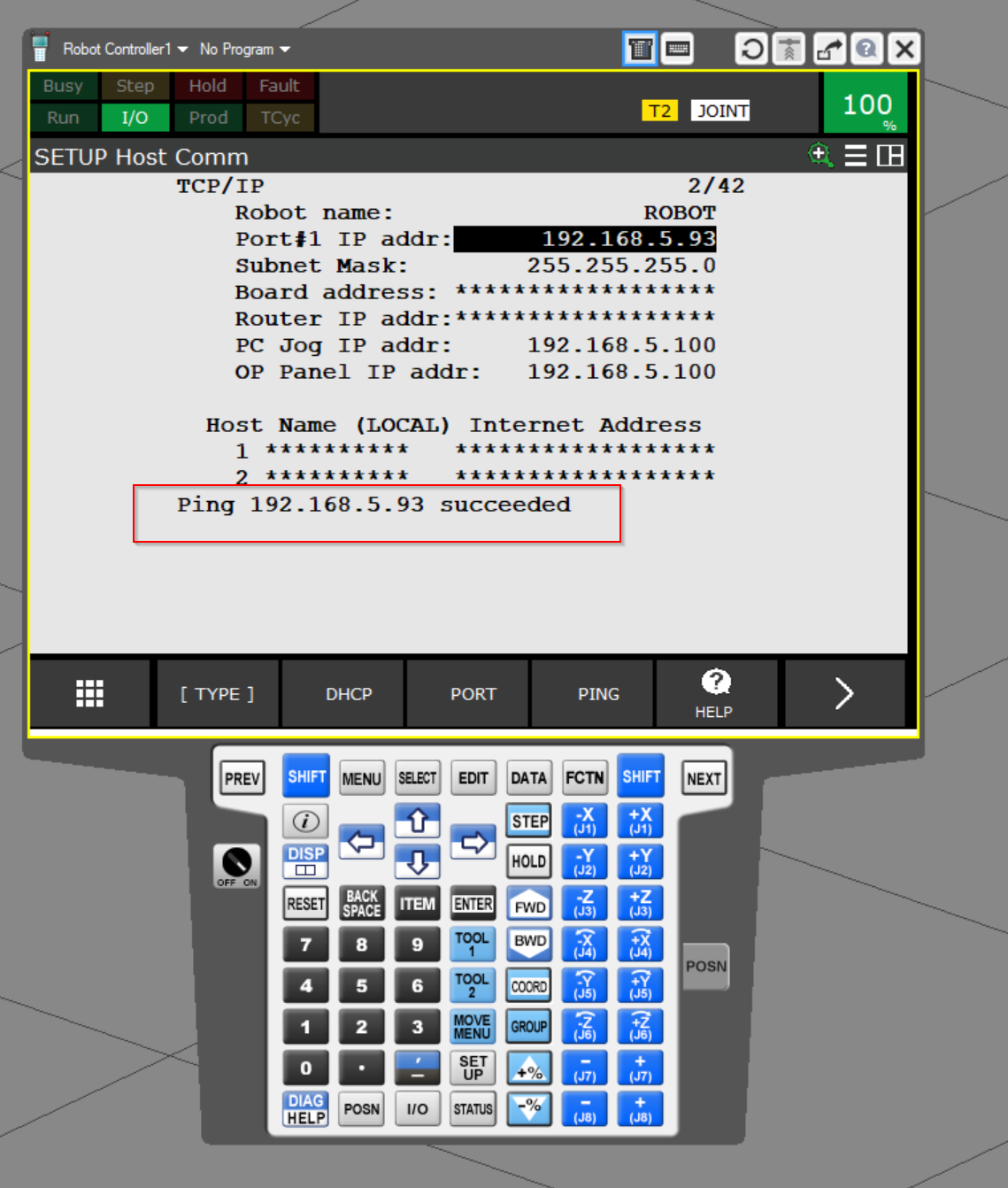
PING TEST
With Port#1 IP addr selected, click the PING button to test the connection.
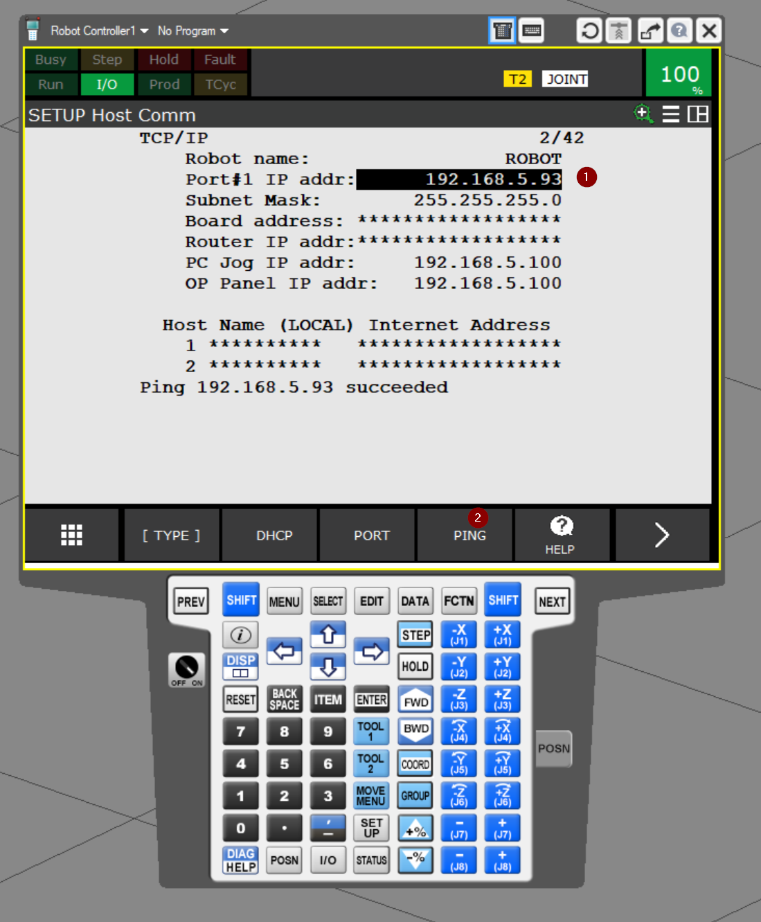
I got a Succeeded message, so the Host Comm setup is Ok.
Ethernet/IP Scanner
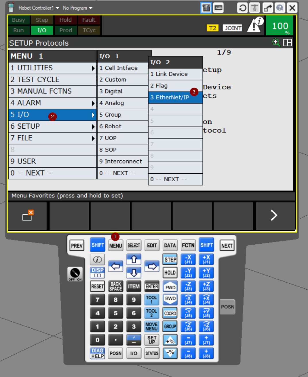
Next, open 5 I/O>I/O 2>3 Etherent/IP to configure the Ethernet/IP Scanner.
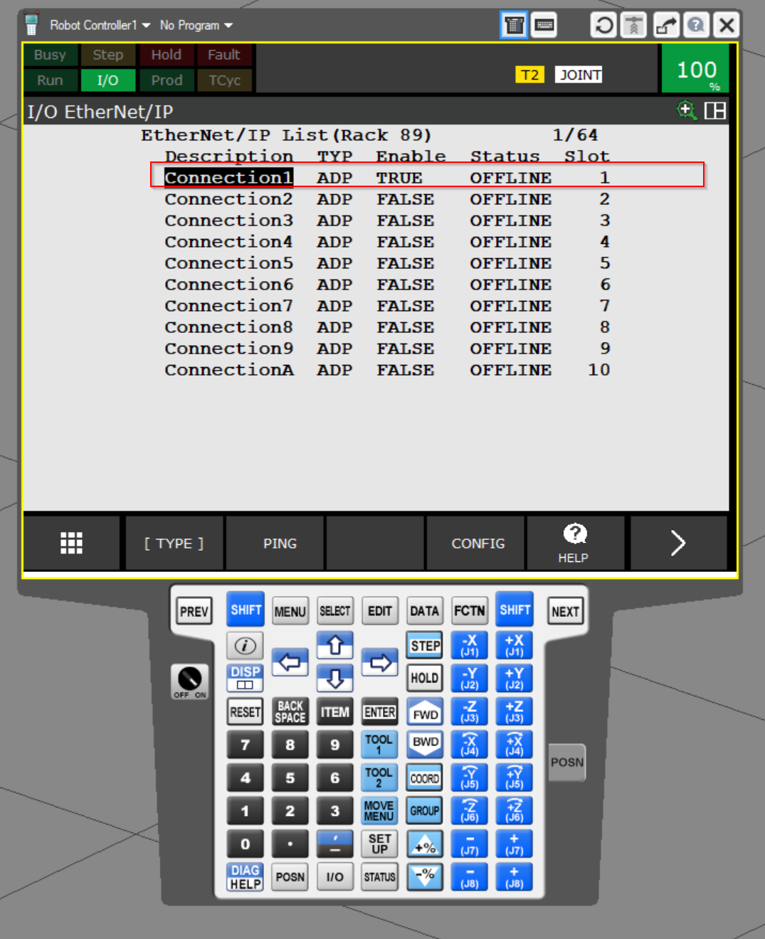
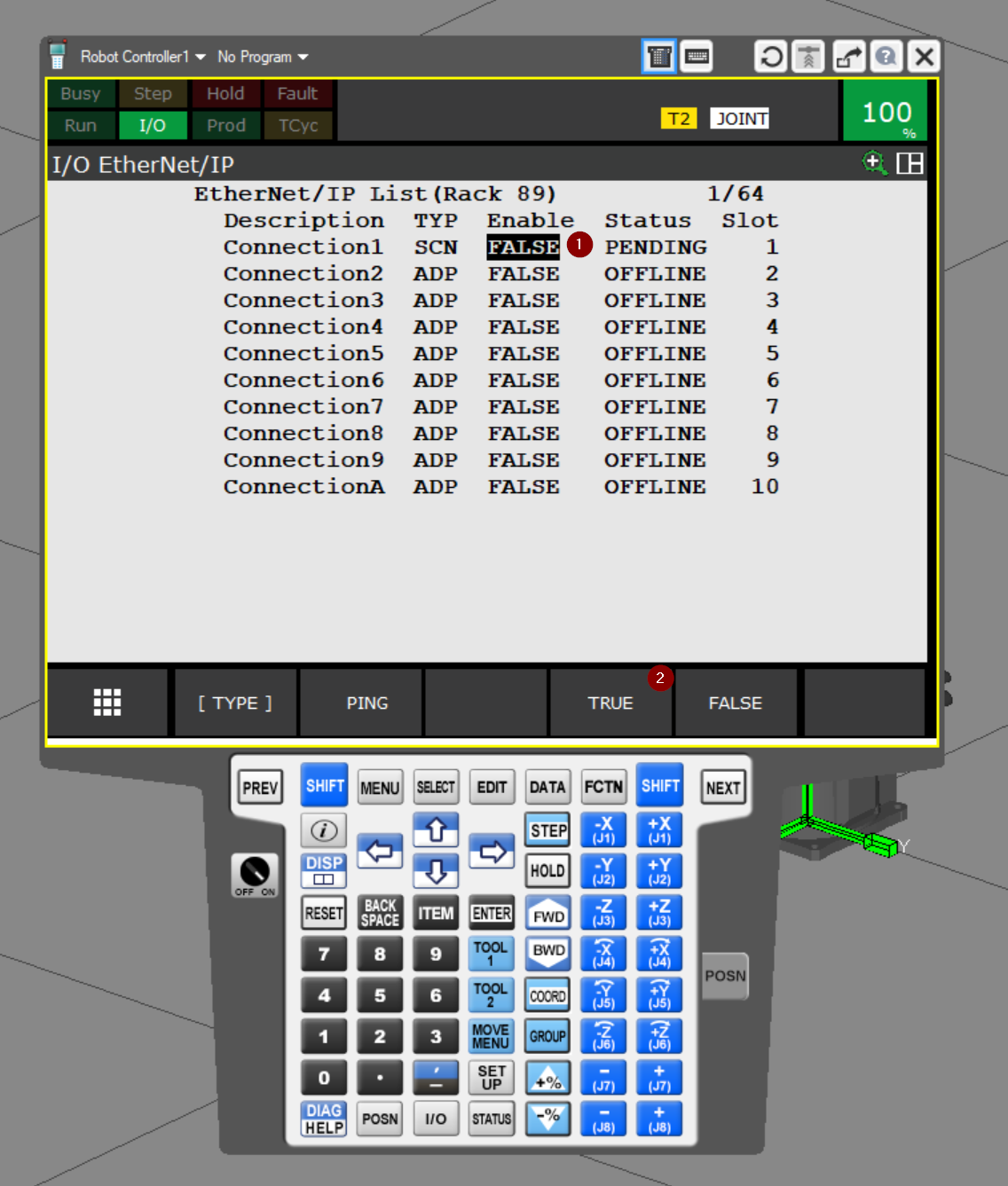
The I/O Ethernet/IP screen appears.
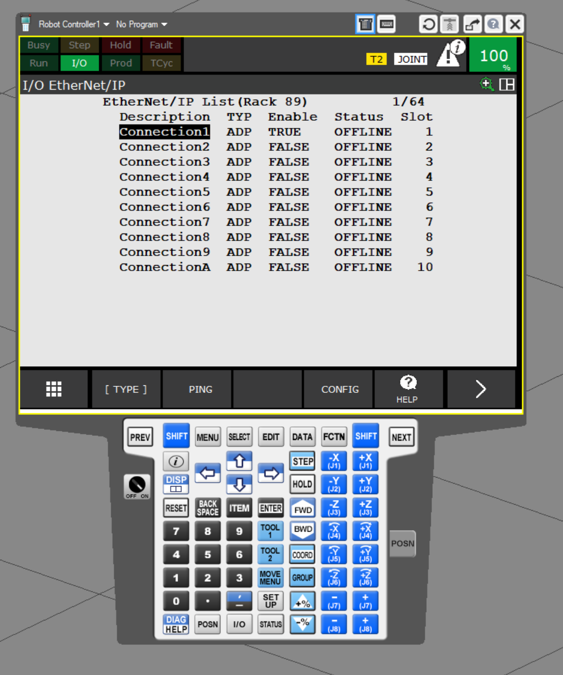
Connection1 will be used for this project.
Change to SCN
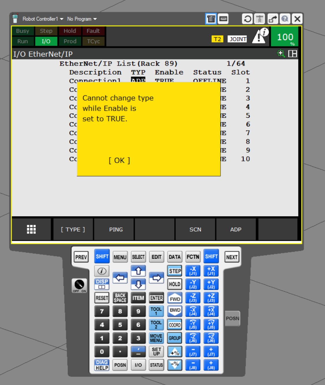
Select TYP and click the >SCN button.
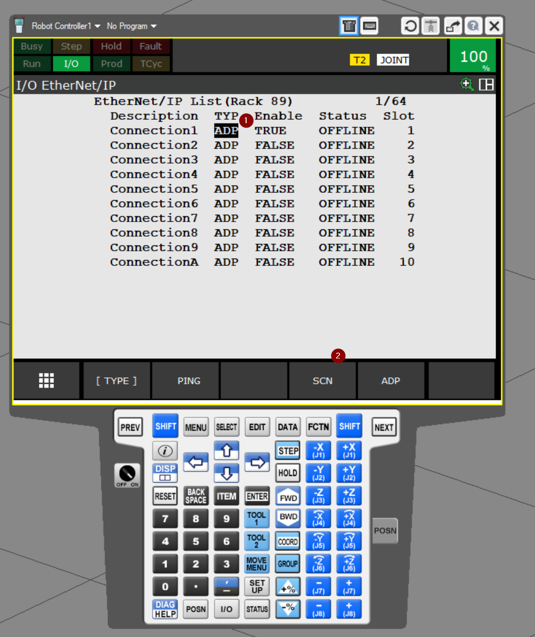
Since Connection1 is now Enabled, ROBOGUIDE has refused to change the TYP settings.
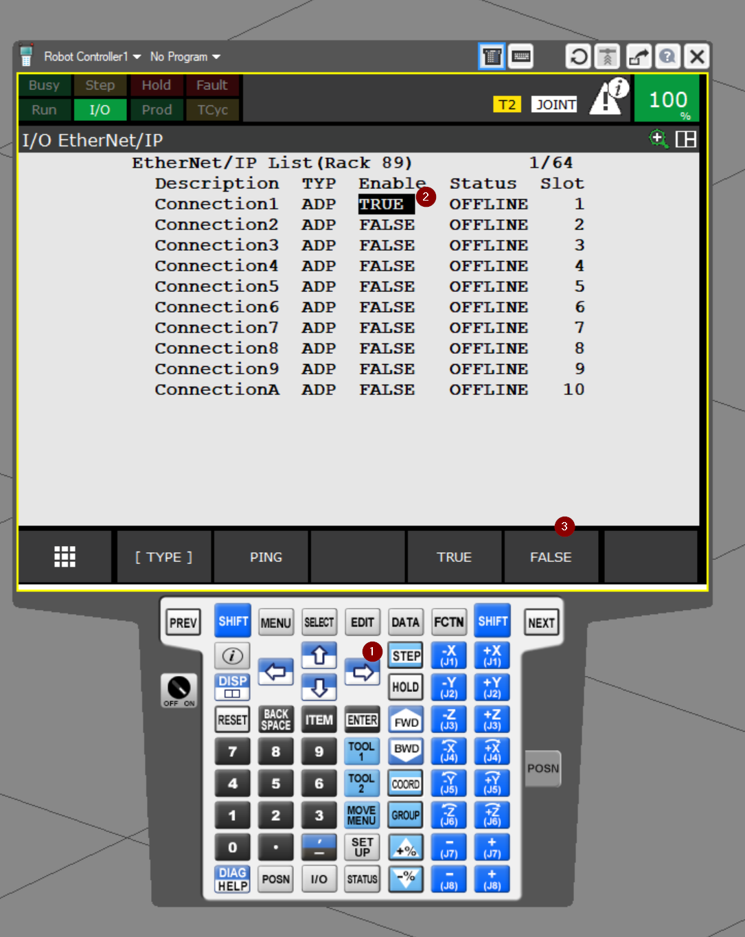
Disable the Function
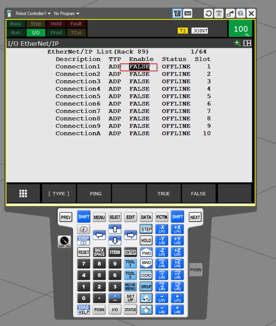
Go to the Enable column and click the FALSE button to disable the function of Connection1.
Done!
Select TYP once more and click SCN.
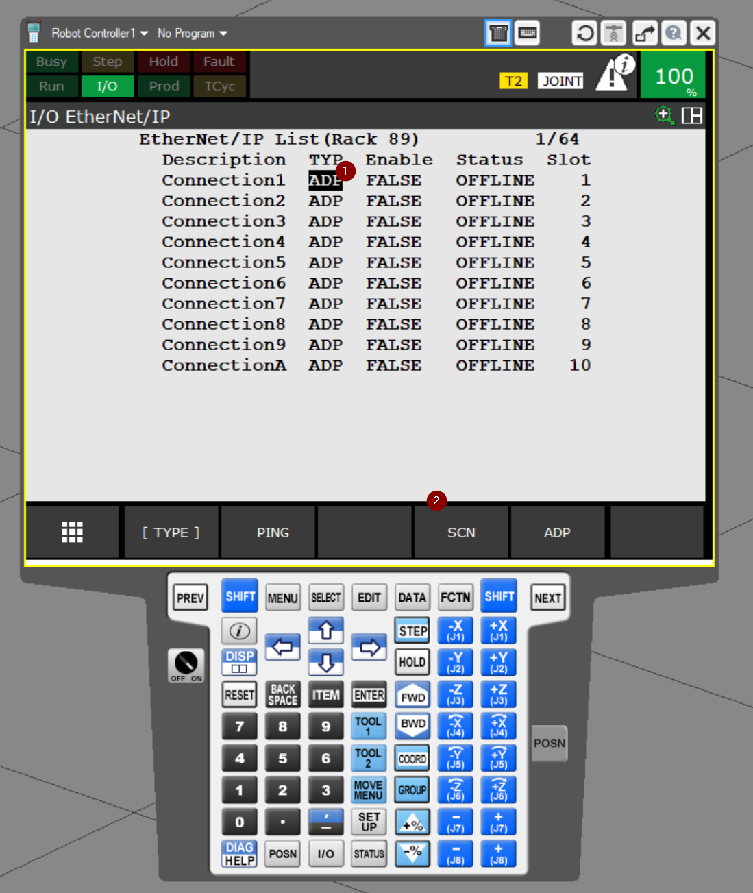
Do you want to change the connection type?Press Yes.
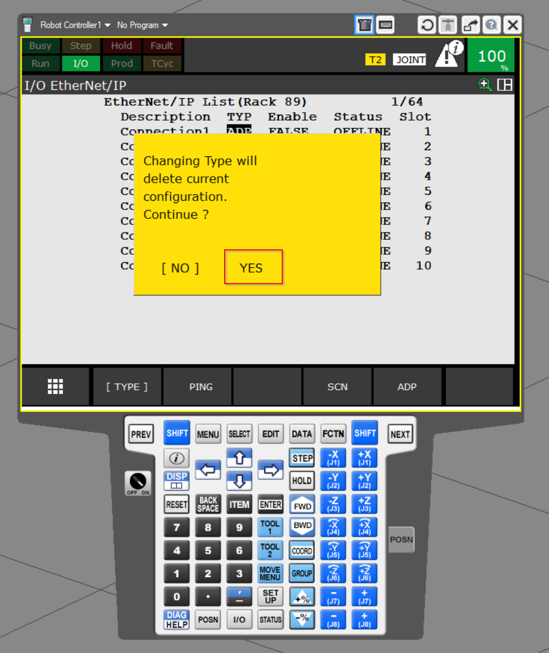
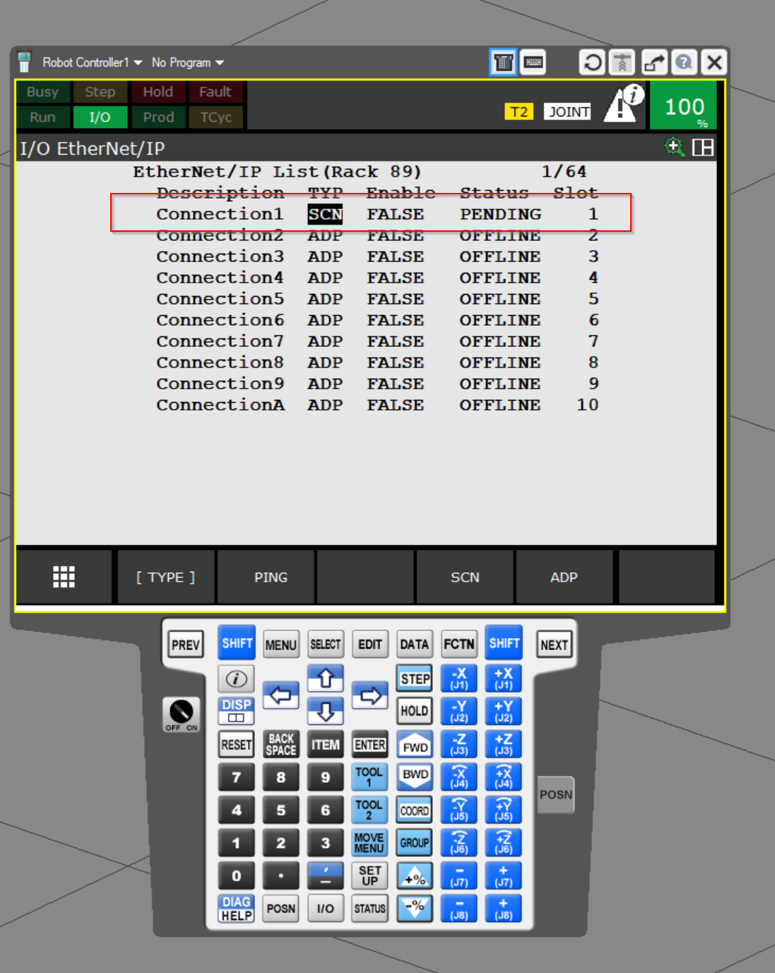
Done!Now Scanner’s Status has changed to PENDING.
CONFIG
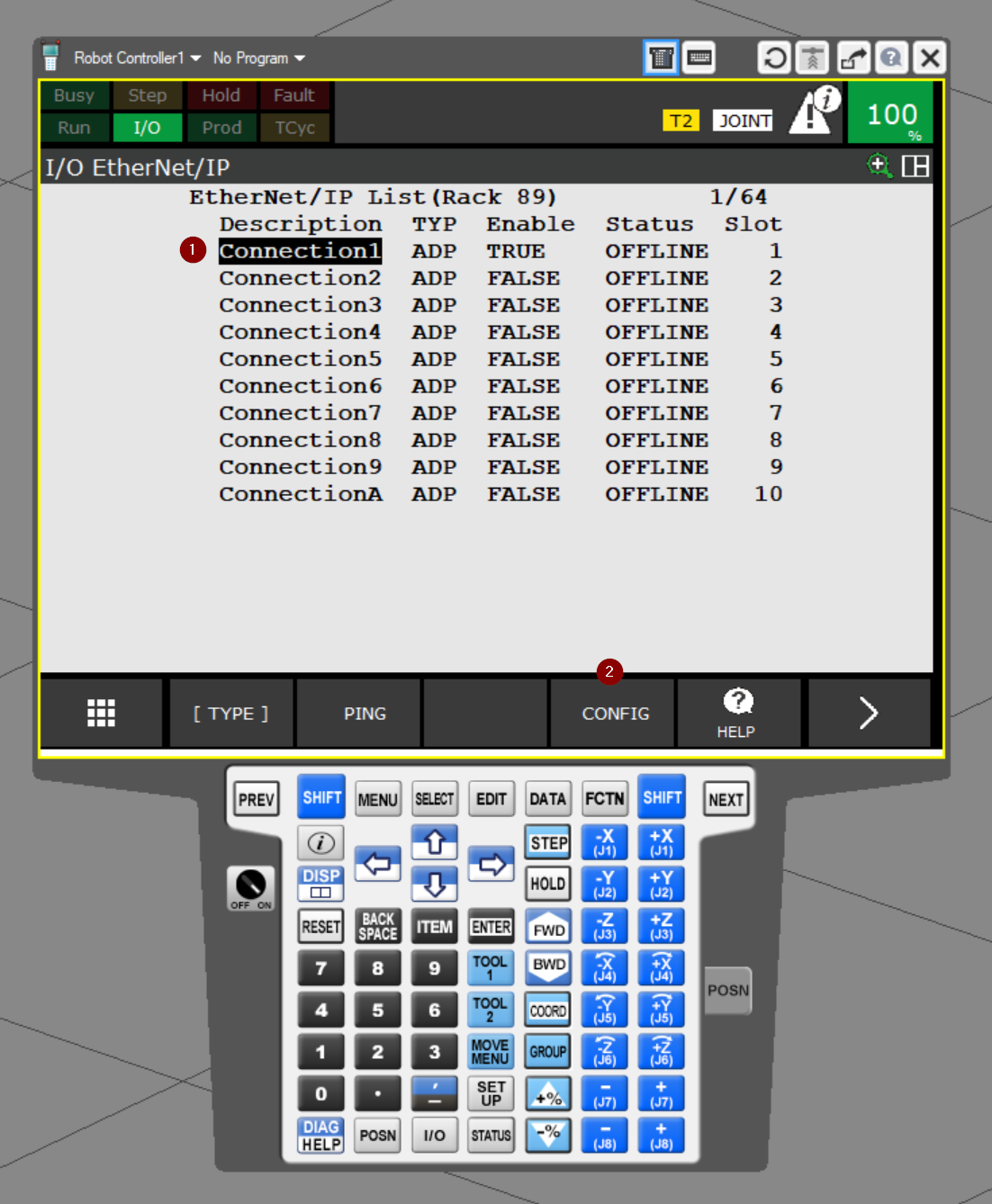
Next, to change the Configuration of Connection1, select Connection1 and click the >CONFIG button.
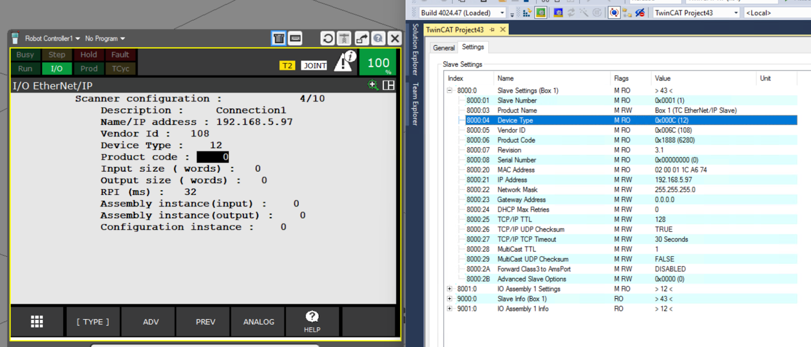
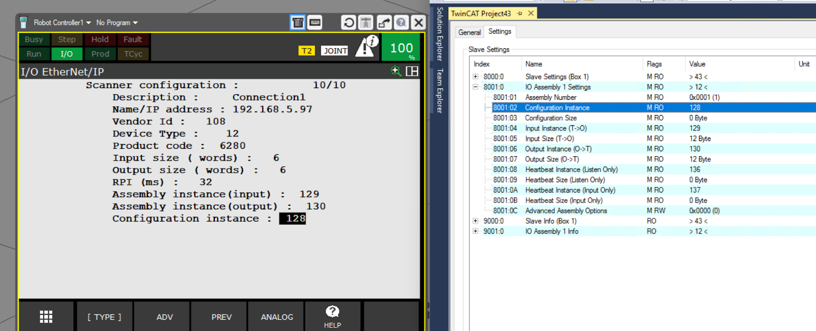
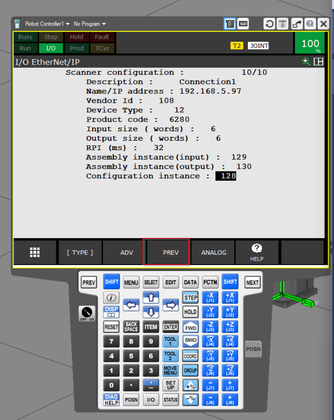
This is the Scanner Configuration setting screen. Although the name is a little complicated, this screen is used to configure the Ethernet/IP Adapter to be connected to the Scanner launched in ROBOGUIDE.
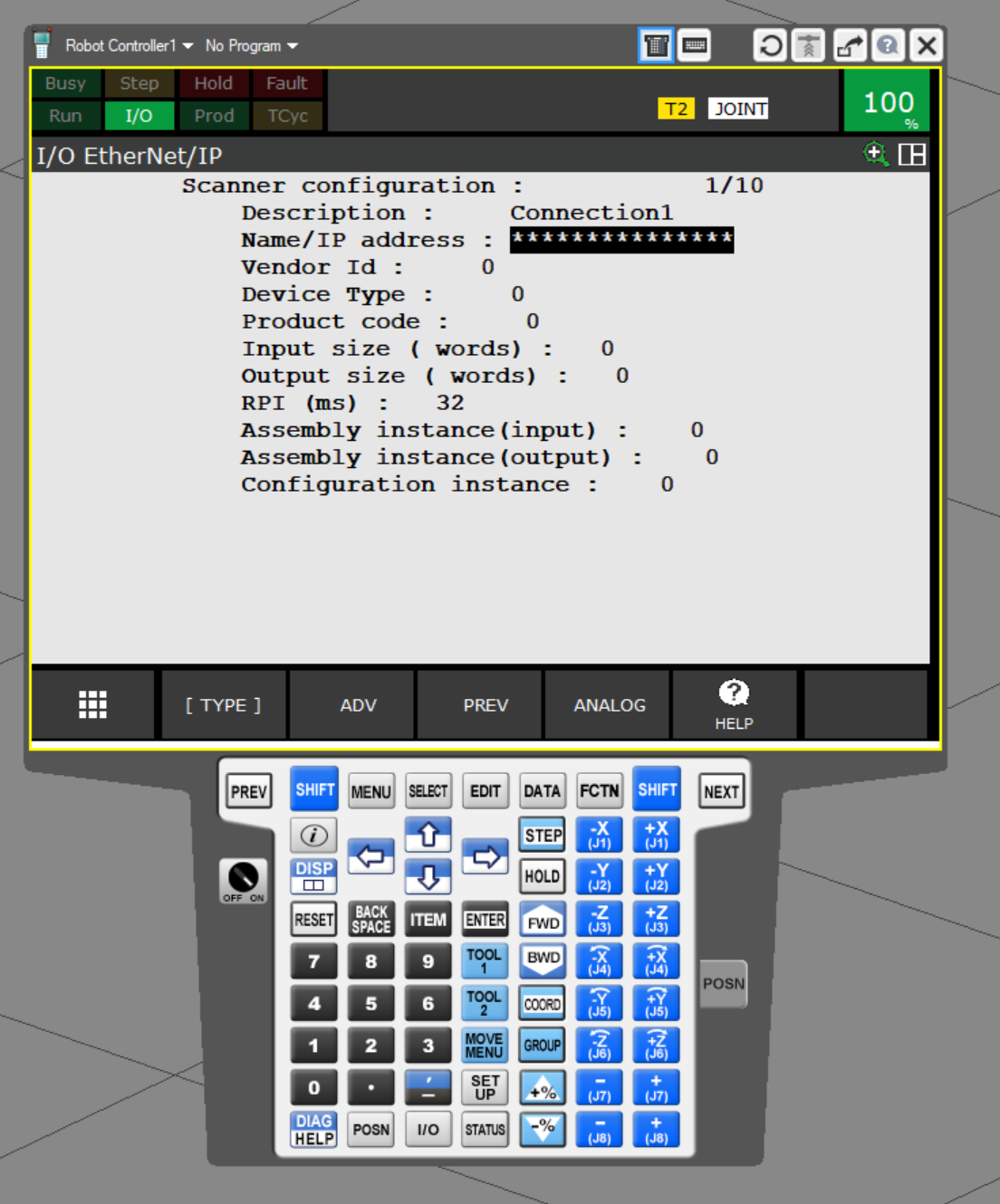
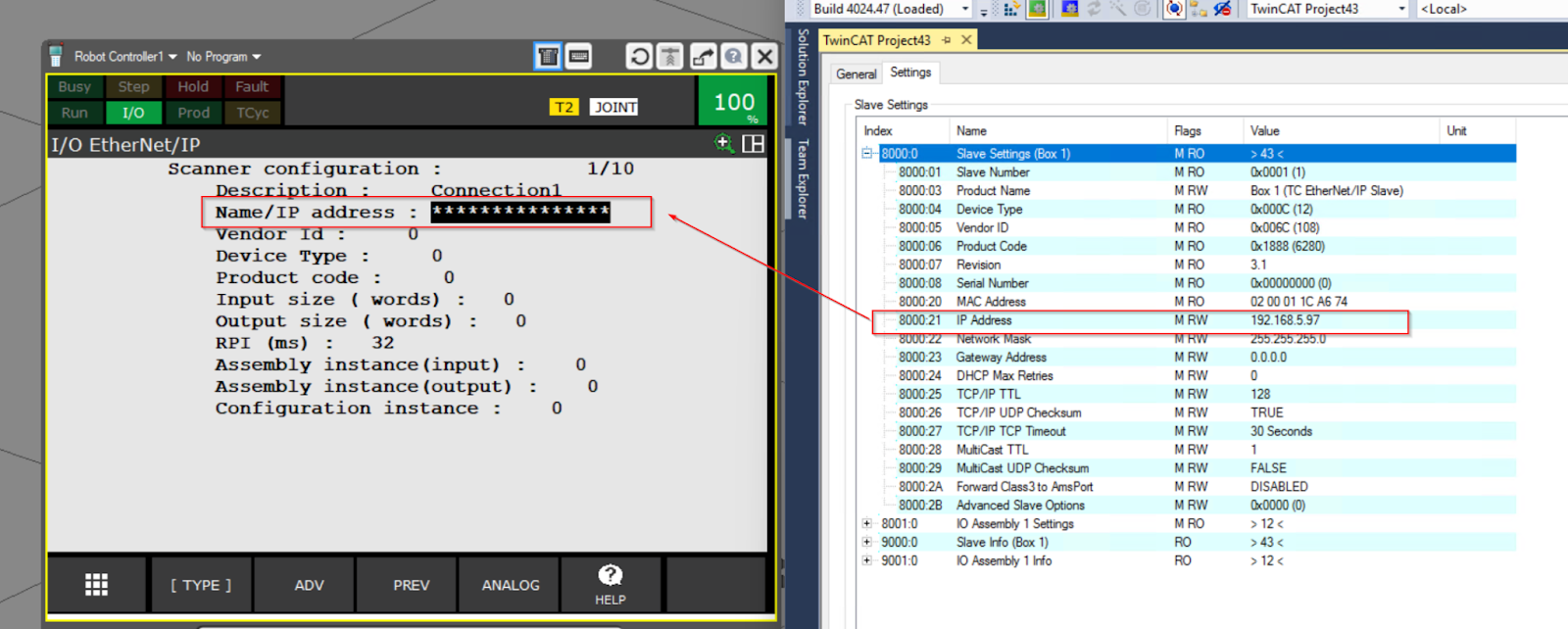
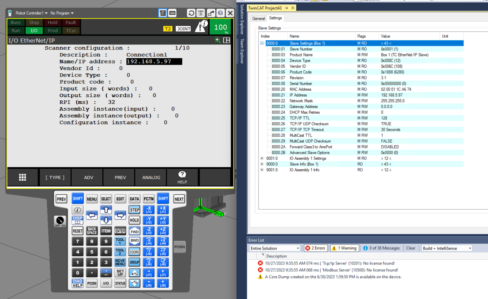
Name/IP address
Name/IP address is the IP address setting field of the Ethernet/IP Adapter and corresponds to 8000.21 in TwinCAT.
Done!
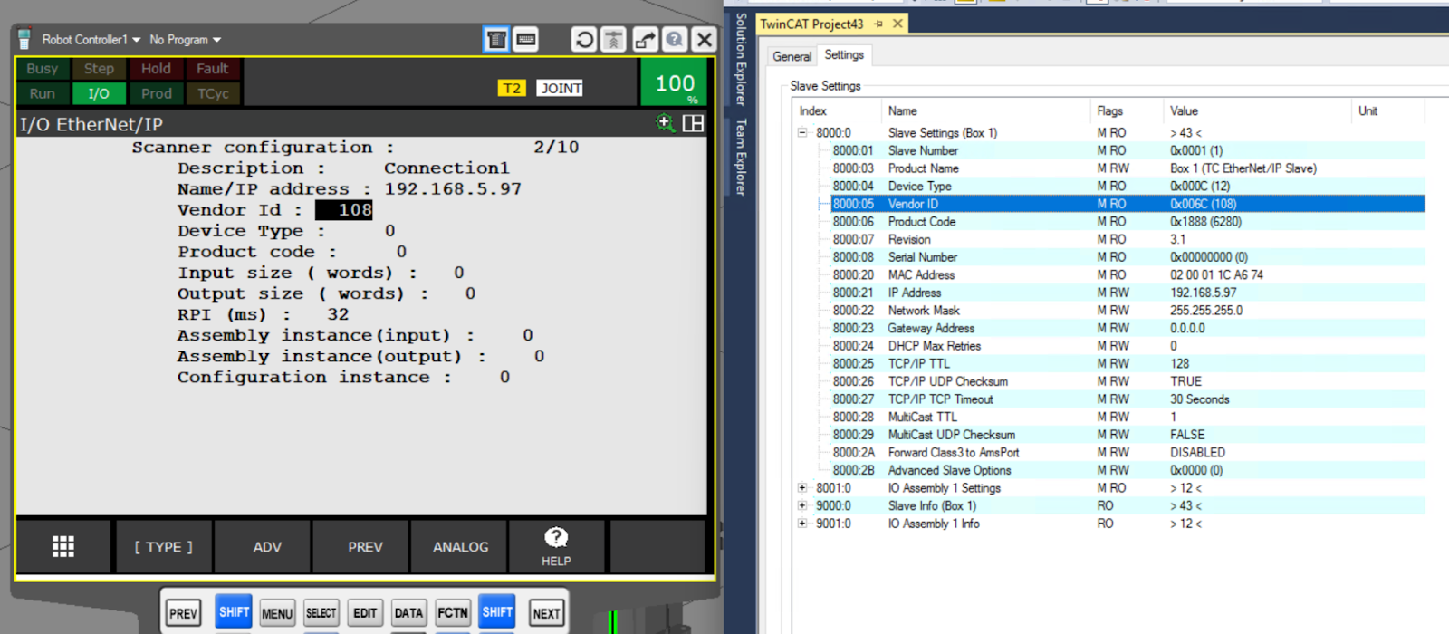
Vendor Id
Vendor Id is the Vendor Id setting item for the Ethernet/IP Adapter and corresponds to 8000.05 in TwinCAT.

Done!
Device Type
Device Type is the Device Type setting item for the Ethernet/IP Adapter and corresponds to 8000.04 in TwinCAT.
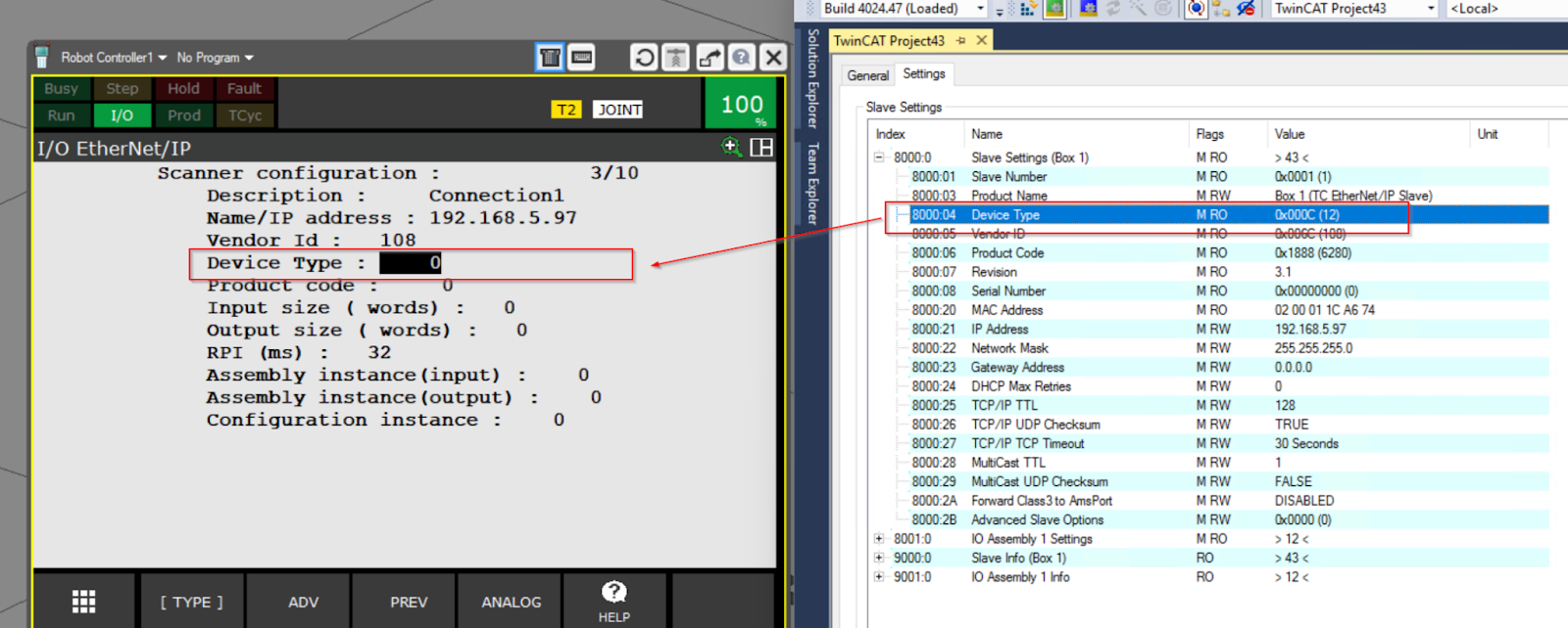
Done!
Product Code
Product Code is the Product Code setting for the Ethernet/IP Adapter and corresponds to 8000.06 in TwinCAT.
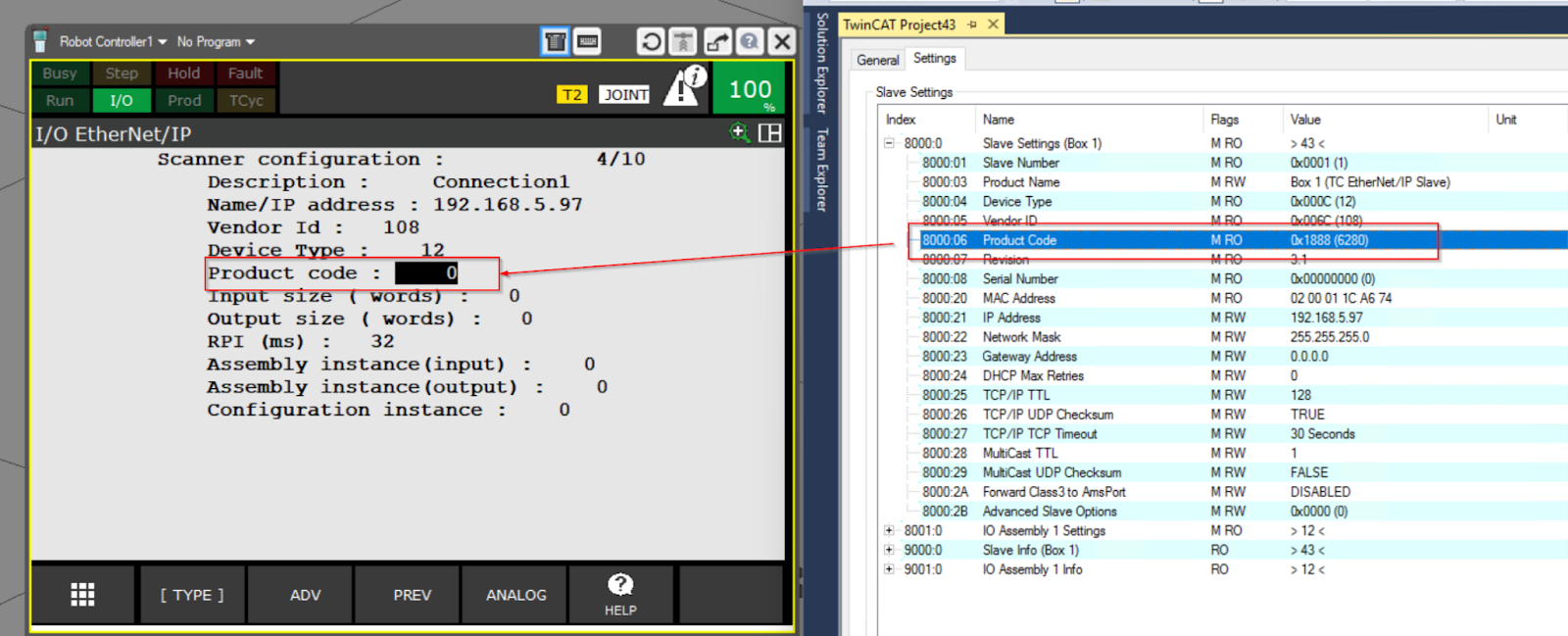
Done!

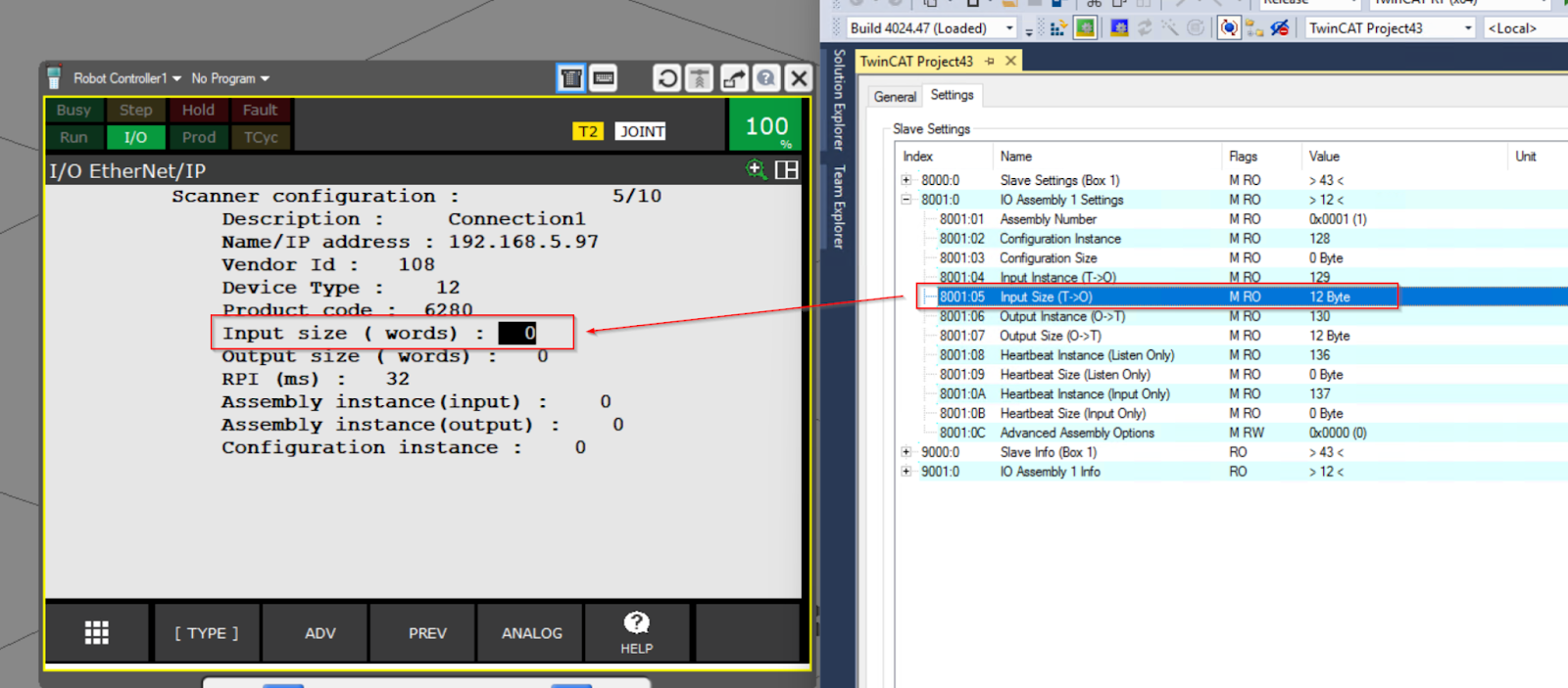
Input size(words)
Input size (words) is the input data size setting item for the Ethernet/IP Adapter and corresponds to 8001.05 in TwinCAT.
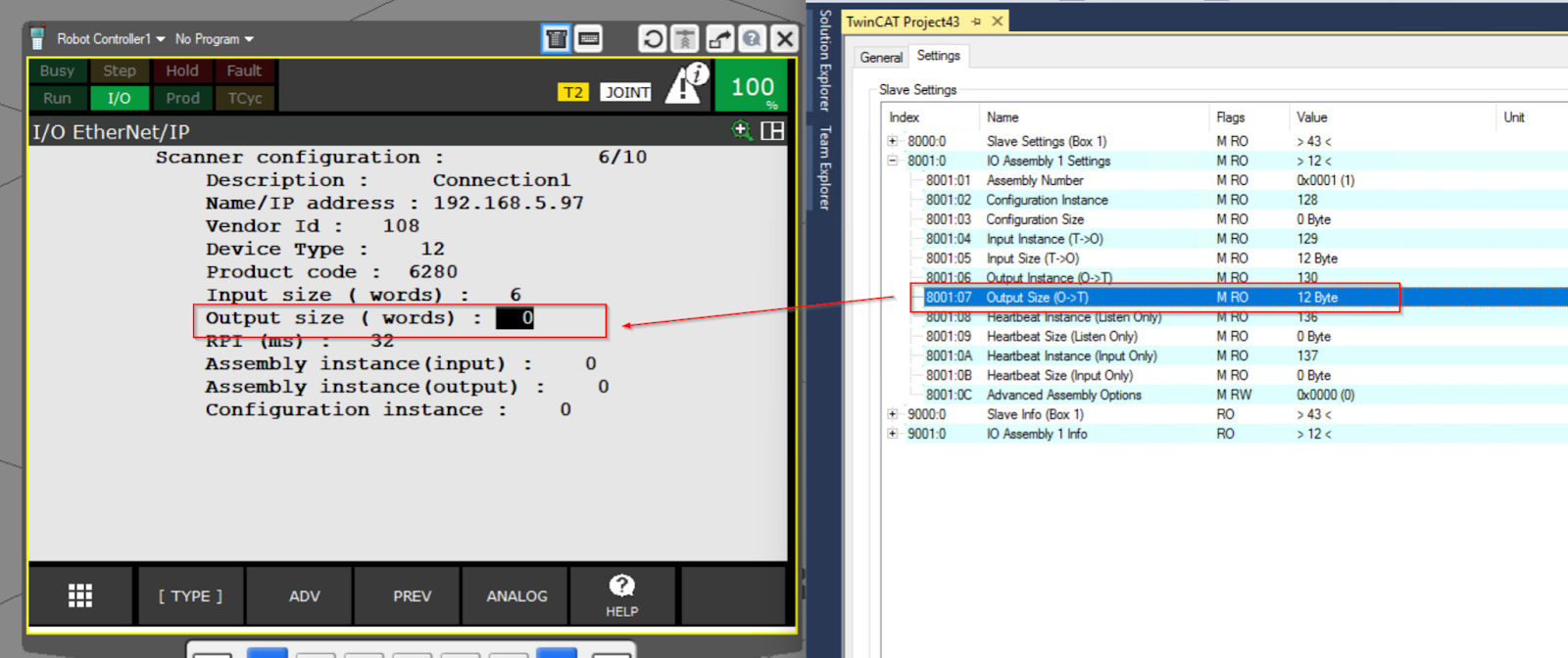
Output size(words)
Output size (words) is a setting item for the output data size of the Ethernet/IP Adapter and corresponds to 8001.07 in TwinCAT.
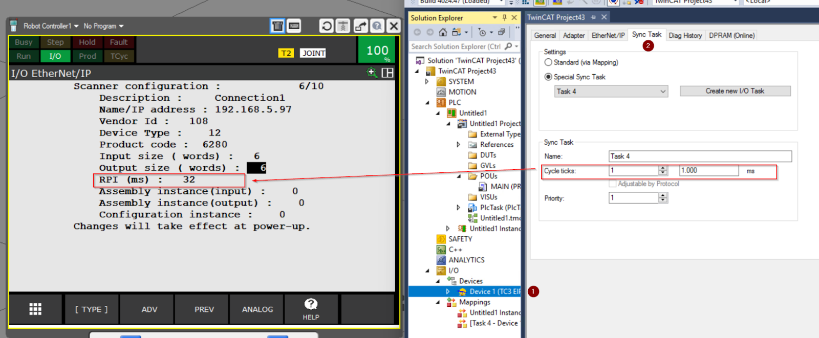
RPI(ms)
RPI(ms) is the update cycle of data exchange with the Ethernet/IP Adapter and should be set larger than the Cycle ticks set in the Sync Task of the Ethernet/IP Adapter in TwinCAT.
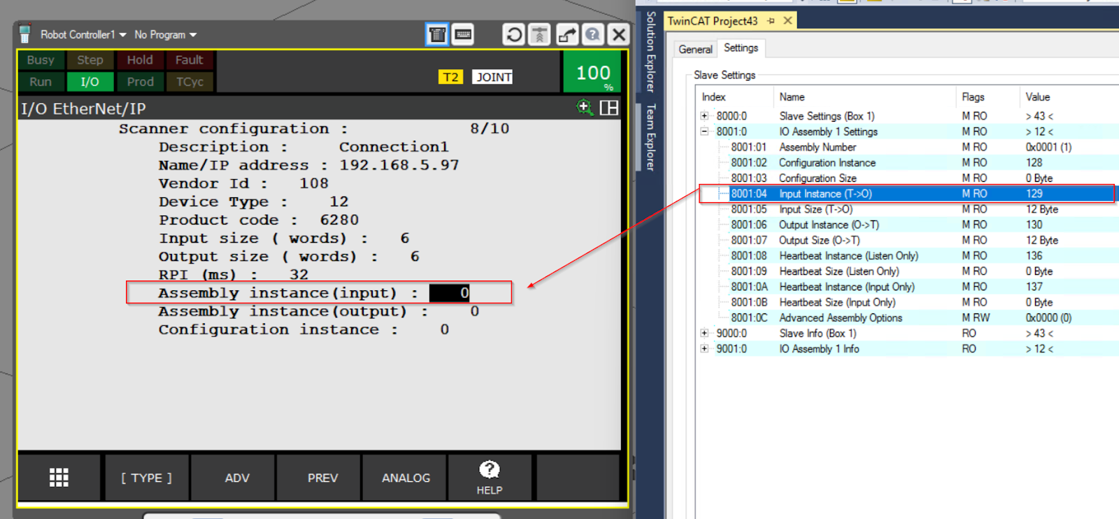
Assembly instance(input)
Assembly instance(input) is the input data instance number setting item for the Ethernet/IP Adapter and corresponds to 8001.04 in TwinCAT.
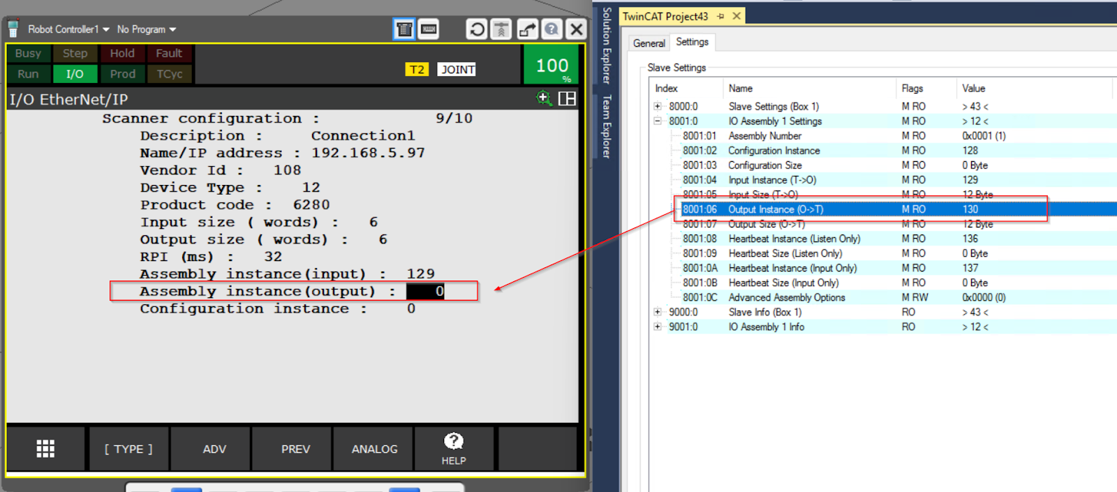
Assembly instance(output)
Assembly instance(output) is the Ethernet/IP Adapter output data instance number setting item and corresponds to 8001.06 in TwinCAT.
Configuration instance
Configuration instance is the Configuration data instance number setting item for the Ethernet/IP Adapter and corresponds to 8001.02 in TwinCAT.
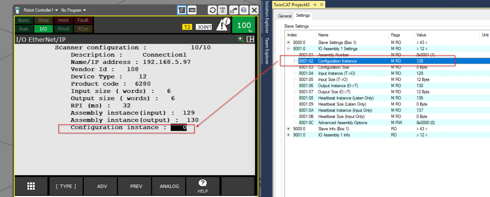
Done!
Result
Done!
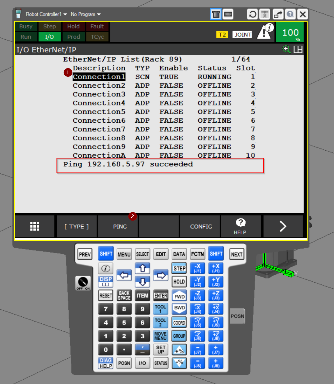
PING
To check the communication between the Beckhoff TwinCAT Ethernet/IP Adapter and ROBOGUIDE, select Connection1 and click >PING.
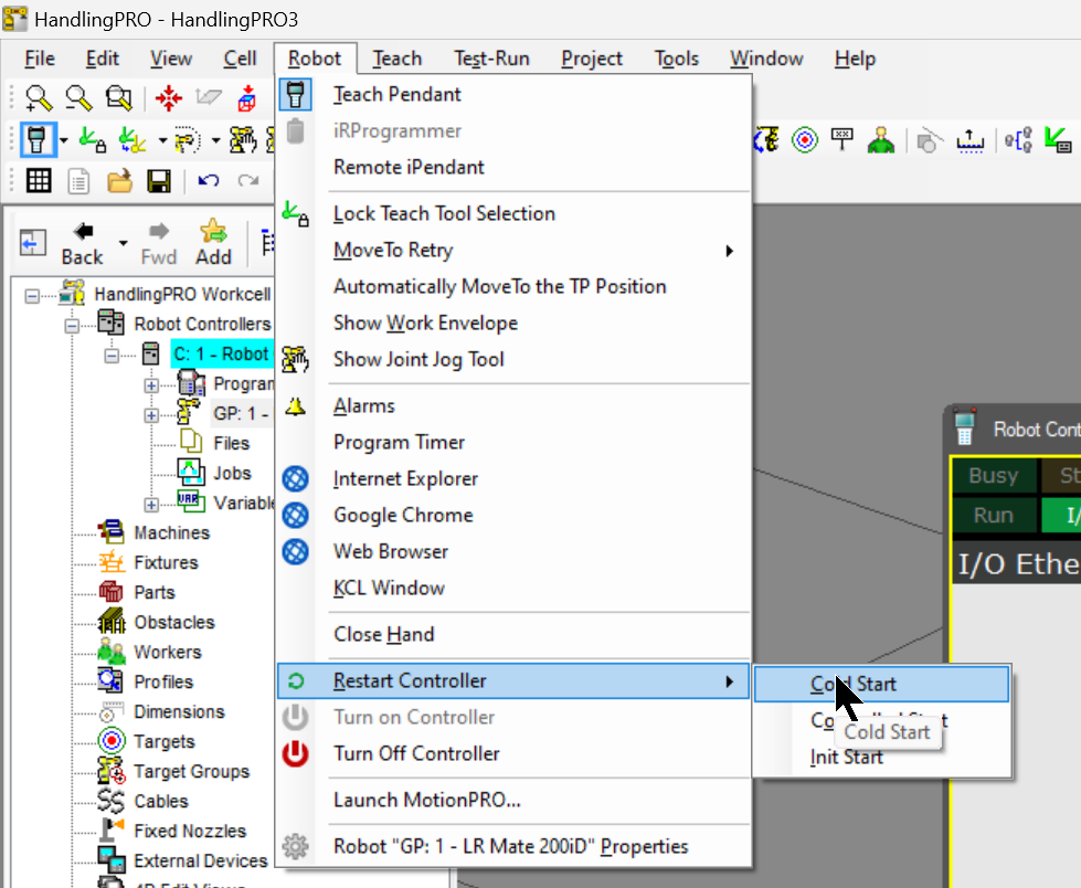
Reset the Controller
Once the Ethernet/IP Adapter connection settings are complete, reset the Robot Controller once with Robot>Restart Controller>Cold Start.
Enable Scanner
To Enable Ethernet/IP, select the Enable setting in Connection1 and set it to >True.
Enable Remote Operation
Next you need to enable Remote Control Options for Robot Controller, click 0 –NEXT –.
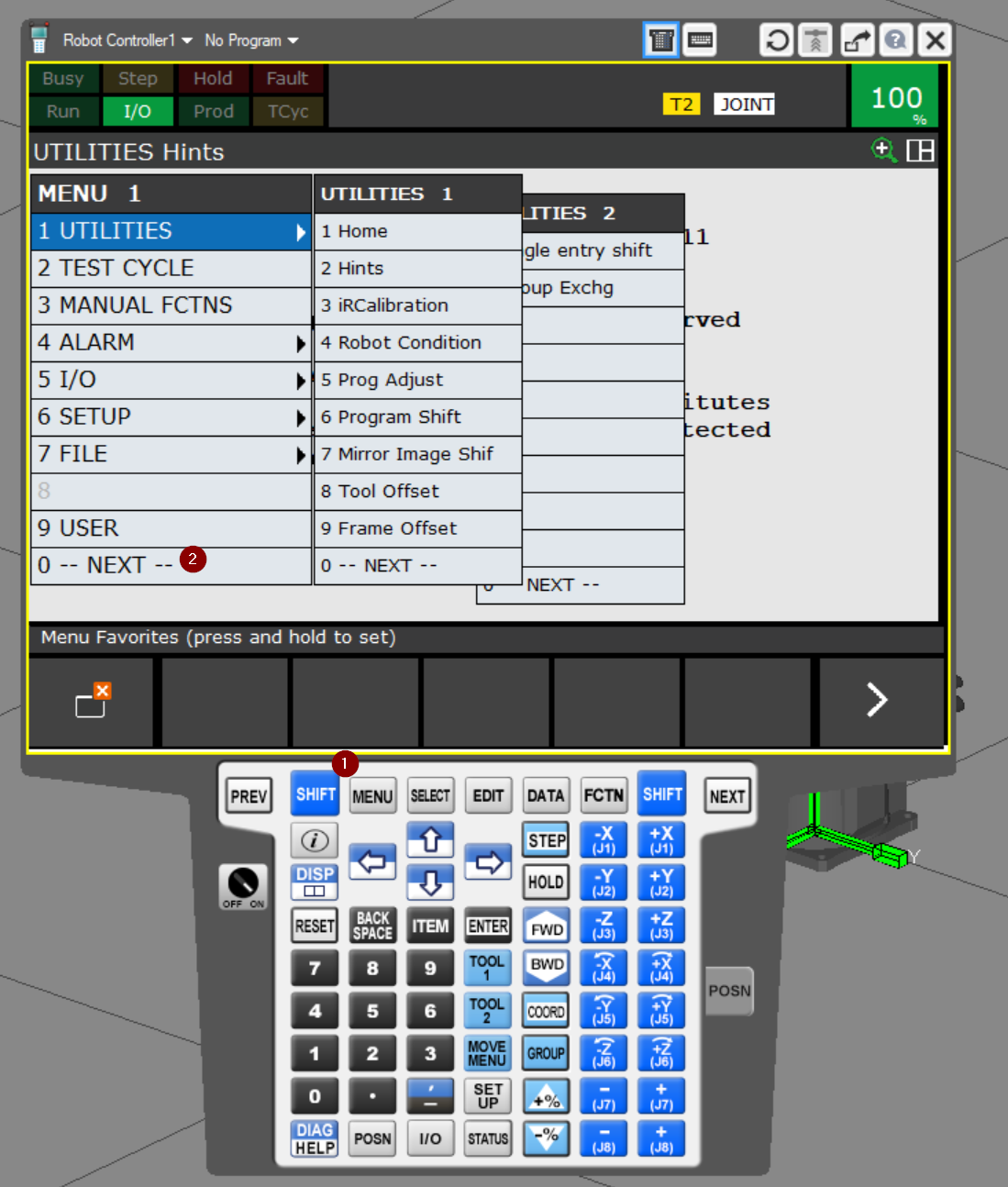
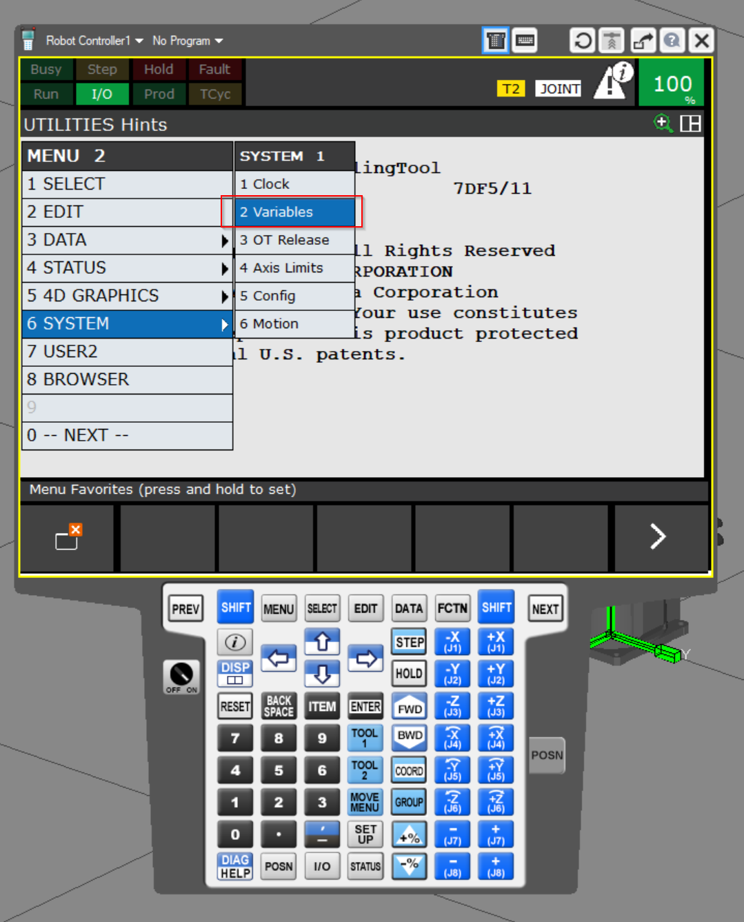
Open MENU2>6 SYSTEM>2 Variables.
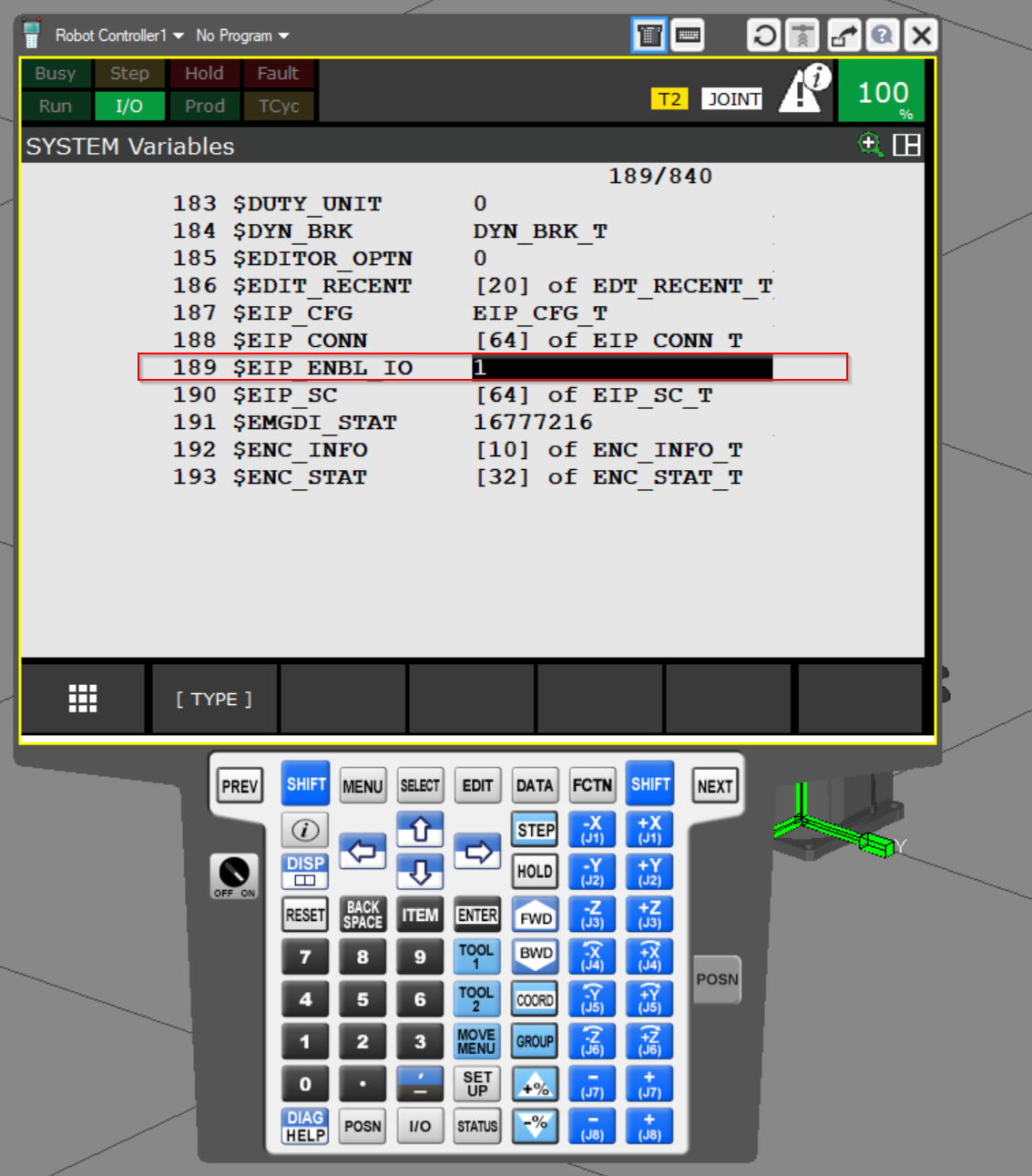
Set variable 189 Set $EIP_ENBL_IO to 1.
Result
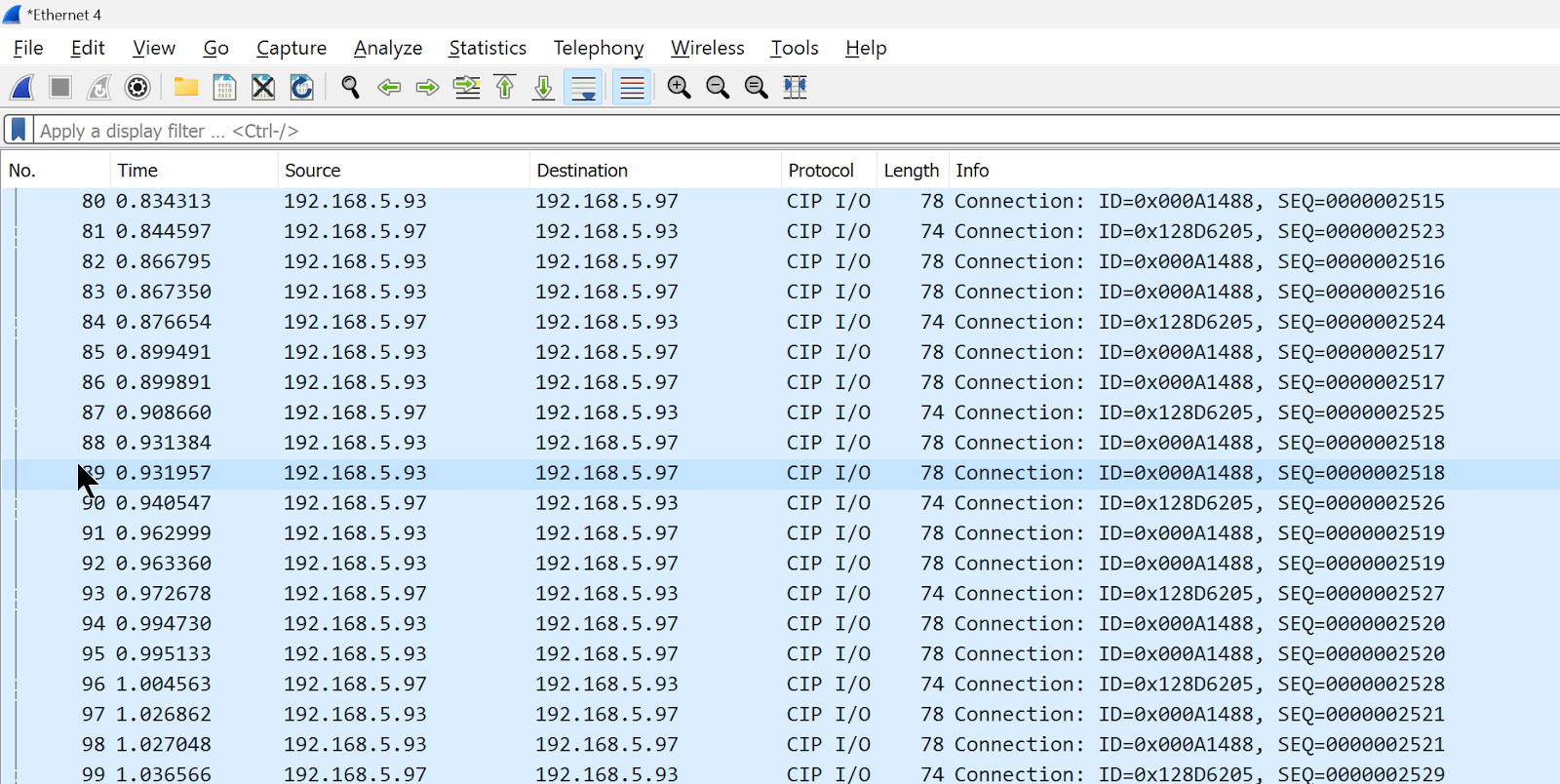
You can see the Packets from Wireshark for ROBOGUIDE and TwinCAT CIP I/O! So communication was established.
Implementation2
Next, we will check the IO data from the FANUC ROBOGUIDE side.
FANUC Side
Configure IO
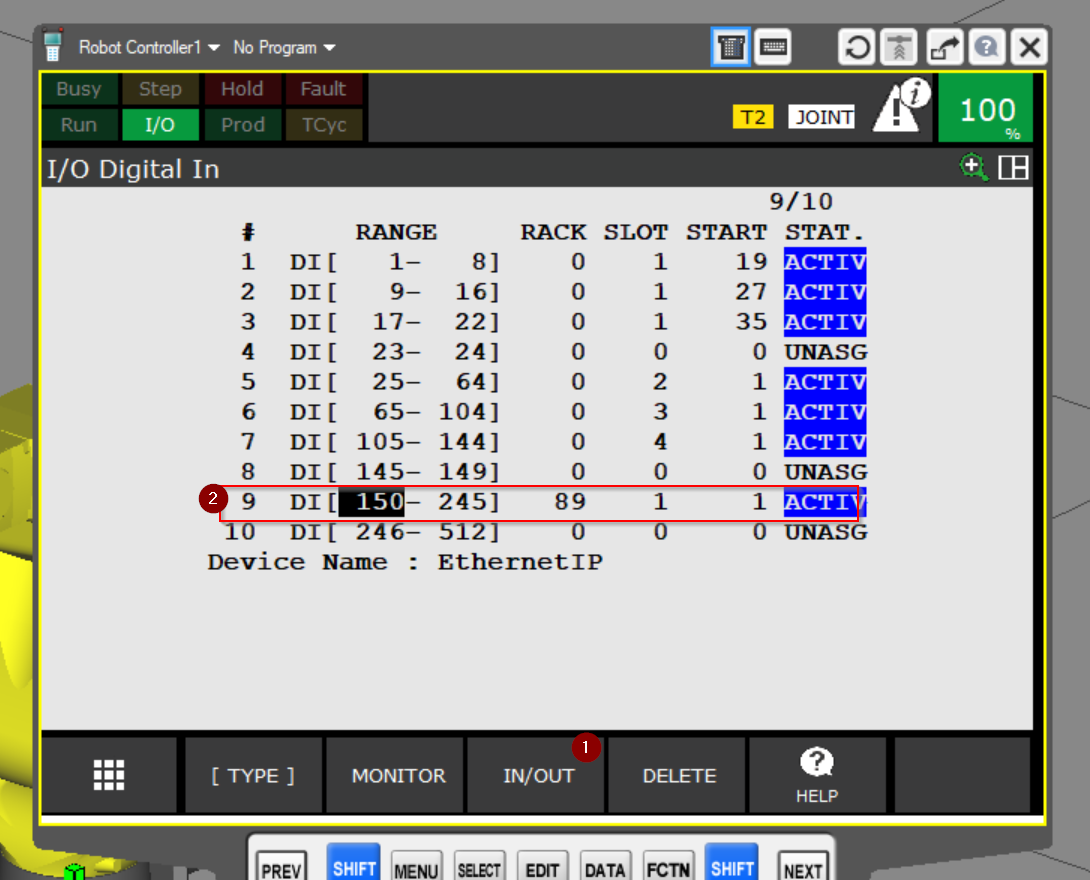
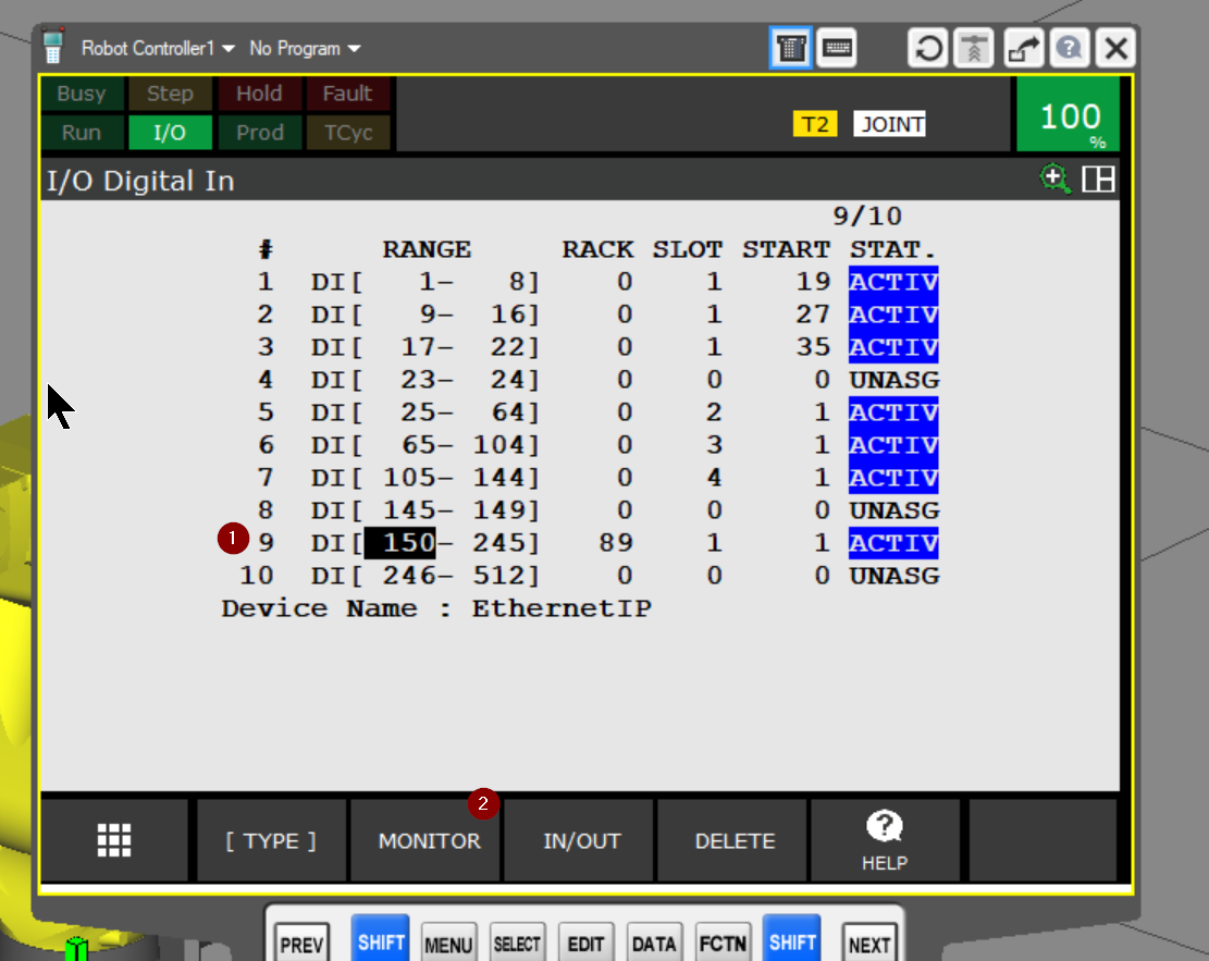
Open the IO Configuration screen and click on the IN/OUT button.
It may be a little confusing, but RACK89 is the Ethernet/IP communication RACK, and SLOT1 indicates Connection1. Then START=1 takes data from Bit 0 and transfers it to DI numbers 150 to 245.
From 150 to 245 is exactly 6 Words, which corresponds to the data size of Beckhoff TwinCAT Ethernet/IP communication.
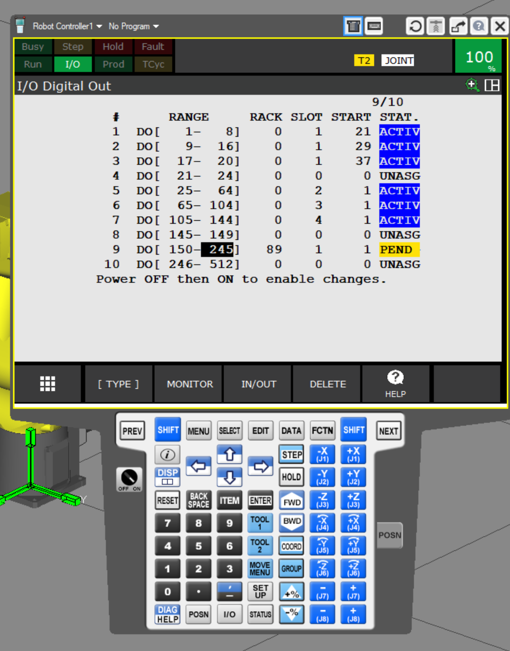
Set up the same for DOs.
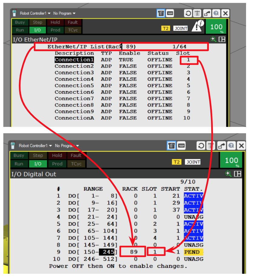
Here is the setting relationship between the I/O Digital and I/O Ethernet/Ip screens.
Result
Now, to check the DI data, select DI and click >MONITOR.
The status of each input can be checked from DI[150]; SIM=U is also a non-simulation state, and STATUS=OFF means that the corresponding DI number is currently OFF.

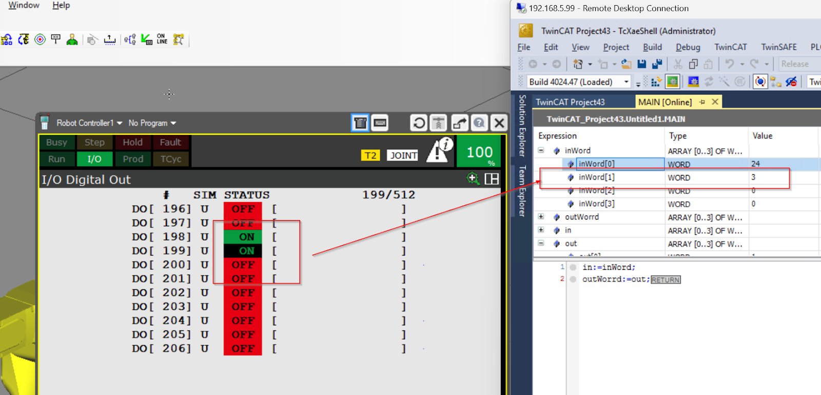
DO Word1
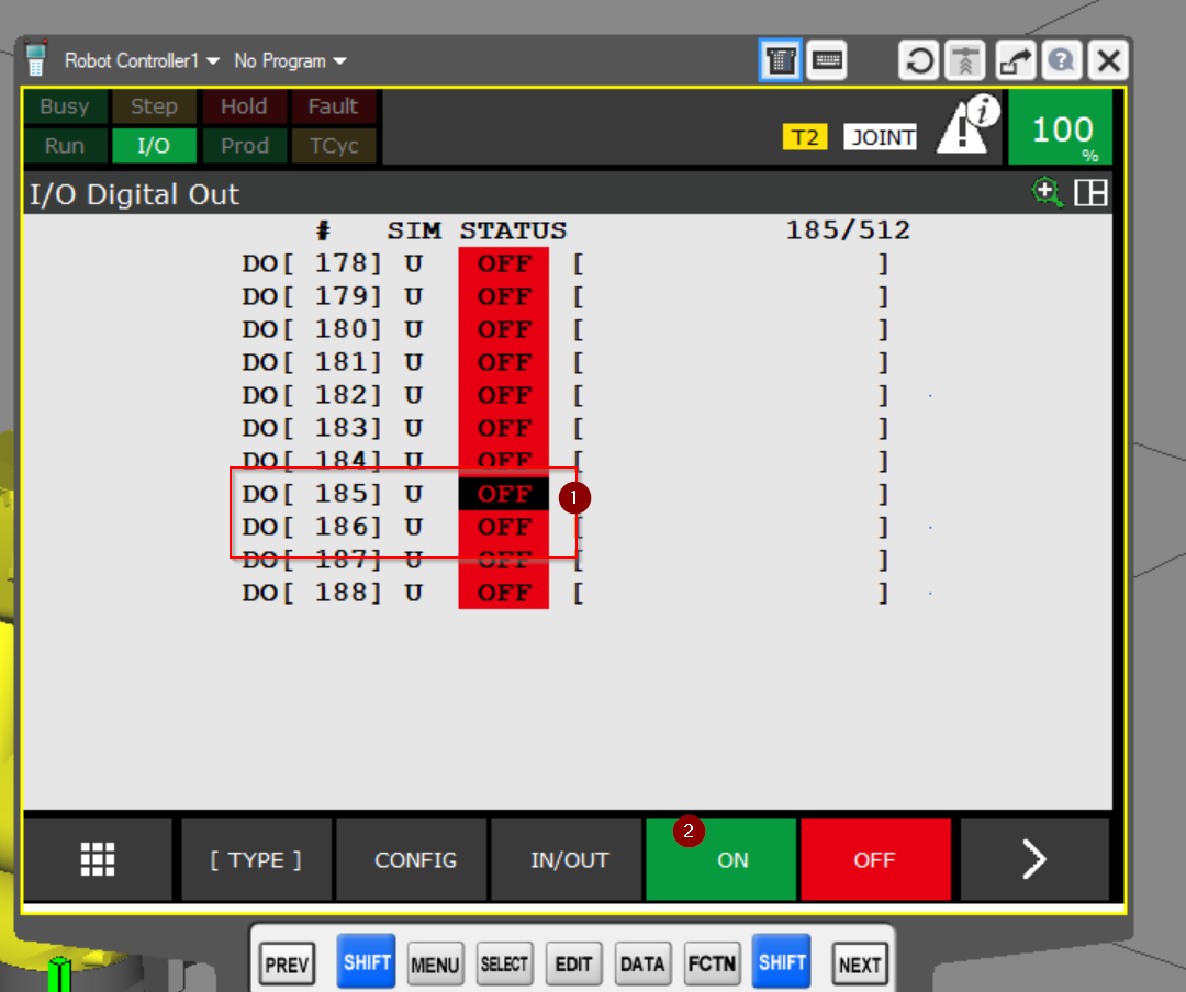
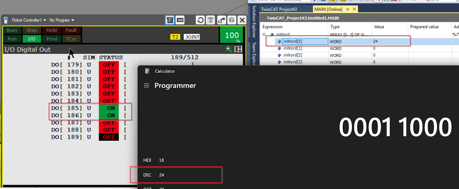
From FANUC side, select DO to turn on DO185 and DO186 and click >ON.
DO185/DO185 is set to True and DEC=24. So the first Word on the TwinCAT side is 24.
DO Word2
DO198/DO199 is set to True and DEC=3. So the second Word on the TwinCAT side is 3.