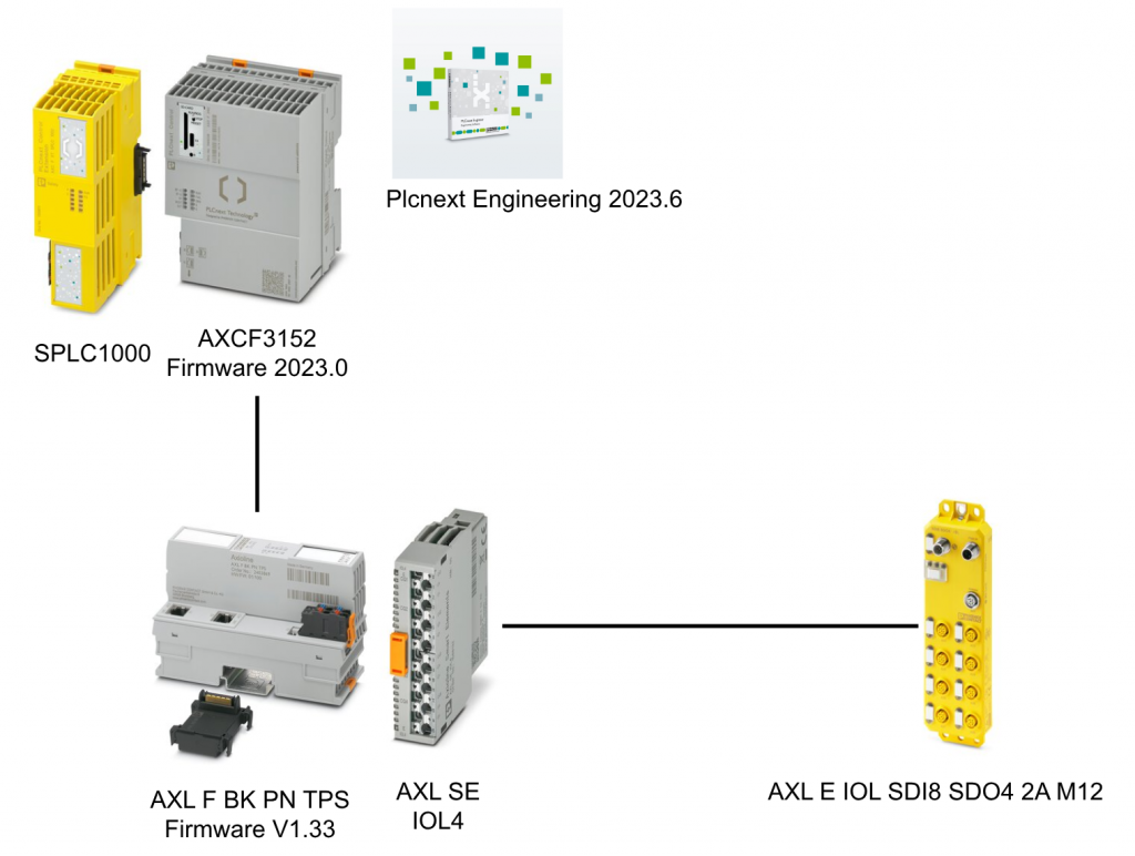
This article will discuss the setup of the AXL E IOL SDI8 SDO4 2A M12 IO-Link Over Profisafe module and AXCF3152, recently launched by Phoenix Contact.
Let’s get started!
Reference Link
Implemenation
Now we can start to implement the project.
Plcnext Side
Import GSDML
Download the GSDML File of AXL F BK PN TPS Bus Coupler from the link below.
https://www.phoenixcontact.com/en-pc/products/bus-coupler-axl-f-bk-pn-tps-2403869

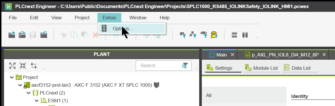
Start Plcnext Engineering and change the Import Option for GSDML, click Extras>Options.
Since AXL E IOL SDI8 SDO4 2A M12 L M12 may not be able to be imported depending on the Version of Plcnext Engineering tool, open GSDML Import>GSDML Import Settings and set the Recommended Profinet Endianness to No.

Click File>Import>Import GSDML File(s) to import GSDML File(s) to import the GSDML file.

Add Profinet
The next step is to build the Profinet network.
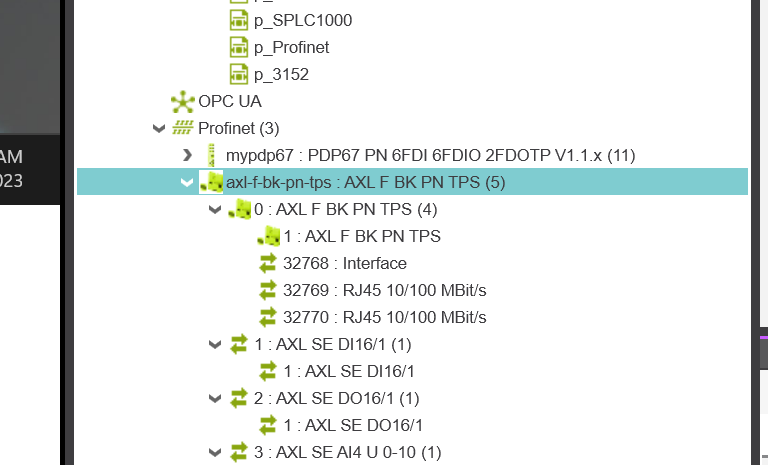
Add AXL F BK PN TPS Coupler
Open the Profinet Device List screen and add the AXL F BK TN TPS to be used this time to Type.
Done!

Configure Network
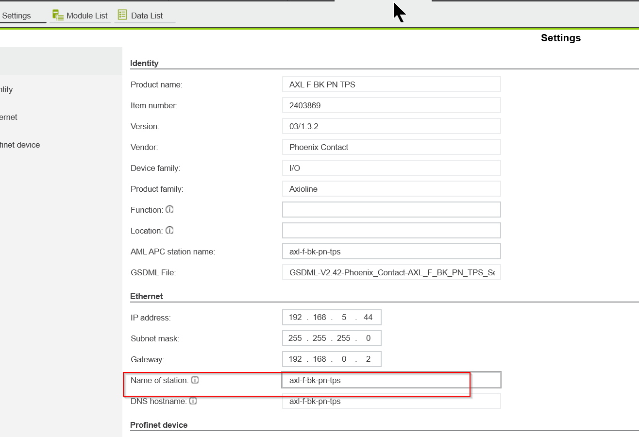
Now we can configure the AXL F BK PN TPS network settings.
IP
Set Ethernet>IP address to match your application.

Station Name
Set the Station name in the Name of Station field as well.
Configure Module
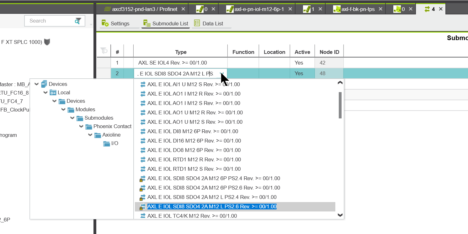
Now open the Module List and set the Smart Elements installed in each Slot.
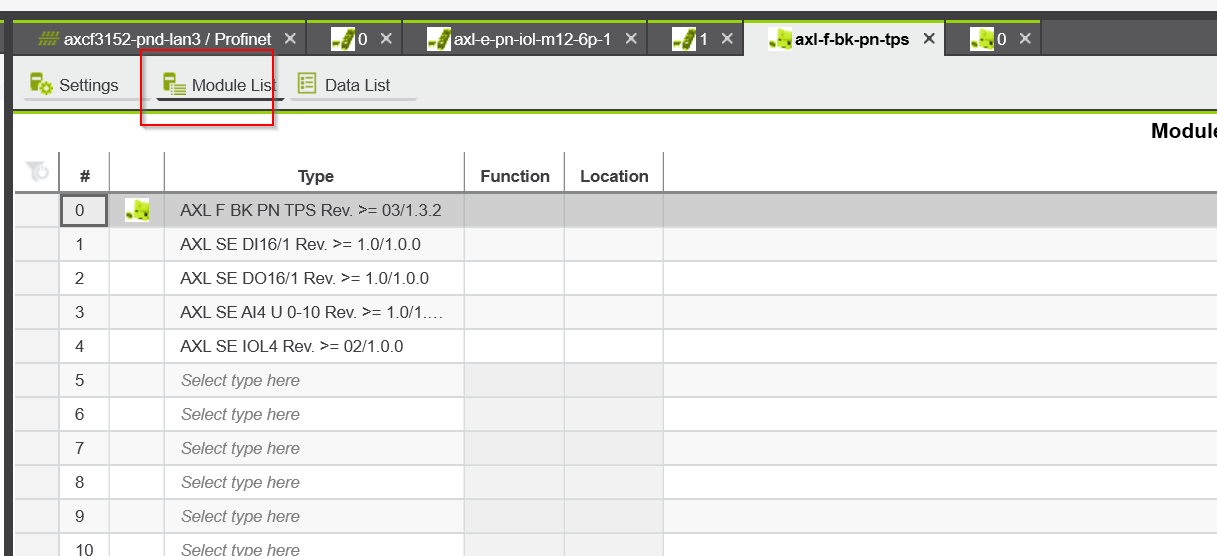
The IOL SDI8 DSO4 2A M12 used in this article is connected via AXL SE IOL4.
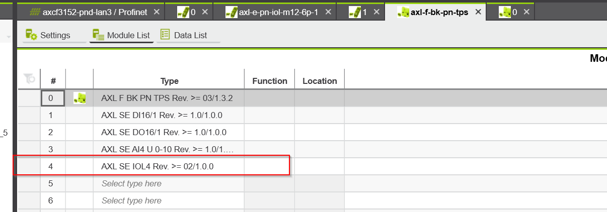
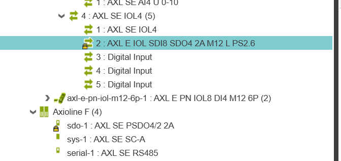
Configure SE IOL4
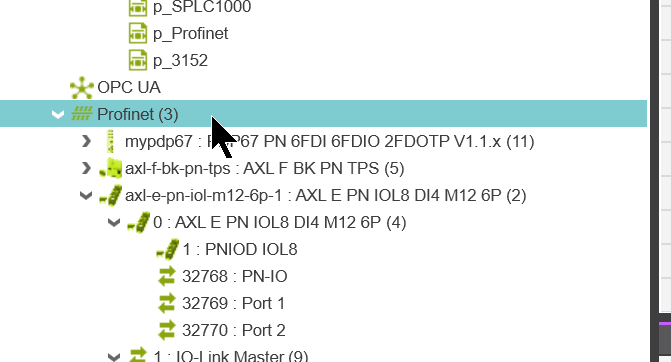
Now we can configure the AXL E IOL SDI8 SDO4 2A M12 that is connected with AXL SE IOL4.
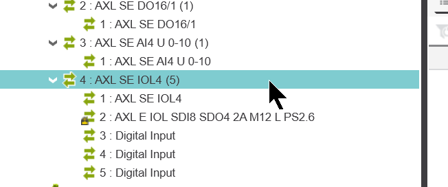
AXL IOL SDI8 SDO4 2A M12 is connected to Channel 1 of AXL SE IOL4, so Slot 4.2 should be set to AXL IOL SDI8 SDO4 2A M12.
Configure AXL IOL SDI8 SDO4 2A M12
The next step is to configure the AXL IOL SDI8 SDO4 2A M12.
Port Configuration
The Parameters will take you to the configuration screen for each Port. The settings here should be set in the same way as when building the Hardware Configuration on a Siemens PLC.
If the parameters are different, the CRCs will not match.

F_iPar_CRC
This is the F_iPar_CRC calculated when building the Hardware Configuration at Siemens.
In Siemens TIA, the CRC value is expressed in hexadecimal.
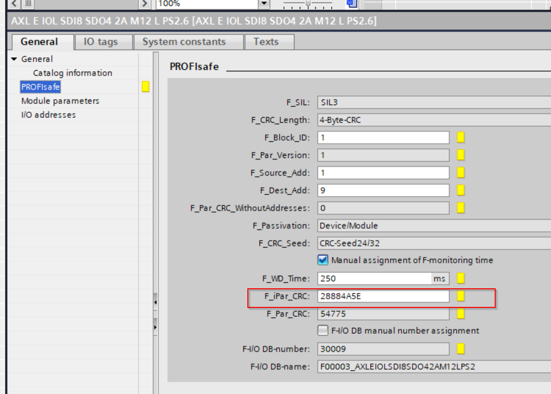
Plcnext Engineeringでは10進数でCRC値を表現しますので、PCの電卓アプリなどで10進数に変換しSafety ParametersのF_iPar_CRCに設定しましょう。
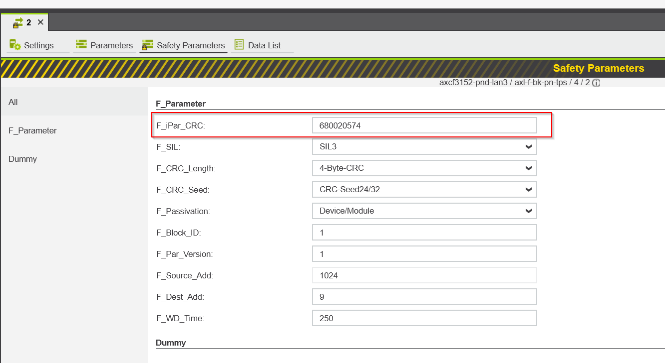
F_Dest_Add
F_Dest_Add should also be set to the Profisafe address that you set when you built the Hardware Configuration in your Siemens PLC.
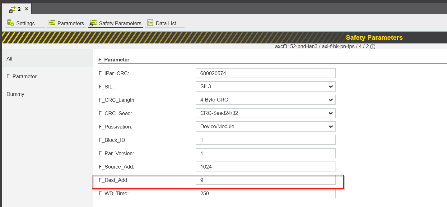
This is the Profisafe address that was set up using Siemens FunctionBlock in the previous article.

Mapping
Next, Mapping the required safety variables in the Data List.

Safety Program
Now open Safety PLC>SafetyTask>S_Main to create a simple safety programme.

Here is just a sample program that shows that the output of Channel0 is true, while the input of Channel0 is True.

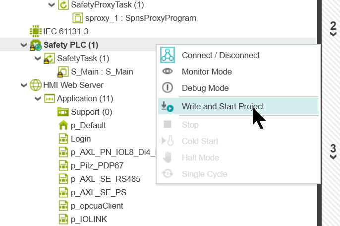
Download
Finally, to download the Safety project to the SPLC, click on Safety PLC>Right-click>Connect/Disconnect to connect to the SPLC1000.

Click on Write and start Project and download the Safety project.
Result
Click on Safety PLC to check the current status of the SPLC1000.

The Safety Cockpit allows you to check the current status of the SPLC1000, Status=Safety Run, which means that the SPLC1000 is in normal status.

You can check the operation from this video.
コメント
Hi there! Your tutorials are so helpful 🙂
I have a similar setup with axl e iol sdi sdo m12 L to an iol4 on the profinet extender (bk pn tps) but I only have a axc2152 plc not a siemens to do the setup.
Connecting it all up the iolink master says
API: 19969 / Slot: 1 / Subslot: 1 / Channel: 1
Lower-level bus: no module present (0x2001)
Do you have any tips on how to communicate / fault find this?
I don’t know if its because I don’t have the CRC setup that you obtained from your siemens plc?
Thank you!