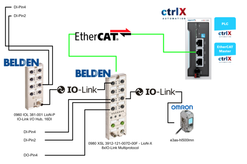
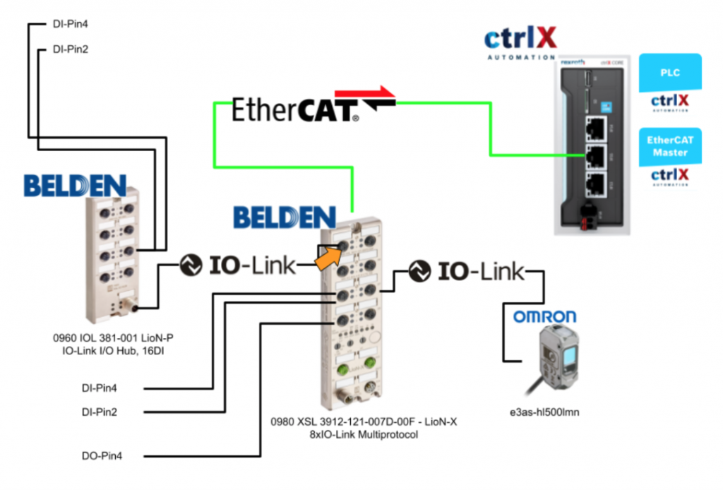
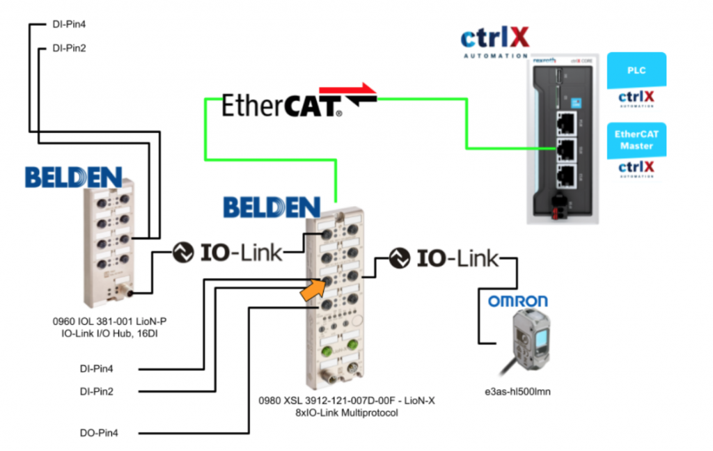
This article provides guidelines for using Bosch Rexroch’s ctrlX X3 to connect to BELDEN’s IO Link Master 0980 XSL 3912-121-007D-00F – LioN-X 8xIO-Link.
Let’s get Started!
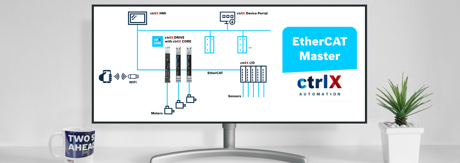
EtherCAT Master App?
The EtherCAT Master App activates the master interface of the real-time Ethernet system EtherCAT and connects ctrlX CORE with ctrlX DRIVE and a wide range of devices in the EtherCAT ecosystem. Data is available to all apps on ctrlX CORE via the real-time data layer.
The EtherCAT Bus System is configured with the ctrlX IO Engineering software; the EtherCAT Master App requires the “Automation Core” app.
EtherCAT Master supports the following functions:
- Communication to ctrlX DRIVE via SoE
- Communication with IO and other automation devices via CoE
- Synchronous communication via distributed clock
- Engineering of EtherCAT Slave via EoE
Slave
An EtherCAT network can consist of a master and up to 65535 slaves.
The topology can also be implemented arbitrarily, e.g. using junction terminals. When actually wiring, note that the EtherCAT Slave has only one defined input port. This is usually port 0 and is labeled “IN”.
Most EtherCAT Slaves have 1 “IN ports” and 1 “OUT port”.
In the case of other bus couplers that use the E-BUS as a backplane bus, the Ethernet telegram is an EtherCAT Slave that is routed via this backplane bus (E-BUS). In this case, each module (terminal) is a slave with IN and OUT ports, and the E-BUS bus coupler or junction terminal has three or four ports (= multiple output ports).
SlaveA – modular bus coupler
This is a modular bus coupler according to the “Modular Device Profile”, where all expansion modules are connected to a device-specific backplane bus with a bus coupler. That type of modular bus coupler is a slave device in the network and stores all I/O data of the module.
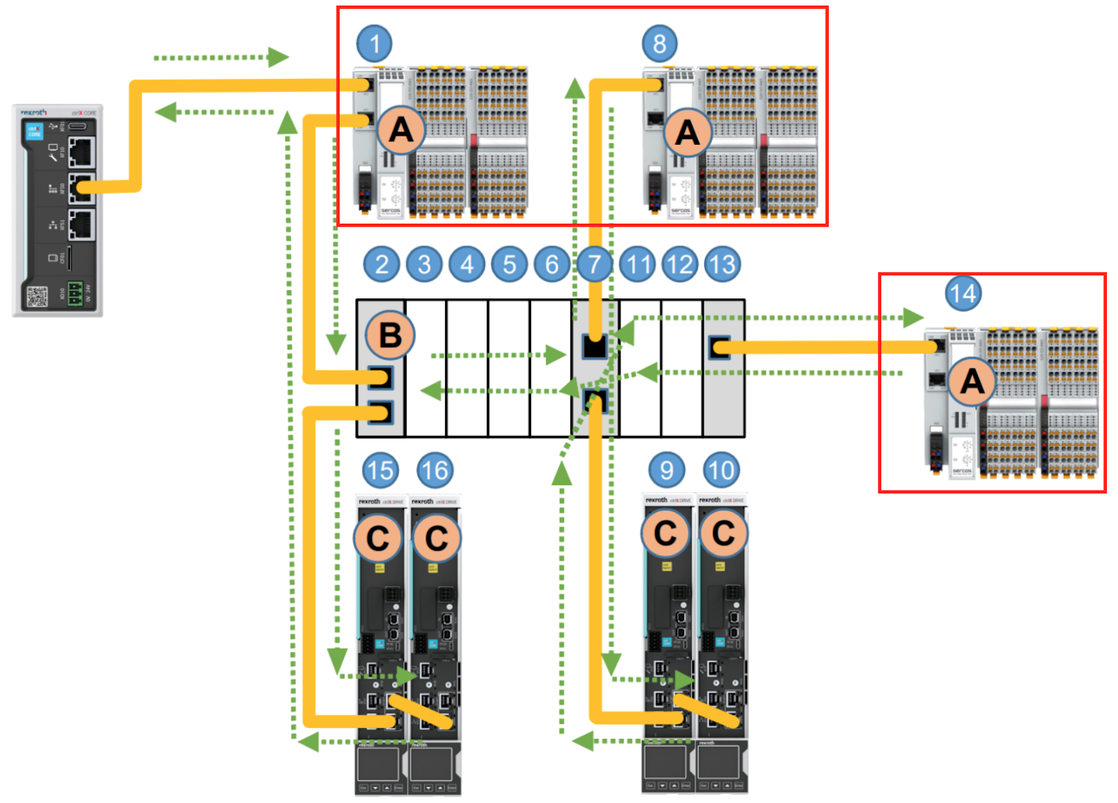
SlaveB – modular System with E-BUS
It is a modular system using E-BUS (e.g. Beckhoff EK1100), where each module
Each module, bus coupler, junction terminal and extension terminal represents a slave device on the EtherCAT network.
SlaveC Drive
This is the EtherCAT Drive Slave.
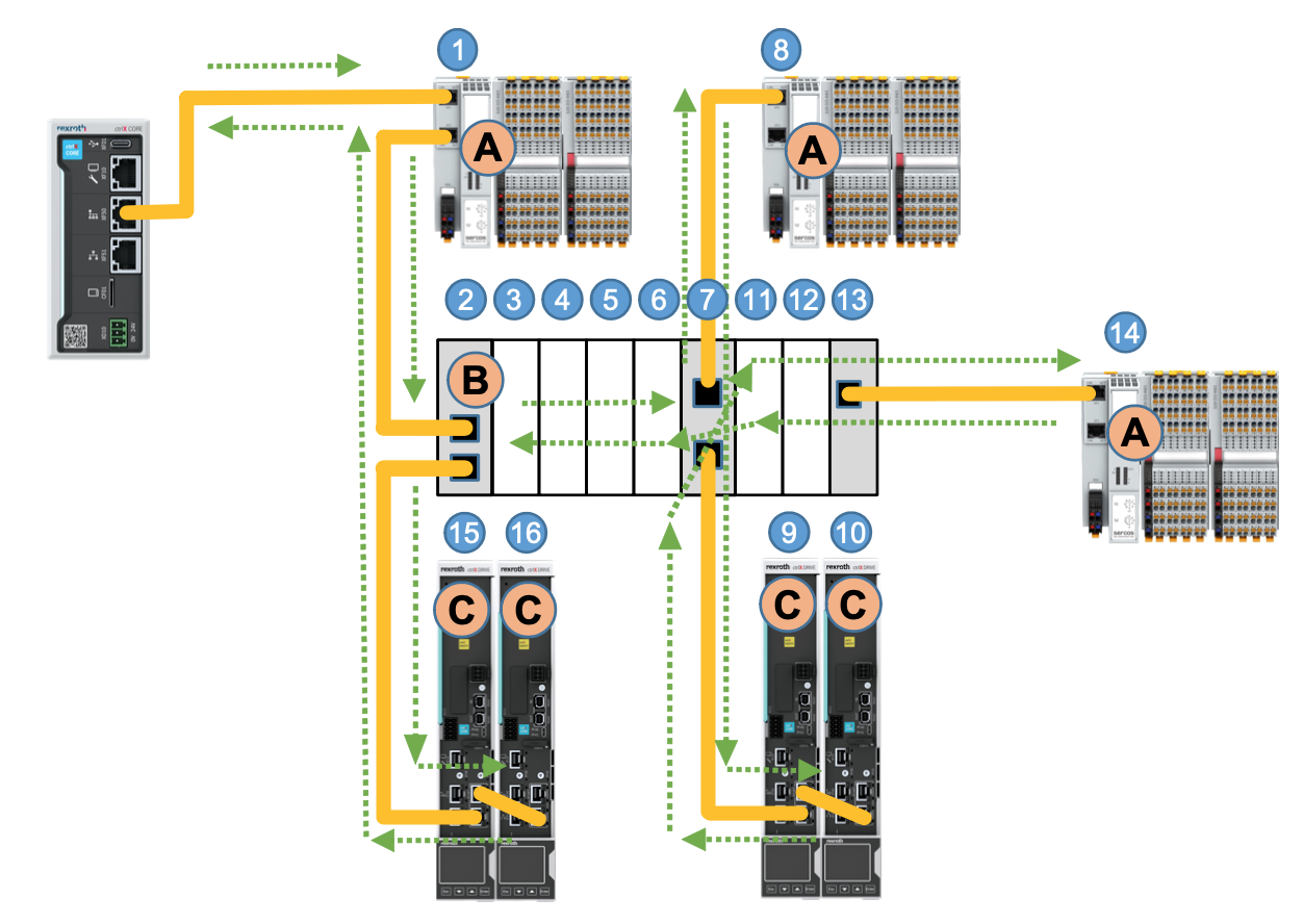
Telegram
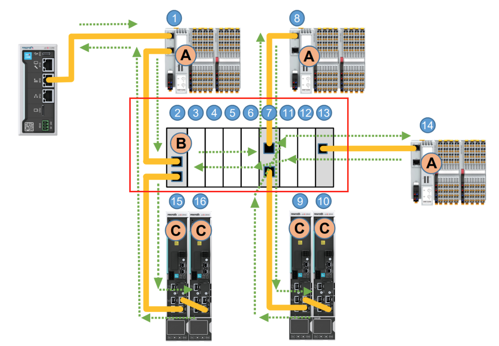
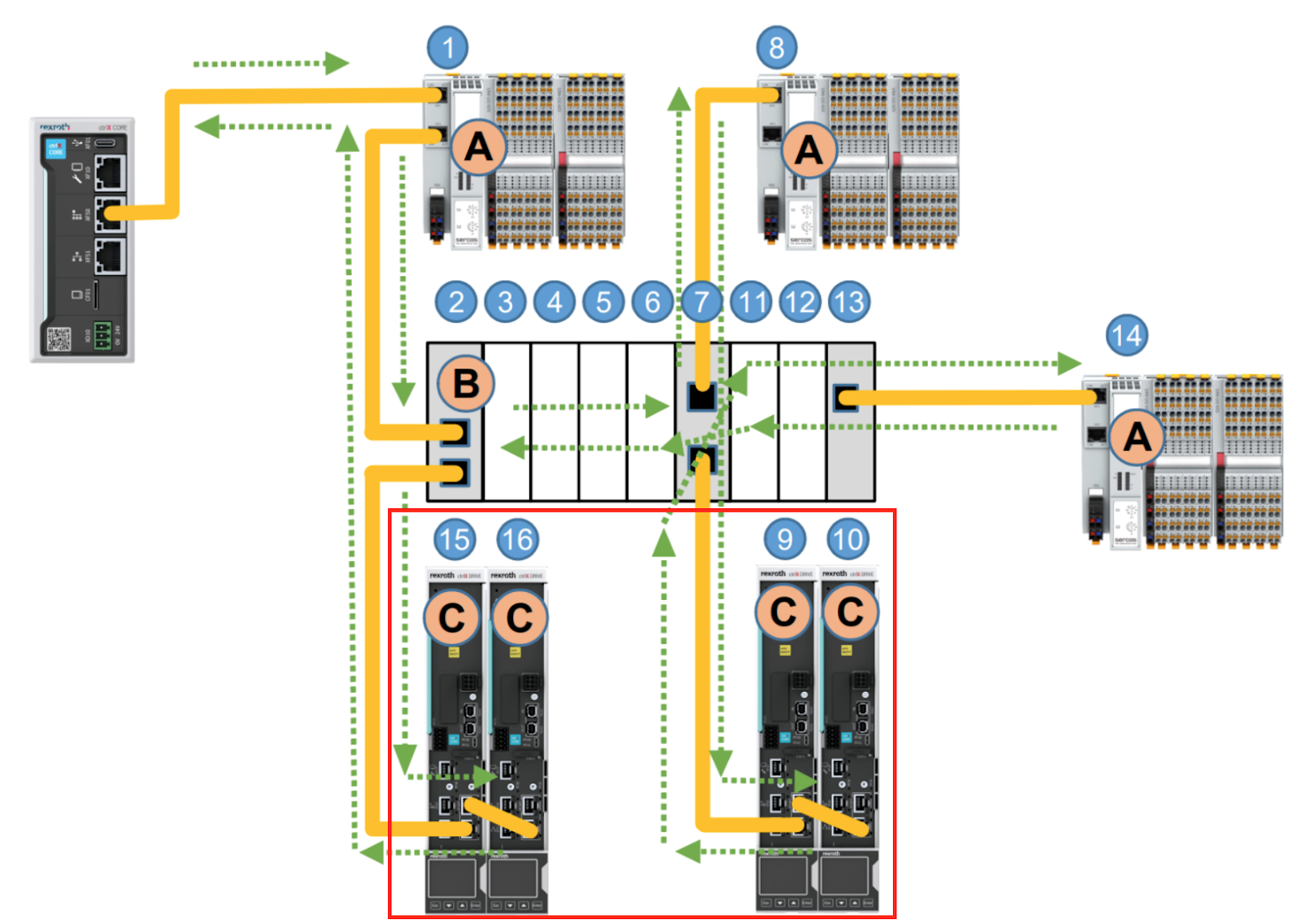
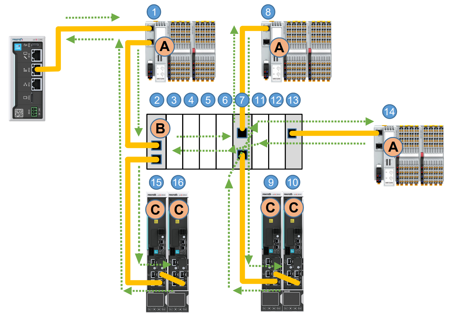
EtherCAT telegrams are sent from the master and pass through all slave devices.In the EtherCAT Slave Controller (ESC), input and output data are only processed in the forward direction.
The last slave device only sends the telegram back to the master and does not process it.
The figure below shows the numbers from (1) to (16) in the logical sequence of EtherCAT telegrams passing through a slave device.
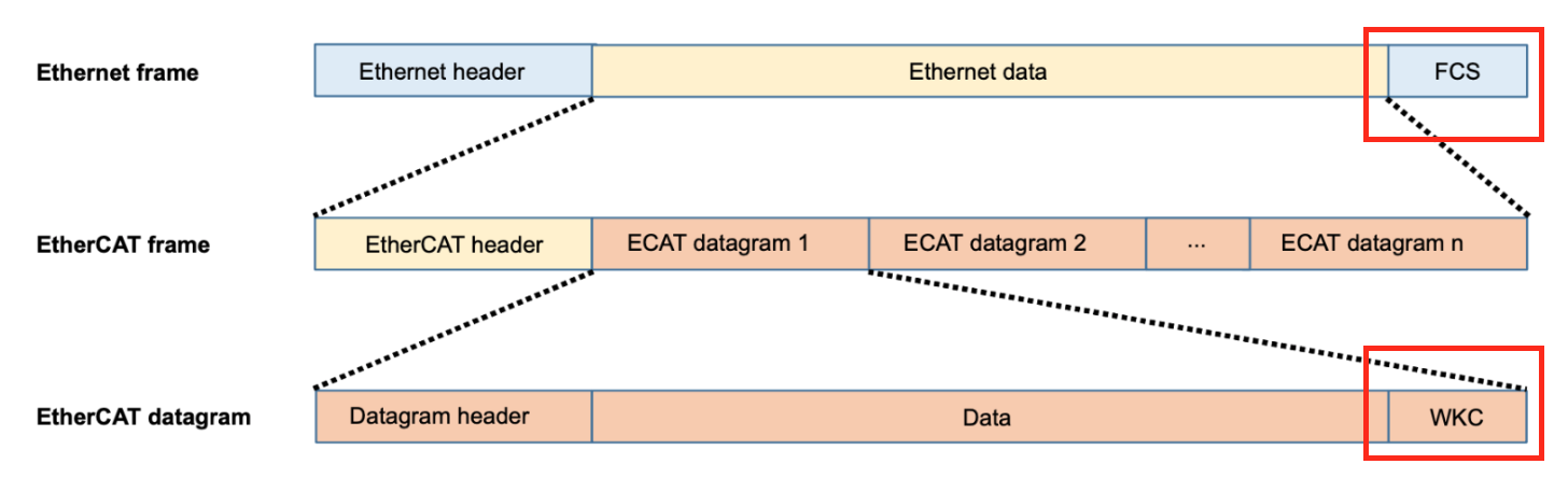
Structure
EtherCAT uses standard Ethernet frames (IEEE 802.3) with EtherType 0x88A4. It should be noted that other types of Ethernet telegrams are essentially not supported by the EtherCAT Slave Controller and must be Transferred with EtherCAT (e.g. EoE).
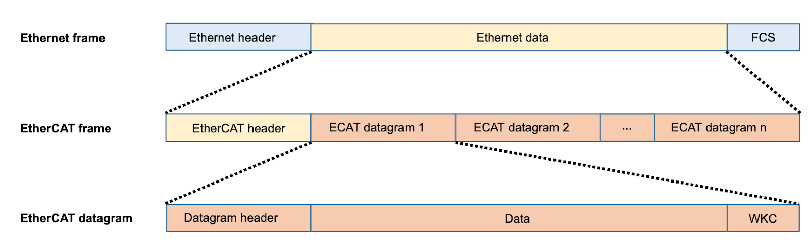
Working Counter
The Checksum (FCS : Frame Check Sequence) of the Ethernet frame guarantees correct data transfer to the Bus, but to check the correct command execution of the slave device, each datagram has a WorkingCounter (WKC). WKC is sent by the master with the value 0. Each addressed slave increments the WKC with respect to the command.
After the frame has passed through all the slaves and reached the master again, the master can verify correct command processing by comparing the expected (command value) and actual values of WKC.
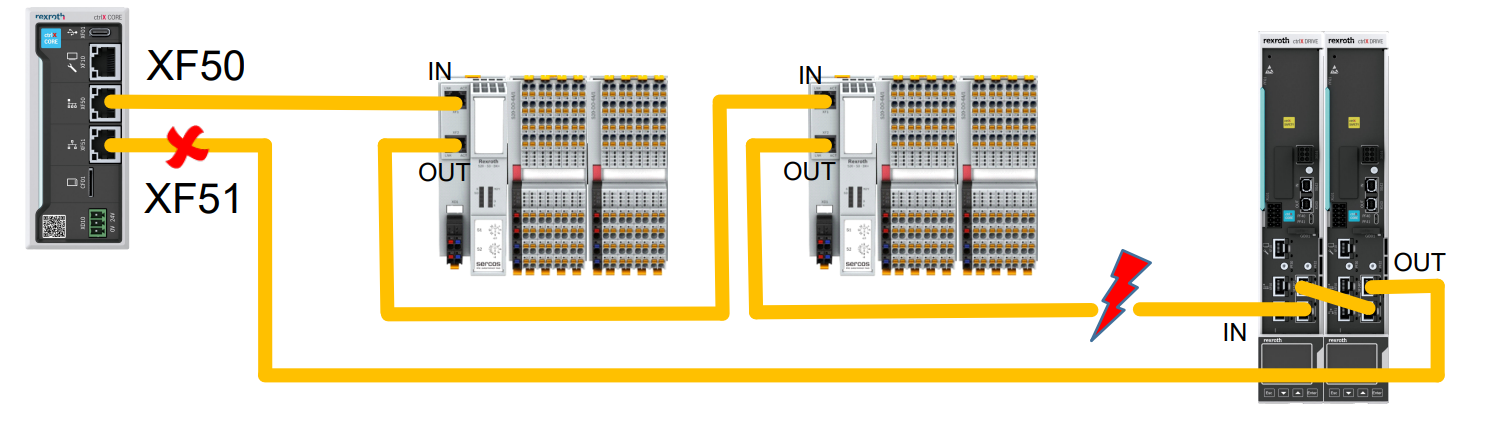
Cable redundancy In ctrlX CORE
With EtherCAT, redundancy is only possible in a ring topology, where theoretically the last slave device is wired to the master at the second Ethernet port.
But the Rexroth EtherCAT master does not support cable redundancy.
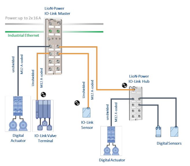
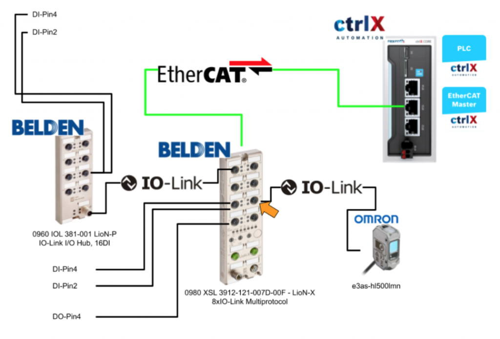
IO-Link basics
IO-Link is a globally standardized technology that enables communication between devices ranging from complex, intelligent sensors to central control units.
An IO-Link system consists of an IO-Link master and IO-Link devices (sensors, actuators, valves, I/O modules, etc.).
The IO-Link Master provides the interface to the host controller and controls communication with the connected IO-Link devices. The connection between the Master and the devices can then be realized with standard unshielded connection cables.
The IO-Link Master can have multiple IO-Link ports, and IO-Link devices can be connected to each port. This connection is also called Point-to-Point communication.
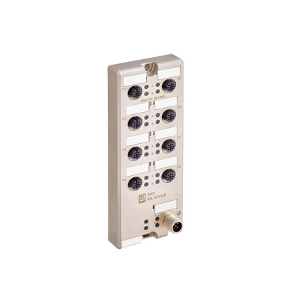
0980 XSL 3912-121-007D-00F – LioN-X 8xIO-Link?
LioN-X and LioN-Xlight will be comprehensive devices that can convert standard input, standard output, or IO-Link signals from sensors and actuators to industrial Ethernet protocols (PROFINET, EtherNet/IP, EtherCAT®, Modbus TCP, CC-Link IE Field Basic) and cloud protocols (REST API, OPC UA, MQTT).
The LioN-X and LioN-Xligh’s robust 8-port enclosure design allows them to be used in harsh environments with welding resistance, high temperature range, and protection classes IP67 and IP69K.
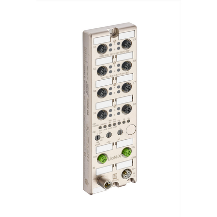
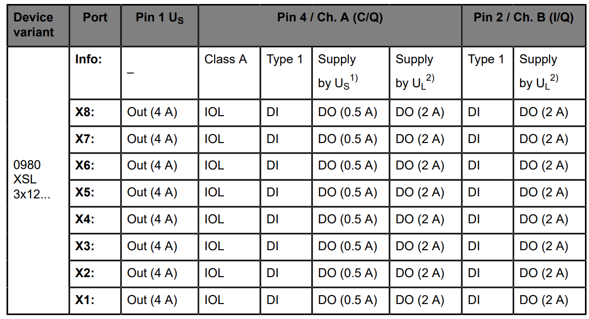
I/O port overview
LioN-X supports IO-Link specification v1.1.3. The following figure shows the mapping of 0980 XSL 3×12….
Port Assign
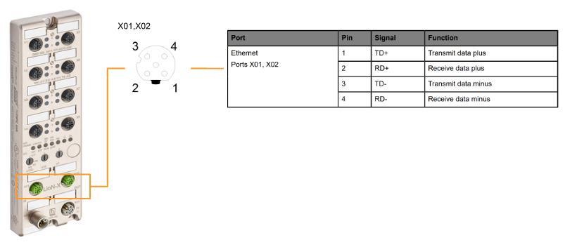
X01/X02 will be Ethernet ports, 4-pin, D-coded with M12 socket.
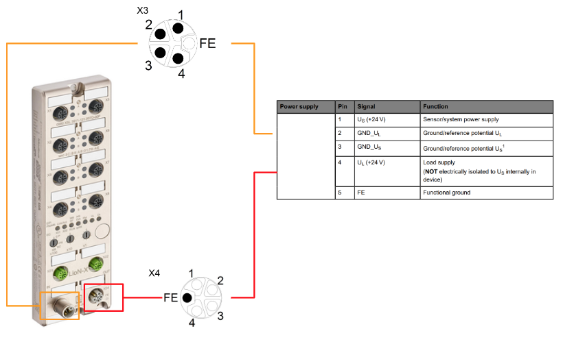
X03/X04 will be L-coded for Power supply, M12 Power.
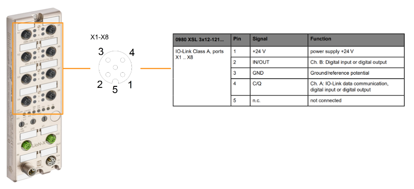
X01-X08 will be A-coded for IO-Link Port ,M12 Power.
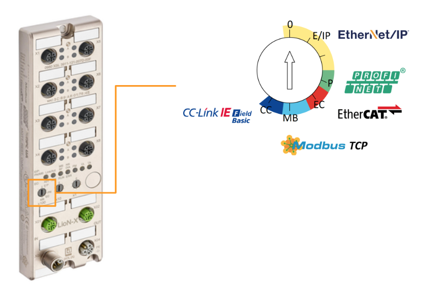
Rotary encoding switches
The 0980 XSL 3912-121-007D-00F supports the following Industrial protocols, and the LioN-X multi-protocol variant offers a choice of different protocols for communication within an Industrial Ethernet system.
- EtherNet/IP (E/IP)
- PROFINET (P)
- EtherCAT® (EC)
- Modbus TCP (MB)
With multi-protocol capability, the Master can be integrated into different networks without the need to purchase products dedicated to each protocol. This technology allows the same IOL-Master to be used in different environments.
The rotary encoding switch on the bottom front of the device is used to easily and conveniently set both the protocol and address of the device.
Note that a power cycle or reset from the web interface is required to apply the changed rotary encoding switch settings (protocol settings).

Factory reset
To restore the factory settings, reset any previous changes or settings: set the Rotary encoding switch to x100=9, x10=7, and x3=9. Then turn the power back on and wait 10 seconds for the internal memory write process.

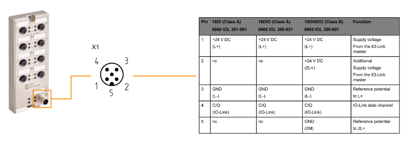
0960 IOL 381-001 – LioN-P,IO-Link I/O Hub,16DI ?
The IO-Link module 0960 IOL 381-001 with 16 digital inputs receives binary sensor signals from the process level and transfers them to the PLC control system via the IO-Link master and higher-level Field bus.
Each sensor is powered from the supply voltage (L+) provided by the IO-Link master and does not require a separate supply voltage connection.
Port Ovweview
X1 will be IOLink ports, M12 5-pin, D-coded.
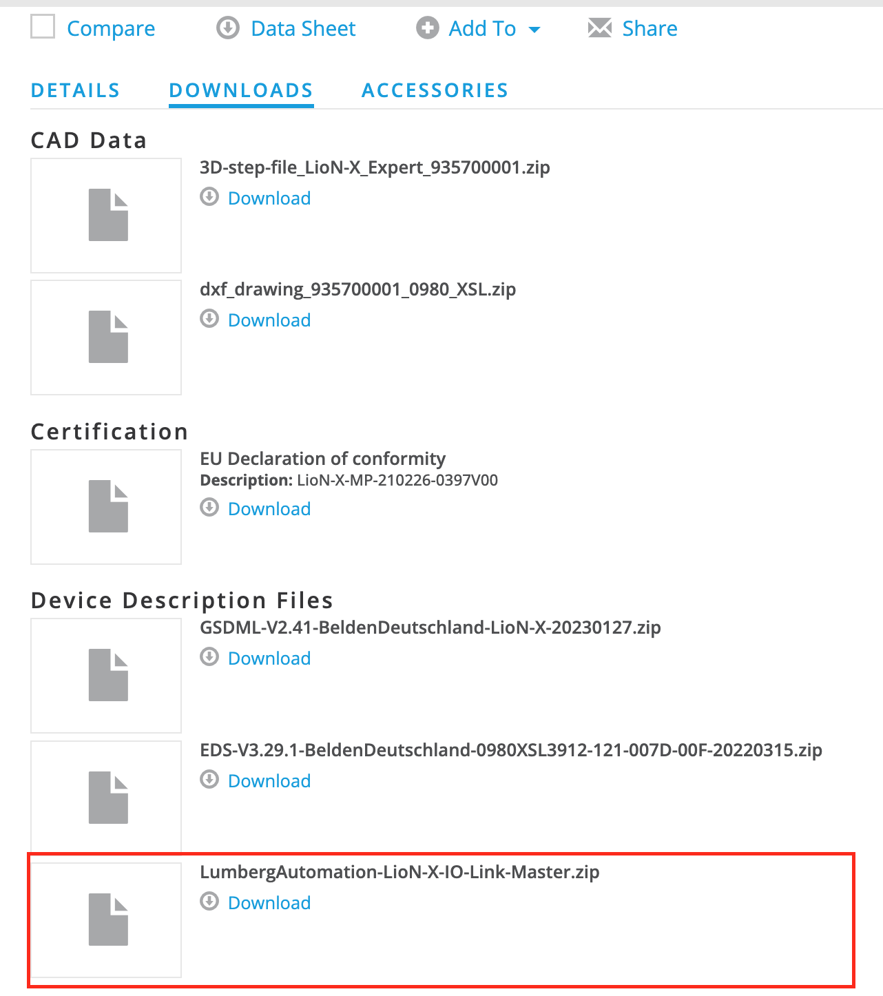
Download ESI File
Download the ESI File needed to build an EthereCAT network from the link below.
https://catalog.belden.com/index.cfm?event=pd&p=PF_0980XSL3911121007D00F
Implementation
BELDEN Side
0980 XSL 3912-121-007D-00F – Set the rotary switch on the body of the LioN-X 8xIO-Link to “EC”.
ctrlX Side
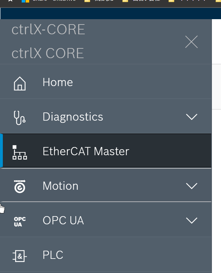
EtherCAT Master
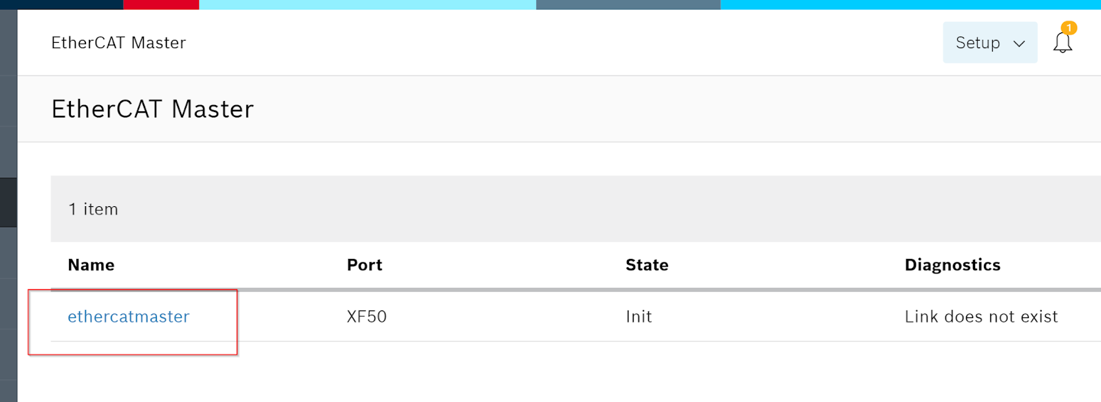
As we are going to create an EtherCAT network from the EtherCAT Master Apps, please access the ctrlX PLC Web Server and click on EtherCAT Master.
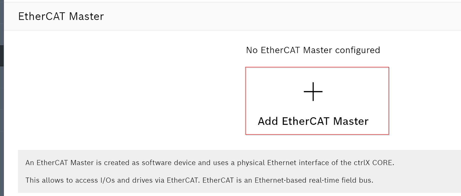
Click on Add EtherCAT Master to add an EtherCAT Master.
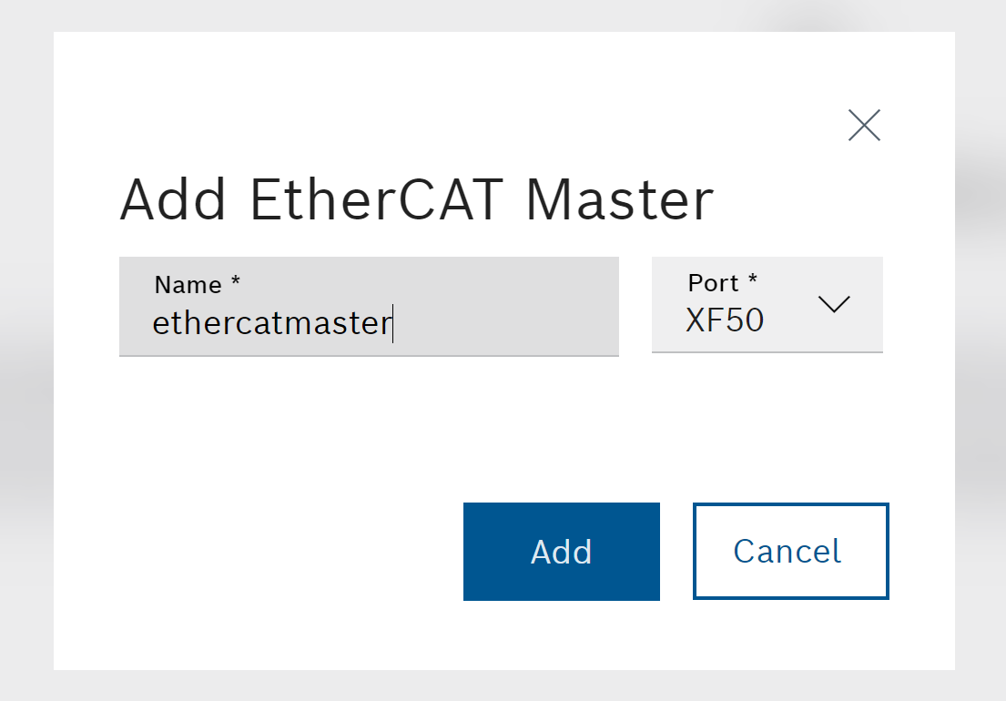
Set the EtherCAT Master name and the Port to be used.
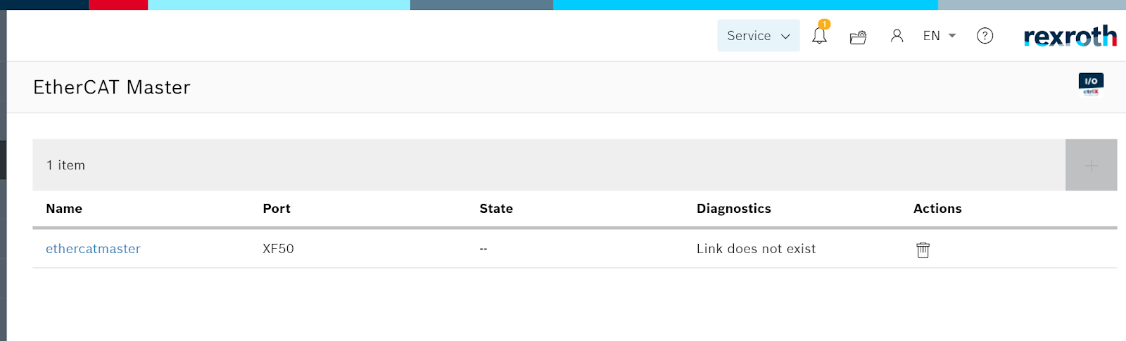
Done!EtherCAT Master has been added.
Start ctrlX I/O Engineering
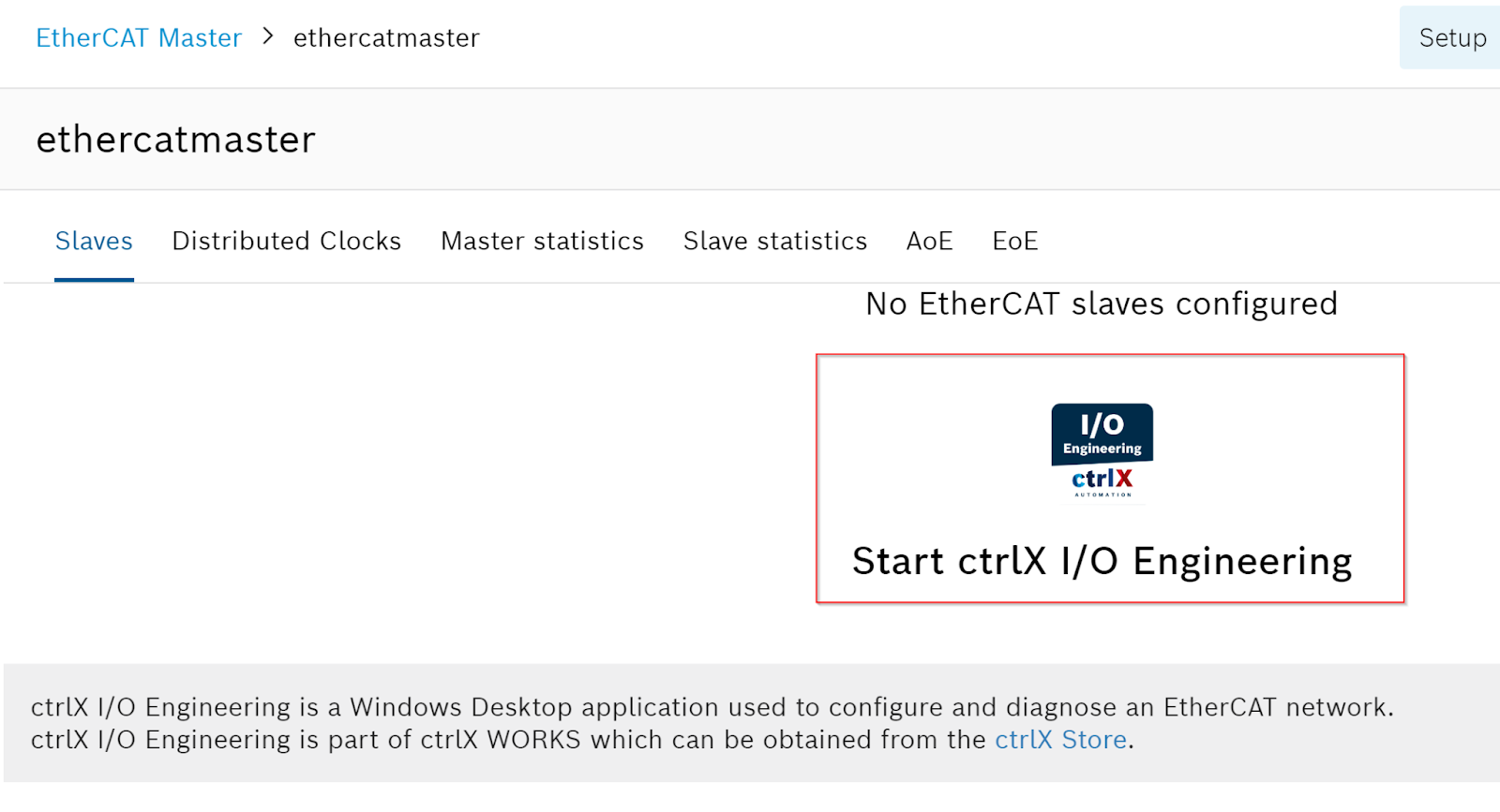
To build an EtherCAT Master with ctrlX, you need ctrlX I/O Engineering. Click on the EtherCAT Master that has just been added.
Click on Start ctrlX I/O Engineering.
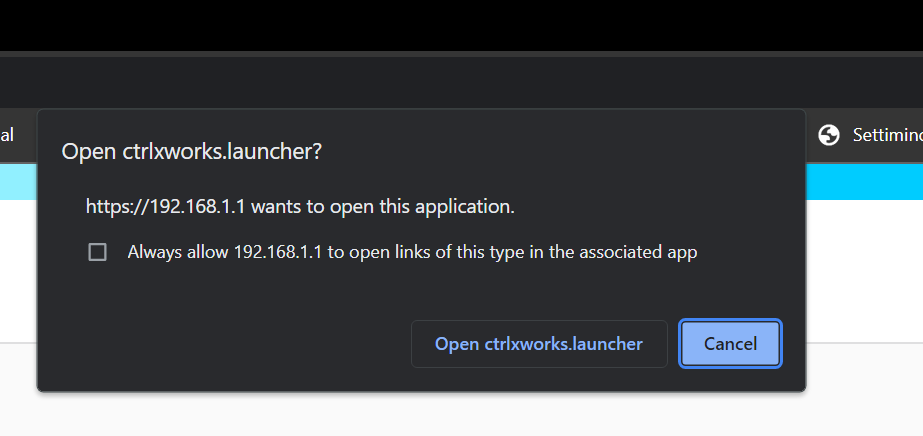
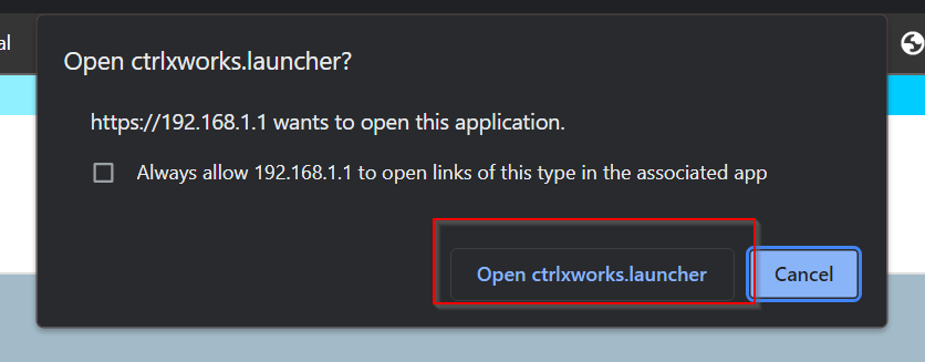
Click on Open ctrlxworks launcher.
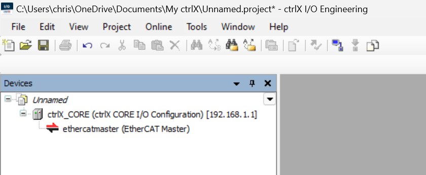
Done!ctrlX I/O Engineering will start and let’s create a new project name.
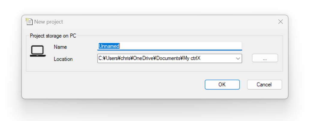
Done!
Device Repository
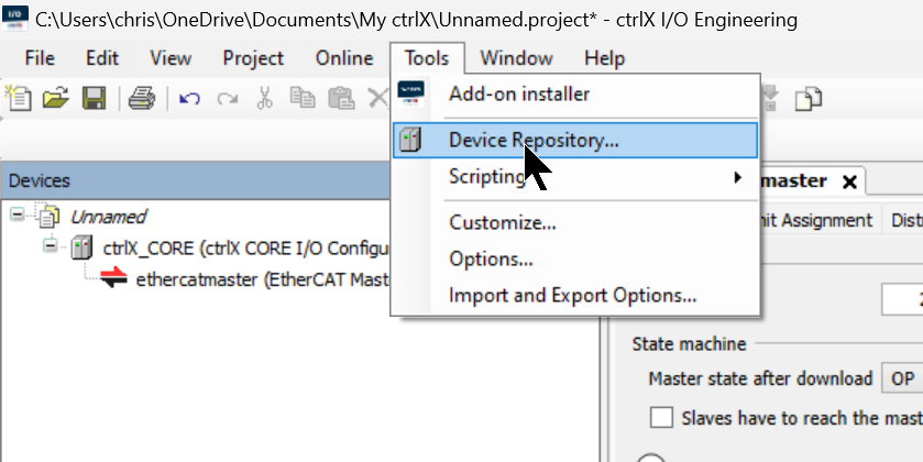
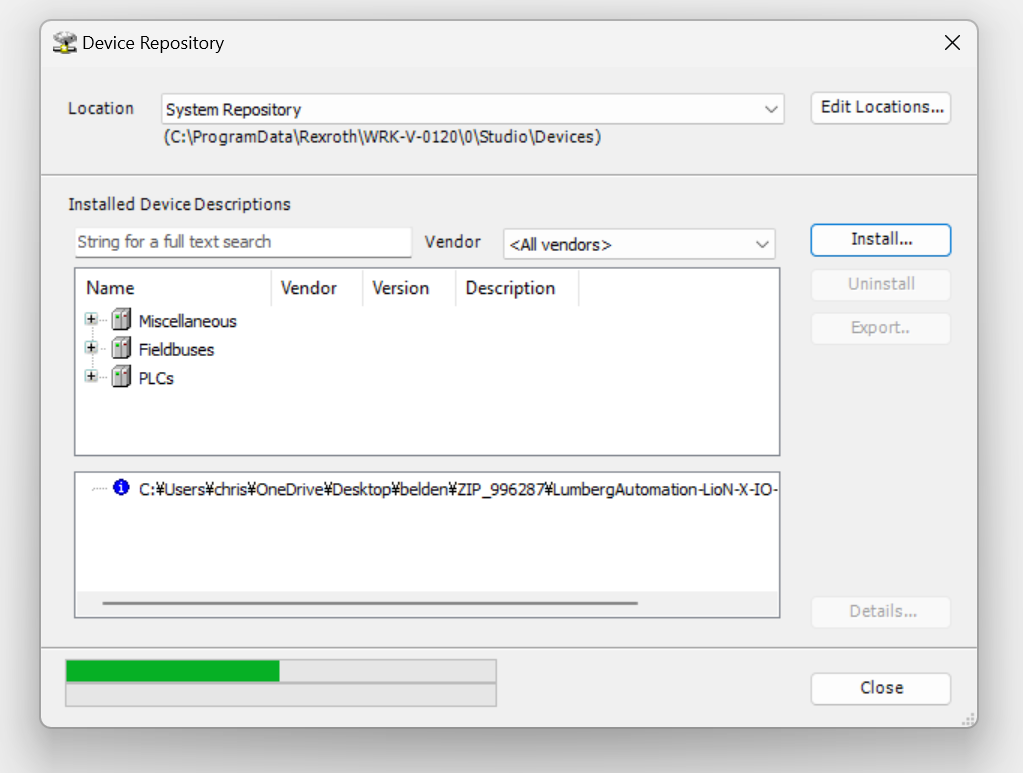
Open Tools>Device Respository to install the ESI File in ctrlX I/O Engineering.
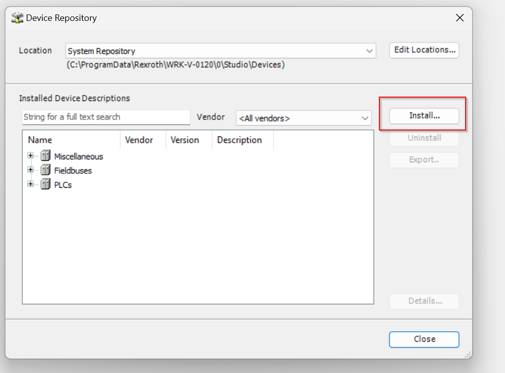
The Device Repository management screen appears and click the Install button.
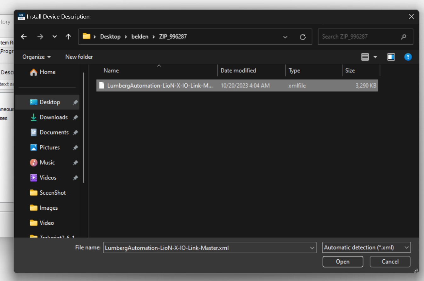
Select the ESI File you have just downloaded.
Just a second..
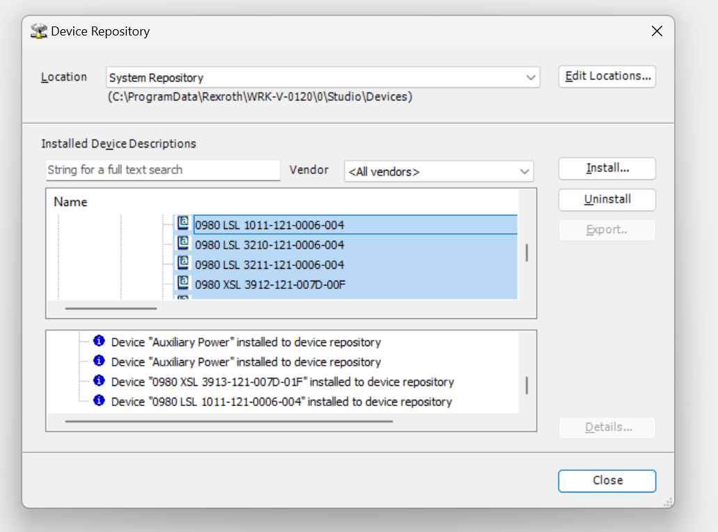
Done!ESI File is now installed.
Add Device
Next, to add 0980 XSL 3912-121-007D-00F, ethercatmaster>right click>Add Device.
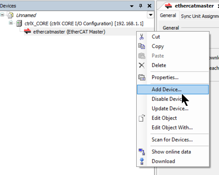
The Add Device screen appears.
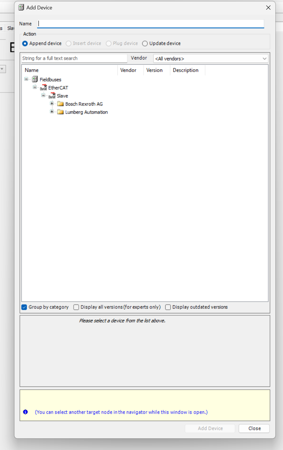
Select 0980 XSL 3912-121-007D-00F for use in this article > Add Device.
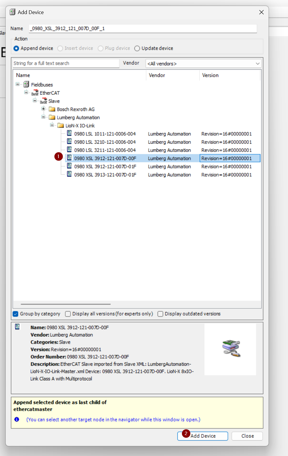
Done!0980 XSL 3912-121-007D-00F has been added to etherecatmaster’s network.
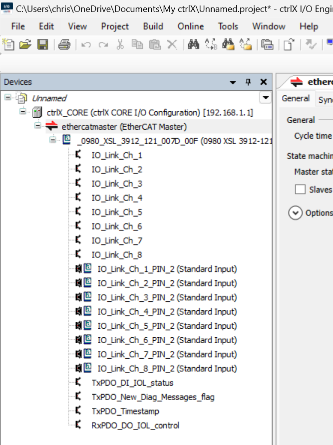
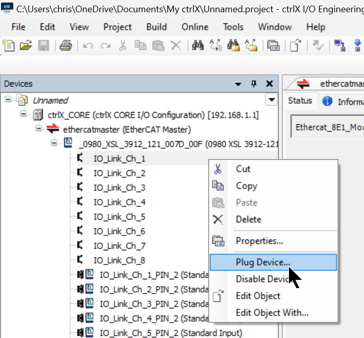
Plug Device
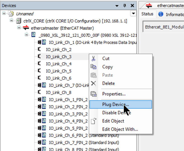
Now right-click on each slot > Plug Device to add the necessary devices to each slot.
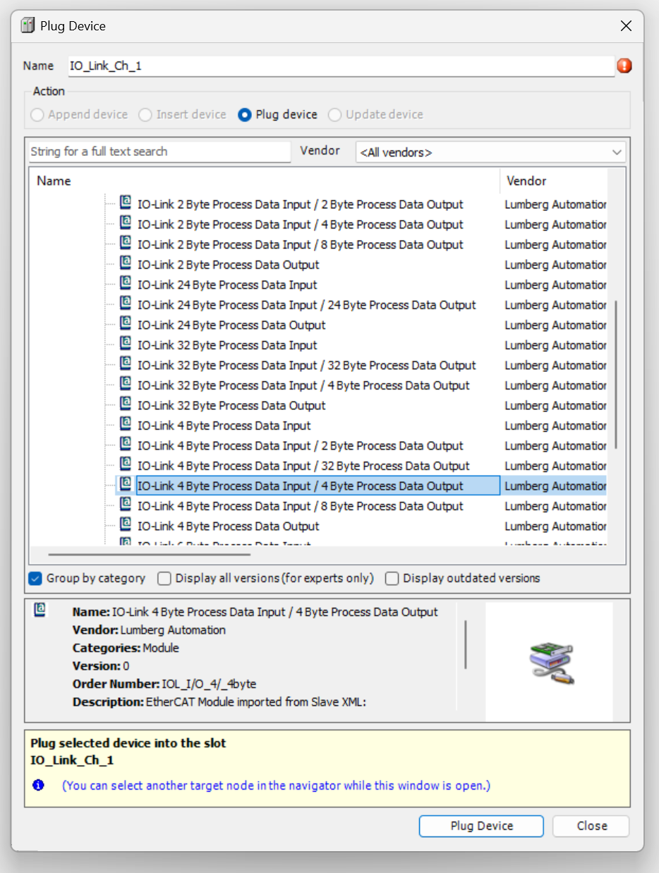
Plug Ch1
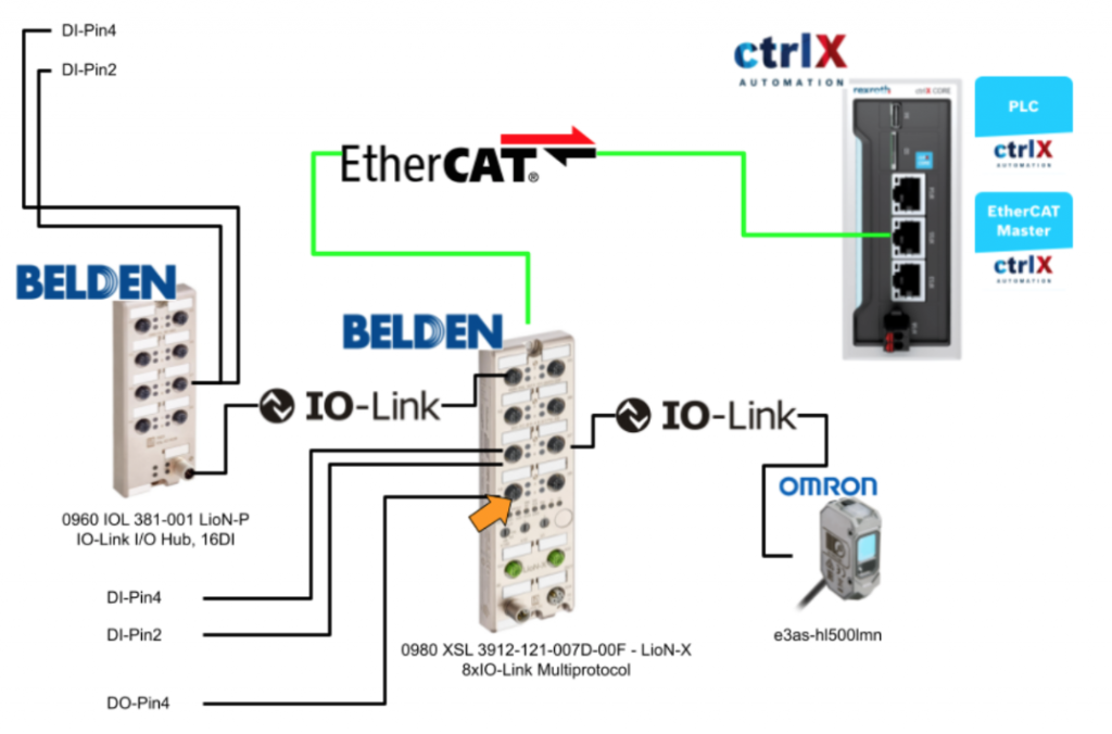
Channel 1 is connected to 0960 IOL 381-001 – LioN-P, IO-Link I/O Hub, 16DI.
Add IO-Link 4 Byte Process Data Input/ 4 Byte Process Data Output from Device List.
Plug Ch3
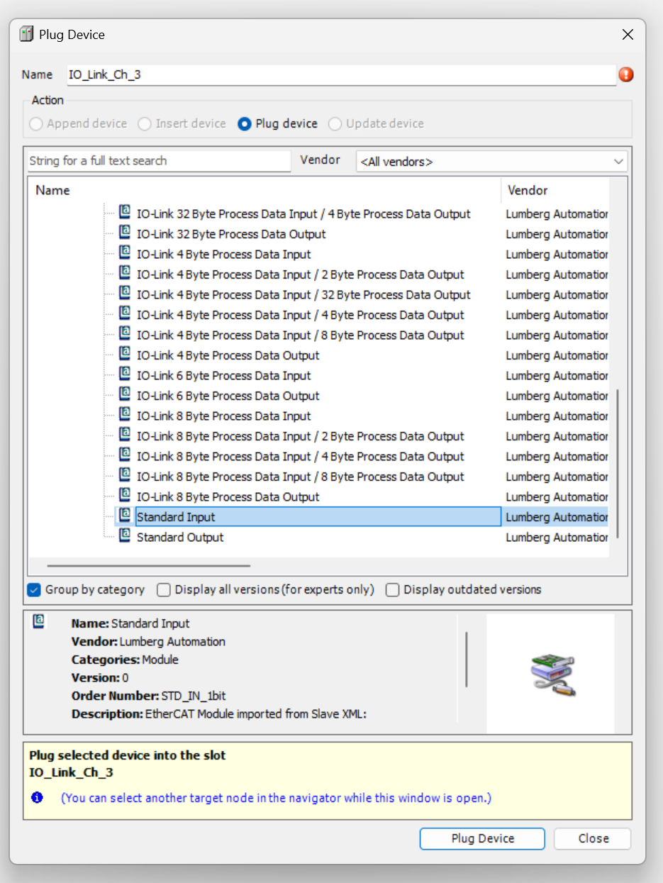
Pin 2 and Pin 4 of Channel 3 are connected to the digital inputs.
Right click on IO_Link_Ch3>Plug Device.
Select Standard Input > Plug Device.
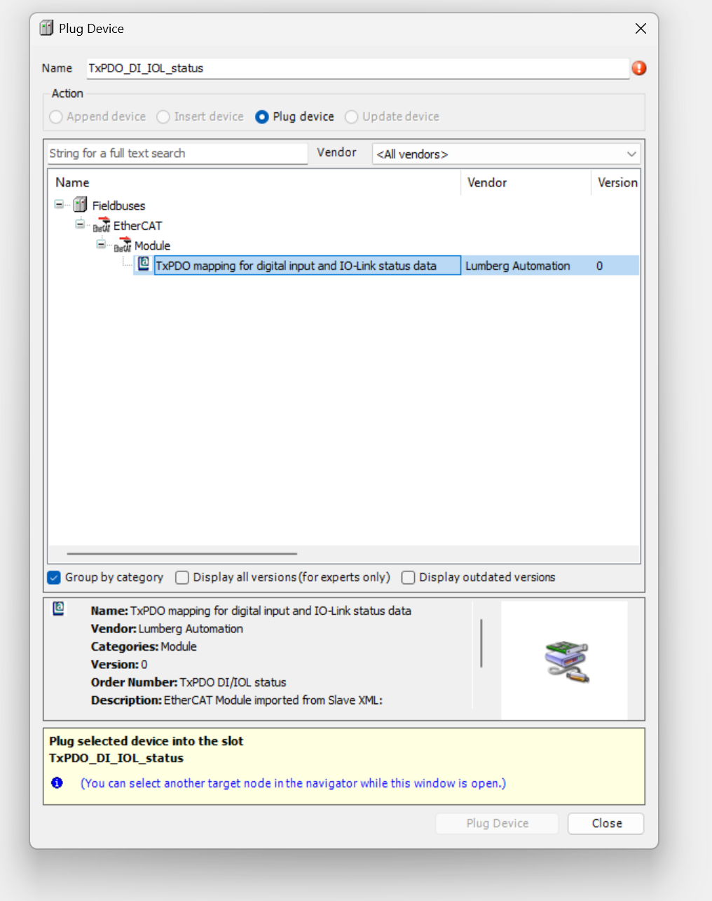
However, if you want to get Pin2 data, you need to plug the device into TxPDO_DI_IOL_status as well, so please right click on TxPDO_DI_IOL_status>Plug Device.
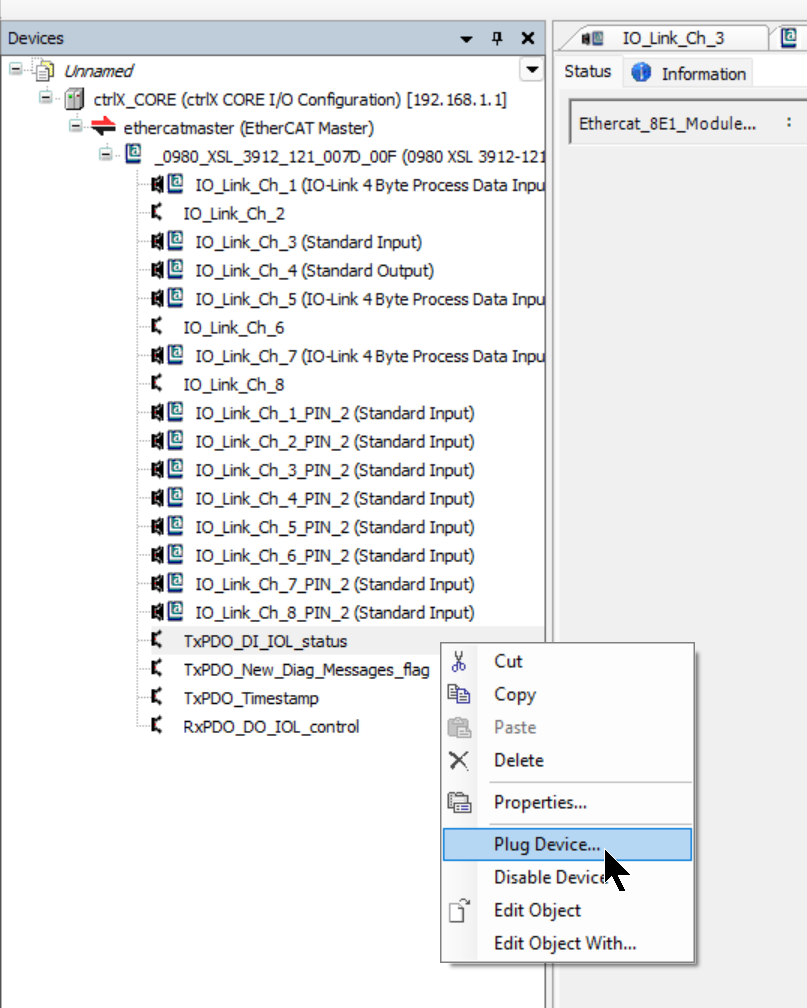
Add a Slot for TxPDO mapping for digital input and IO-Link Status data. This slot can be used to check the input status of not only Slot 3 but also other slots at once.
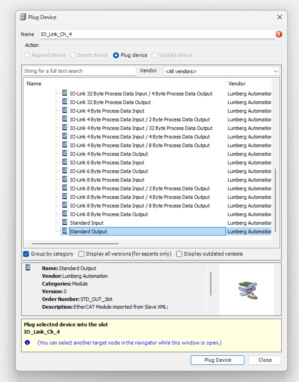
Plug Ch4
Channel 4 is connected to the digital output.
Right click on IO_Link_Ch4 > Plug Device.
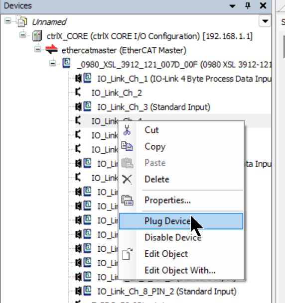
Select Standard Output>Plug Device.
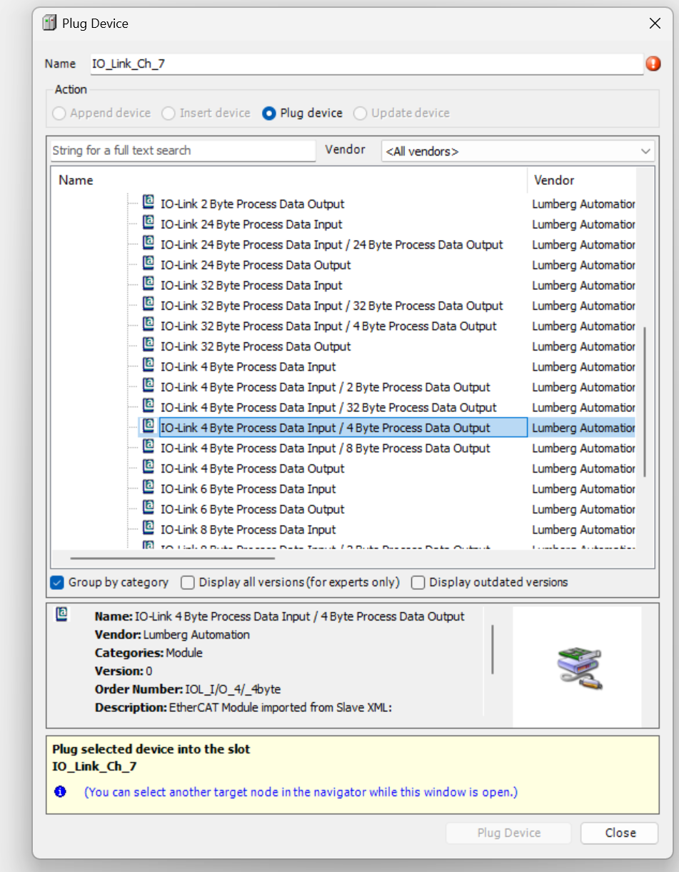
Plug Ch7
Channel 7 is connected to OMRON’s E3AS-HL5000LMN IO-Link device.
Right click on IO_Link_Ch7 > Plug Device.
Add IO-Link 4 Byte Process Data Input/ 4 Byte Process Data Output from Device List.
Download
Finally, Download the Configuration to the CPU.
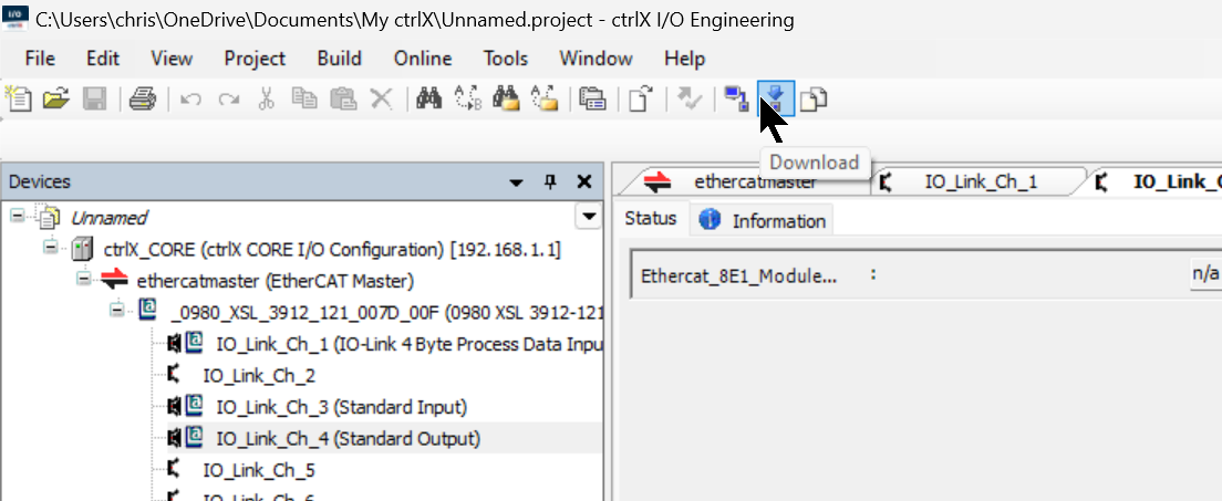
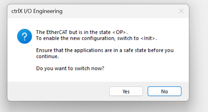
If the EtherCAT Master is already in the OP state, a warning will be displayed – Press Yes to process.
Done!
Check On Web Server
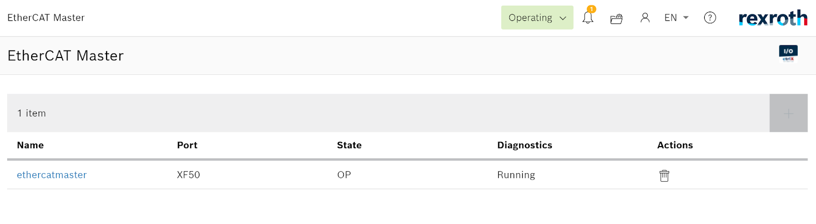
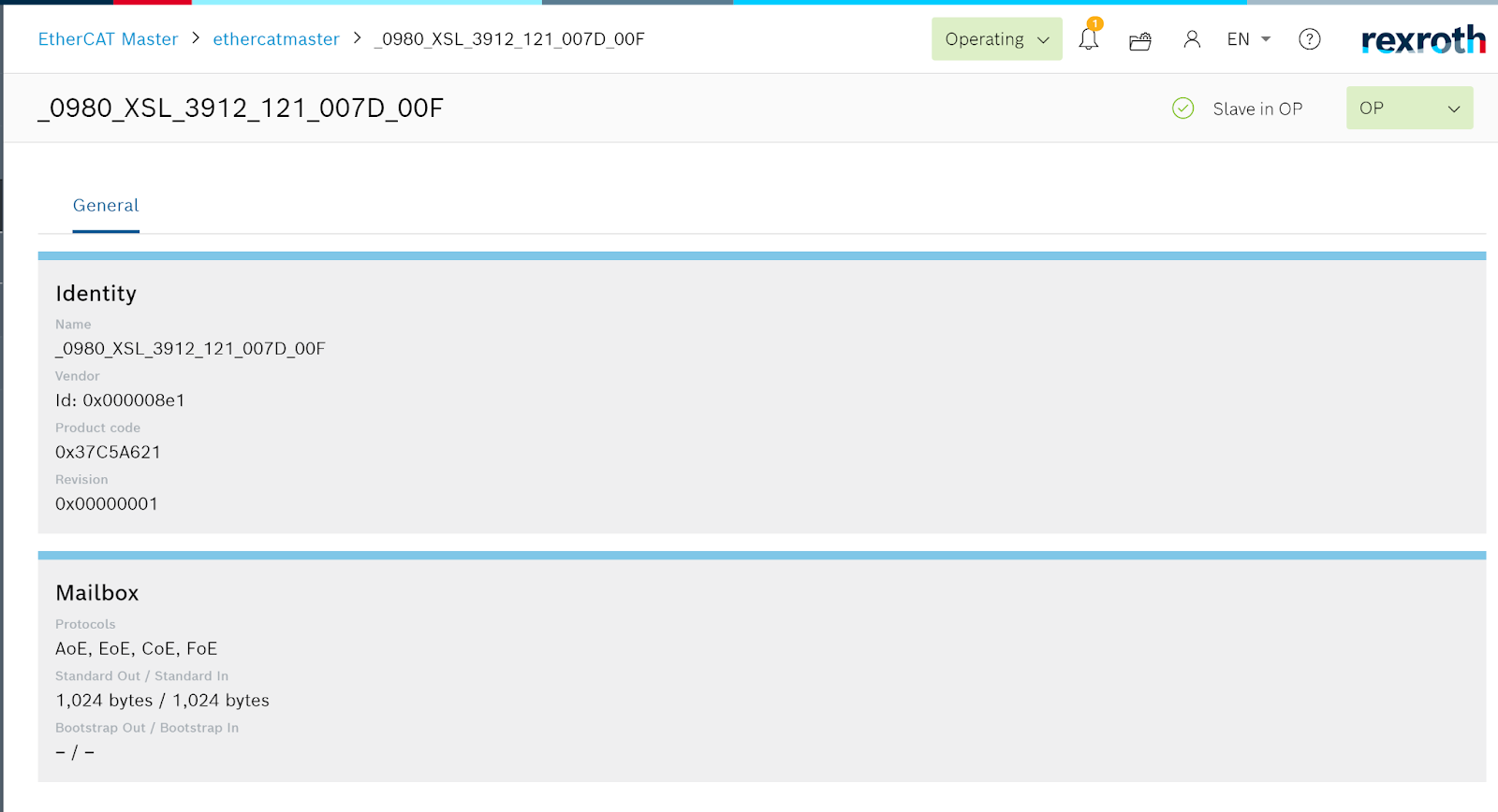
Access the ctrlX Web Server again and check the status of the EtherCAT Master.
Now the EtherCAT State Machine is in the OP state. In other words, the EtherCAT Master is working without problems.
The 0980 XSL 3912-121-007D-00F used in this article also communicates without problems.
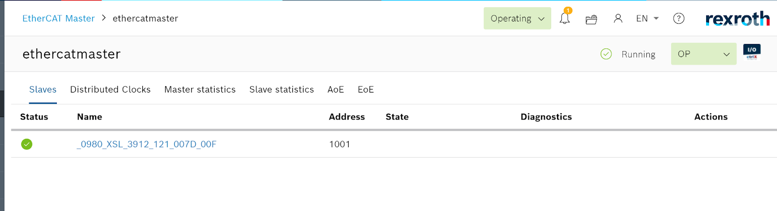
0980 XSL 3912-121-007D-00F is also recognized.
PLC
Click on PLC Enginnering.

Click the “Open ctrlxworks.launcher”.
just a second..
Done!
Data Layer
We want to import the data that is being updated in the EtherCAT Master App with 0980 XSL 3912-121-007D-00F and the cycle in the EtherCAT Master App into the PLC Apps as well, so that’s where DataLayer comes in.
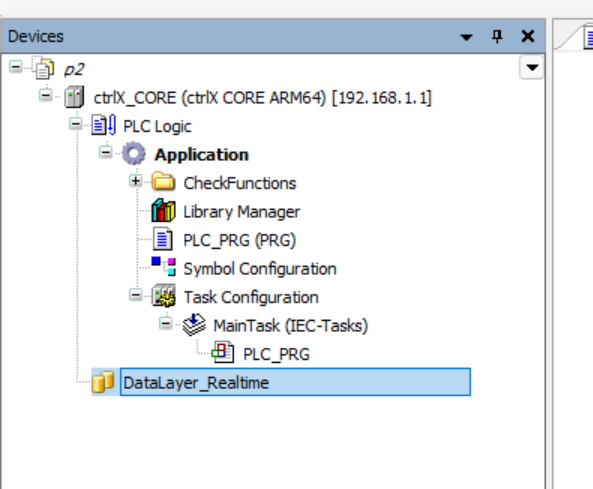
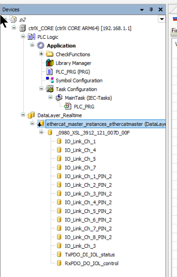
Click on DataLayer_RealTime.
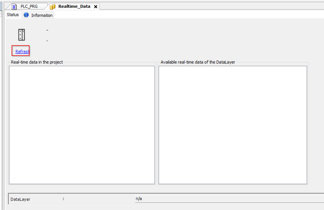
Turn to the DataLayer settings screen and click on the Refresh button.
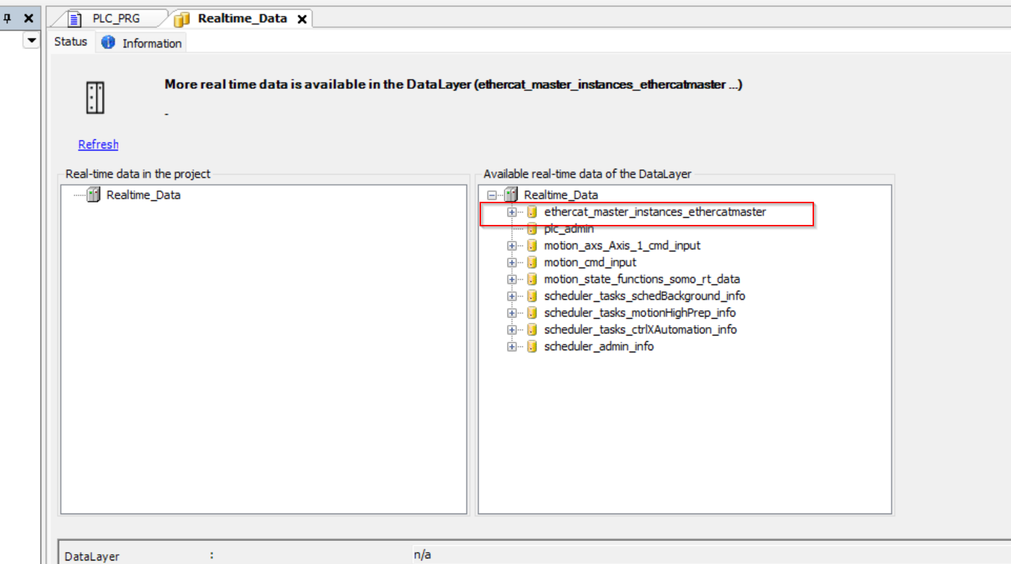
The EtherCAT Master Apps data used in this article was available!
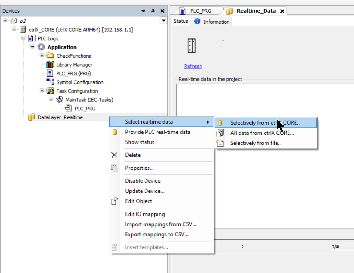
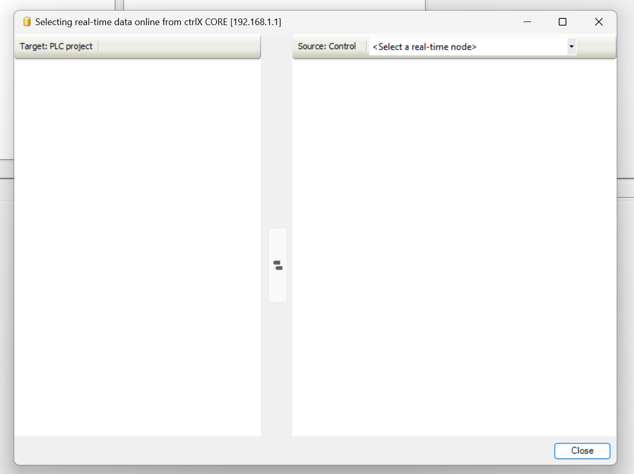
Once you have verified that the EtherCAT Master App data is in the Data Layer, the next step is to add it to the PLC project: DataLayer_Realtime>Right click>Select realtime data>Selectively from Click on ctrlX CORE.
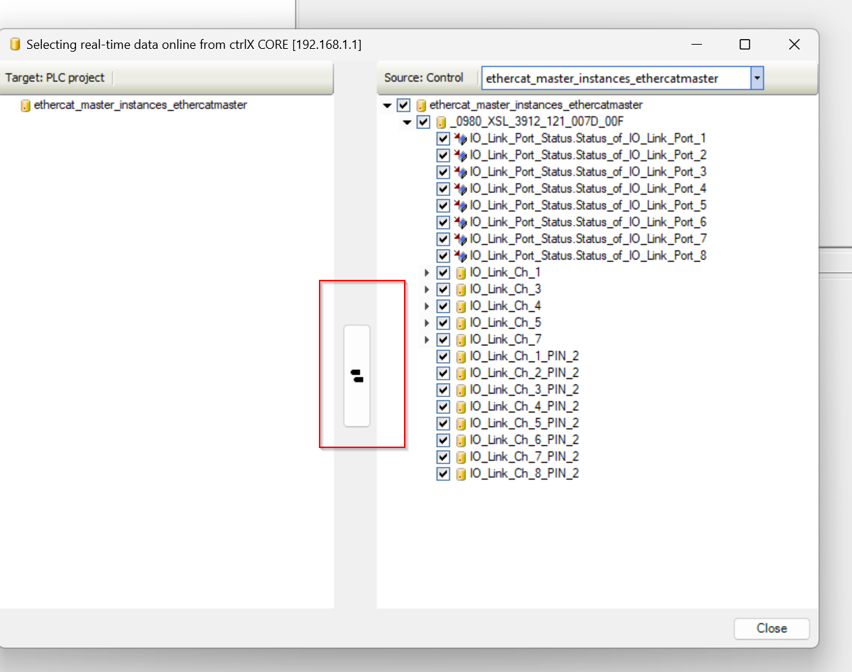
The real-time data selection screen is now displayed.
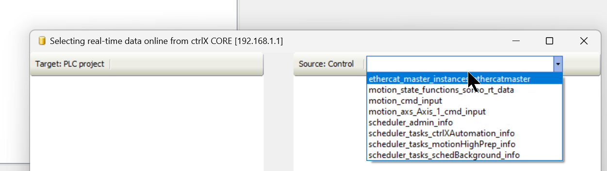
Select ethercat_master_intances_ethercatmaster from Souce:Control on the right.
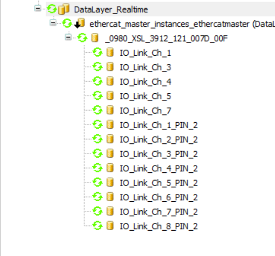
Done!There was also data for 0980 XSL 3912-121-007D-00F.
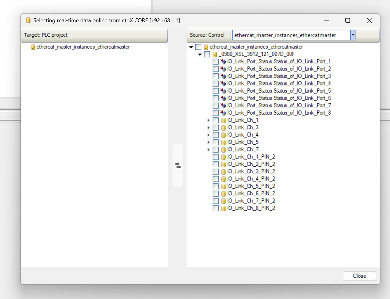
Select all data for 0980 XSL 3912-121-007D-00F.
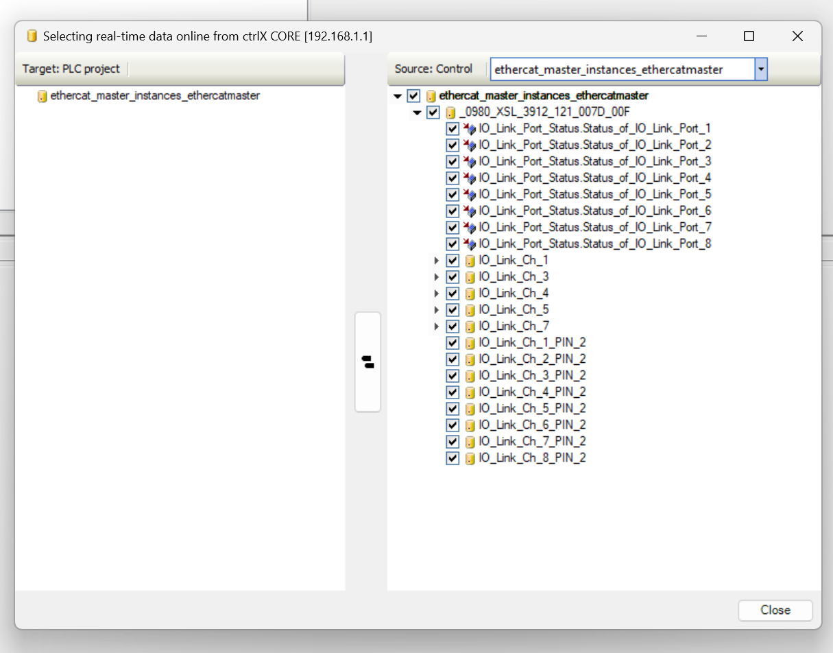
Next, click on the button in the red frame and the selected data will be available in PLC Apps.
Done!
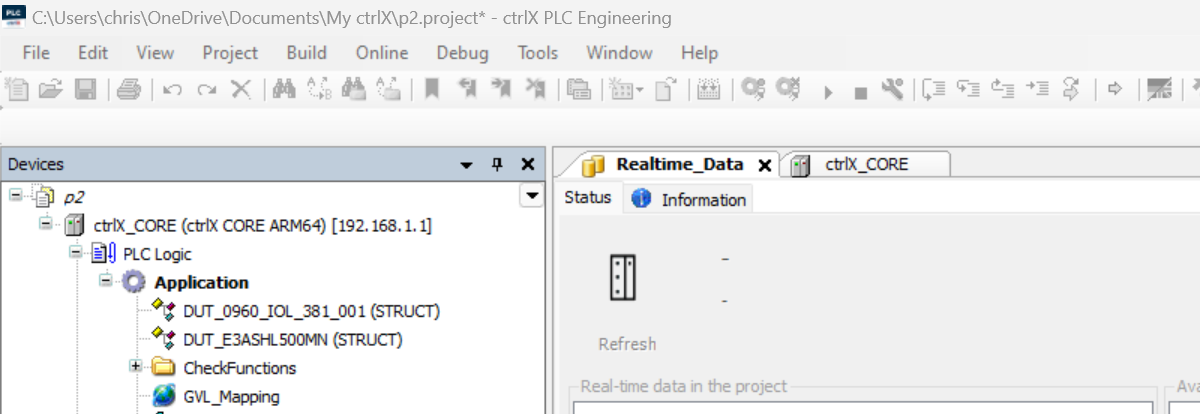
Program
DUT
DUT_0960_IOL_381_001
こちらはIOLink Hubに合わせてたデータ・タイプになります。
| TYPE DUT_0960_IOL_381_001 : STRUCT X1A,X1B,X2A,X2B,X3A,X3B,X4A,X4B ,X5A,X5B,X6A,X6B,X7A,X7B,X8A,X8B:BIT; END_STRUCT END_TYPE |
DUT_E3ASHL500MN
This is the data type to match Omron’s E3ASHL500MN IOLink device.
| TYPE DUT_E3ASHL500MN : STRUCT DetectValueOutput : INT; LightIntensityLevel : USINT; ControlOutput1 :BIT; ControlOutput2 : BIT; InstabilityAlarm:BIT; InsufficinetError:BIT; Warning:BIT; Error :BIT; END_STRUCT END_TYPE |
FunctionBlock
FB_E3ASHL500MN
こちらのFunctionBlockはオムロンのE3ASHL500MN IOLink デバイスのデータを取り出すためのプログラムです。
| FUNCTION_BLOCK FB_E3ASHL500MN VAR_INPUT END_VAR VAR_OUTPUT data:DUT_E3ASHL500MN; END_VAR VAR _raw:ARRAY[0..3]OF BYTE; END_VAR VAR_IN_OUT raw:ARRAY[0..3]OF BYTE; END_VAR _raw:=raw; _raw[0]:=raw[1]; _raw[1]:=raw[0]; MEM.MemMove( pSource:=ADR(_raw) ,pDestination:=ADR(data) ,uiNumberOfBytes:=SIZEOF(raw) ); |
GVL
The GVL here is data that is mapped directly to Process INPUT/OUTPUT data.
| {attribute ‘qualified_only’} VAR_GLOBAL d1 AT %IB12 :ARRAY[0..3]OF BYTE; IOLINK_Hub_1 AT %IB8:DUT_0960_IOL_381_001; IOLINK_Master_DI AT %IB17 :DUT_0960_IOL_381_001; IOLINK_Master_DO AT %QB4 :BYTE; END_VAR |
MAIN
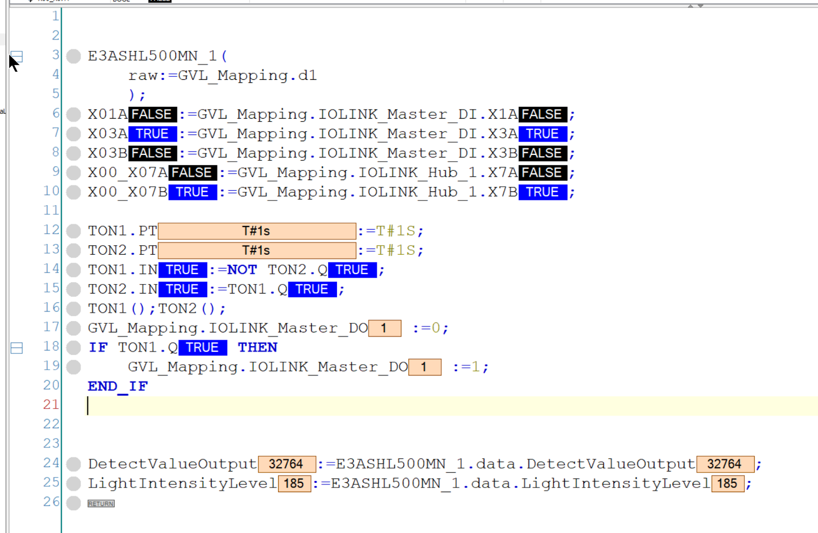
This is the MAIN program, which can read and write digital I/O and IOLINK devices connected to the 0980 XSL 3912-121-007D-00F.
| PROGRAM PLC_PRG VAR E3ASHL500MN_1:FB_E3ASHL500MN; X03A,X03B:BOOL; X00_X01A_,X00_X07A,X00_X07B:BOOL; DetectValueOutput:INT; LightIntensityLevel : USINT; TON1,TON2:TON; END_VAR E3ASHL500MN_1( raw:=GVL_Mapping.d1 ); X00_X01A_:=GVL_Mapping.IOLINK_Hub_1.X1A; X03A:=GVL_Mapping.IOLINK_Master_DI.X3A; X03B:=GVL_Mapping.IOLINK_Master_DI.X3B; X00_X07A:=GVL_Mapping.IOLINK_Hub_1.X7A; X00_X07B:=GVL_Mapping.IOLINK_Hub_1.X7B; TON1.PT:=T#1S; TON2.PT:=T#1S; TON1.IN:=NOT TON2.Q; TON2.IN:=TON1.Q; TON1();TON2(); GVL_Mapping.IOLINK_Master_DO :=0; IF TON1.Q THEN GVL_Mapping.IOLINK_Master_DO :=1; END_IF DetectValueOutput:=E3ASHL500MN_1.data.DetectValueOutput; LightIntensityLevel:=E3ASHL500MN_1.data.LightIntensityLevel; |
Download
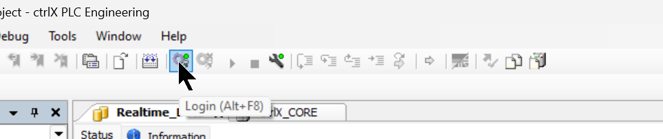
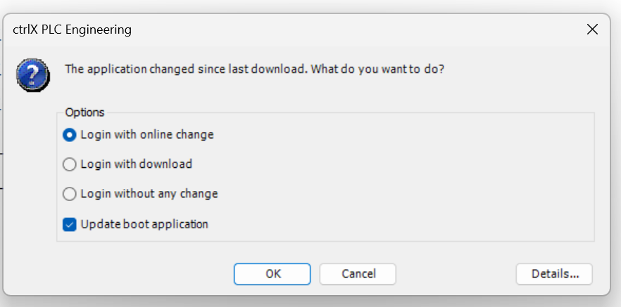
Click the Login button to donwload the project.
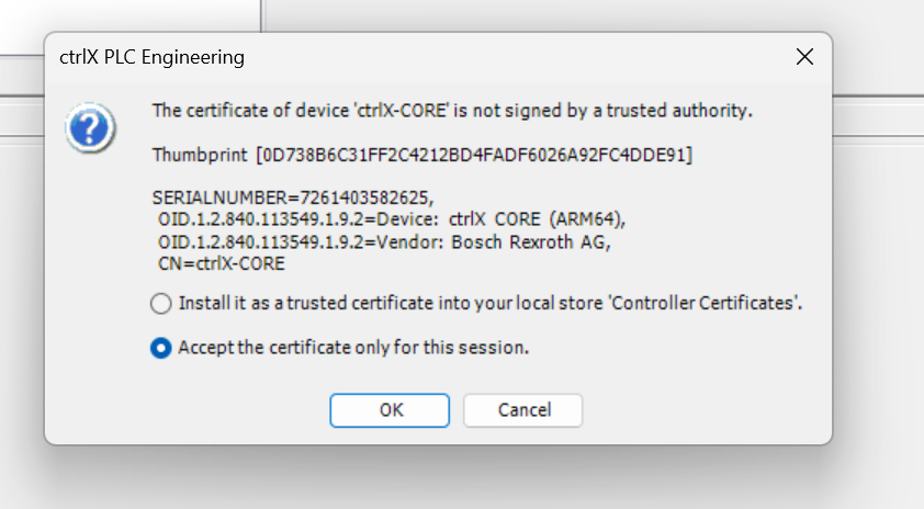
Proceed with Ok.
Result
Done!ctrlX_CROE is now green and PLC Apps is currently running.
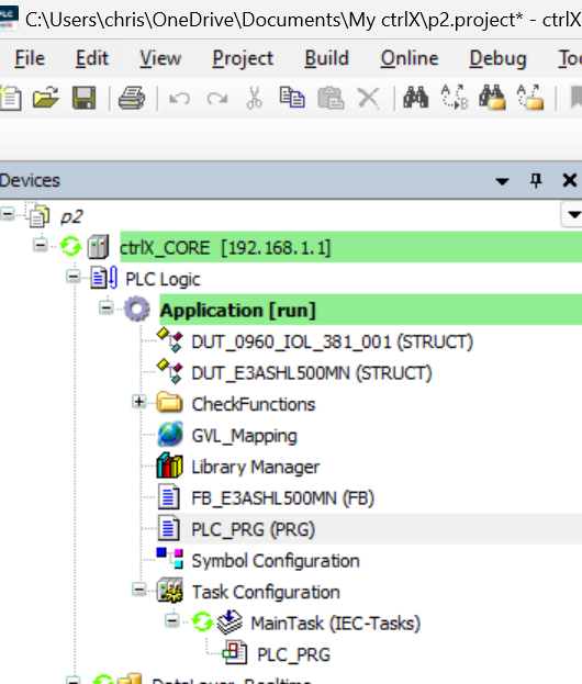
Objects in the DataLayer also have a green ICON, and Nodes in the DataLayer can be accessed normally.
We also took data from the 0980 XSL 3912-121-007D-00F digital I/O and IOLINK devices.
This video shows the operation of issuing an output command from ctrlX to Belden IO Link Master.
ctrlX.Output DO Signal to Belden IOLink Master via EtherCAT App
This is the operation to get the input signal of Belden IO Link Master from ctrlX in this video.
ctrlX.Getting DI Signal From Belden IOLink Master via EtherCAT App
This video shows the operation of getting IOLink device data from ctrlX to Belden IO Link Master.
ctrlX.Getting IOLINK Deivce Data From Belden IOLink Master via EtherCAT App