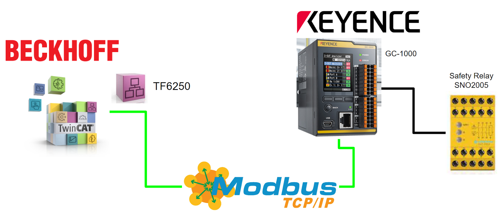
This is the fifth episode of the Keyence Safety Controller Tutorial. This time we will wire up with the Safety relays, start up a Modbus/TCP Server and access various registers from the Beckhoff TwinCAT3 TF6250.
さ、はじめよう!
Reference Video
This is the video Version of the article.
Beckhoff.Modbus TCP/IP connection with Keyence GC1000 Tutorial
Reference Link
http://soup01.com/en/category/keyence/gc-1000-en/
Implementation
Wiring
Before building the project, a brief description of the wiring is first given.
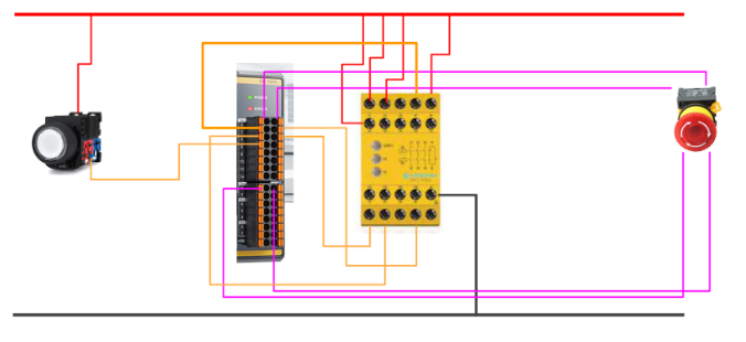
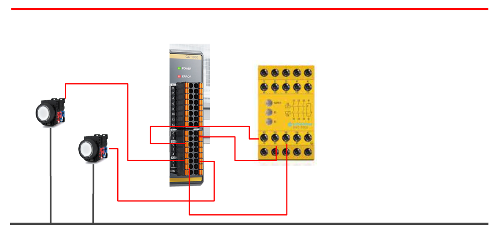
Input
This is the input side wiring of the GC1000, which takes the following input signals from the GC1000:.
- Emergency stop
- NO contact of safety relay
- NC contact of safety relay
- Reset button
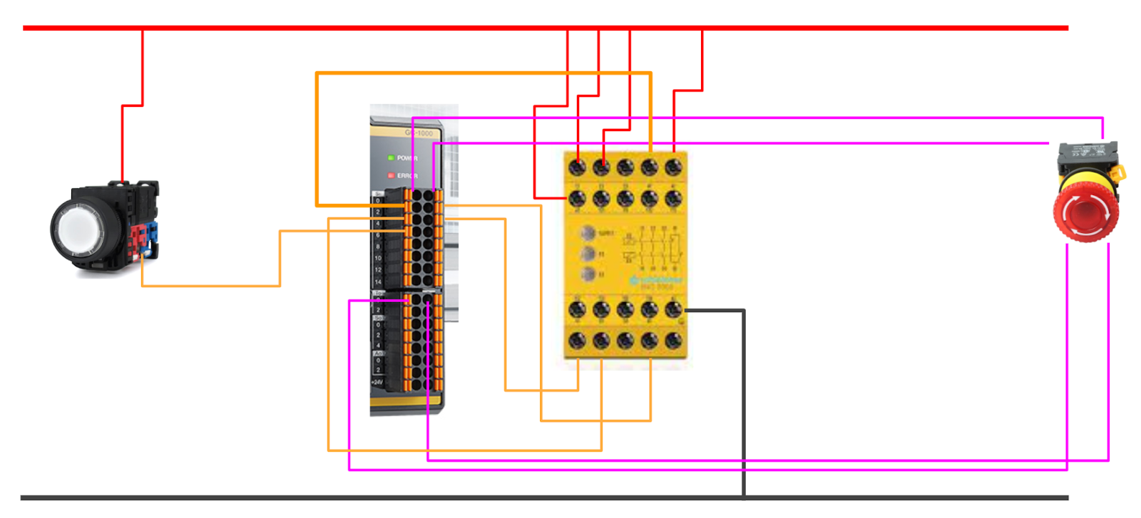
Output
This is the wiring on the output side of the GC1000, taking the following input signals from the GC1000:.
- Coil output of safety relay
- Lamp output when the safety relay is OFF
- Lamp output when safety relay ON
Keyence Side
This article uses the Modbus TCP Server function of the Keyence GC1000 Safety Controller.
Specification
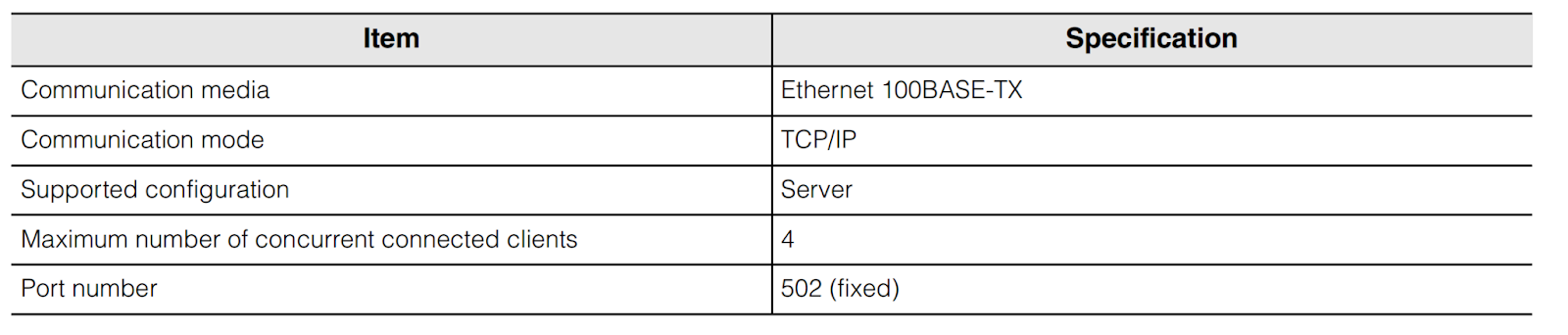
This is the Modbus TCP Server specification for the GC1000, with a fixed Port502 for up to 4 Connections.
Function Code
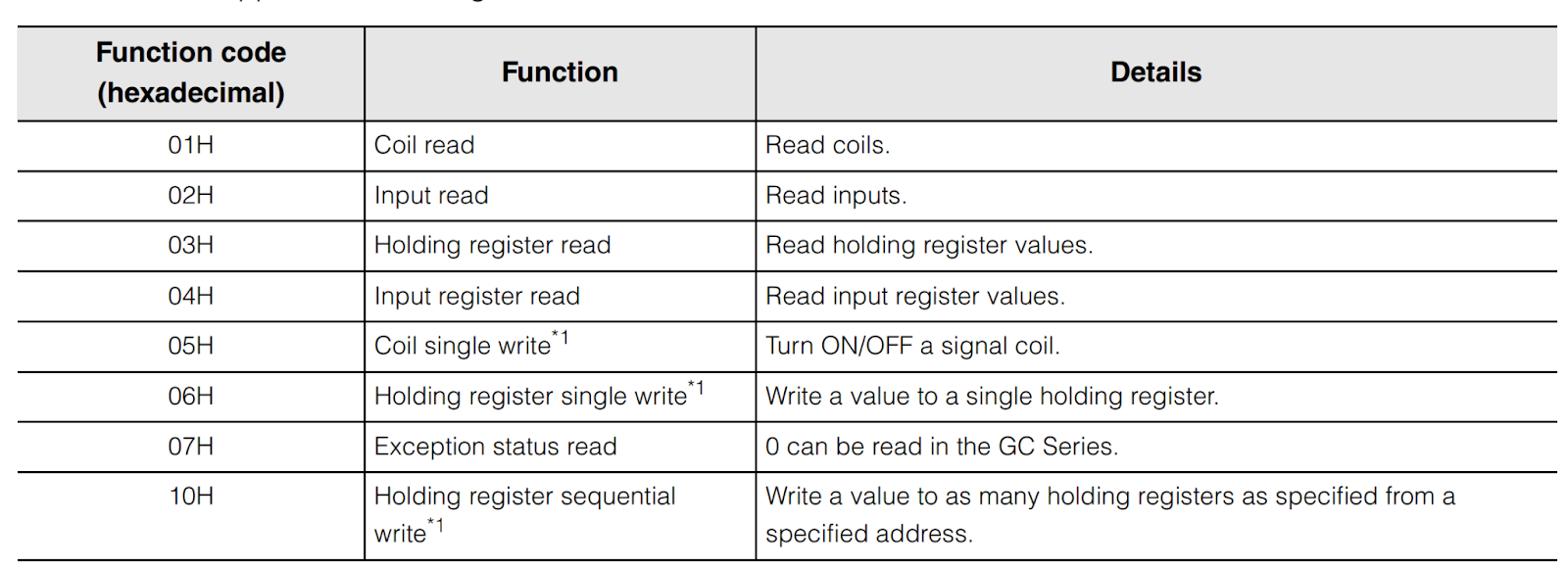
This is the Modbus Function Code supported by the Keyence GC1000 Safety Controller.
Input Register
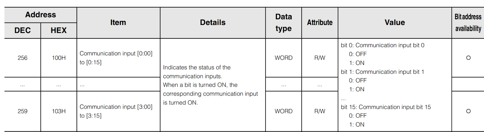
This is the Input Register of the GC1000 used in this article.
Registers 100H to 103H are the GC1000’s Communication Input.
Holding Register
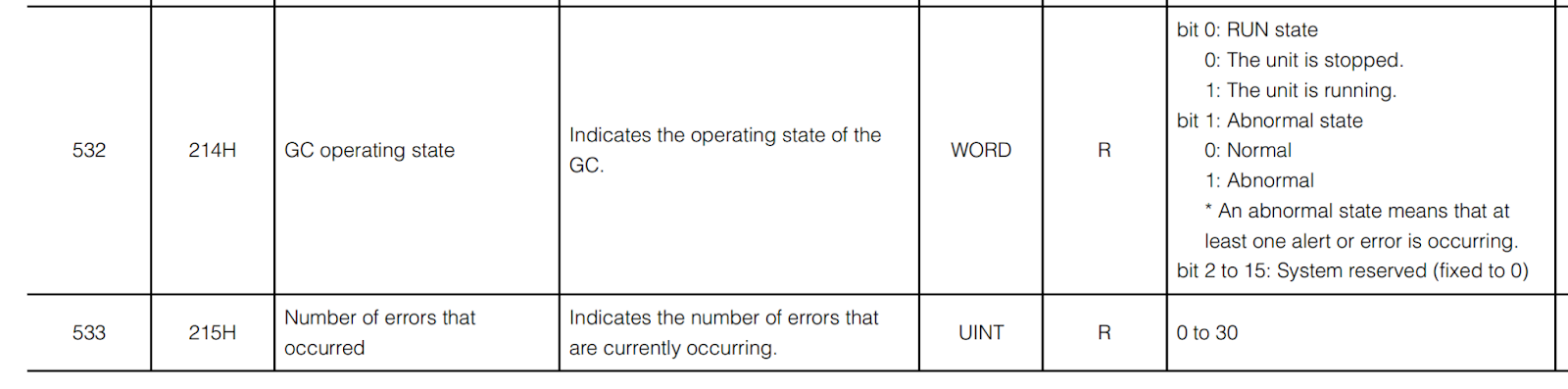
This is the GC1000 HoldingRegister used in this article. Registers 214H to 215H are the GC1000 status and number of error occurrences.
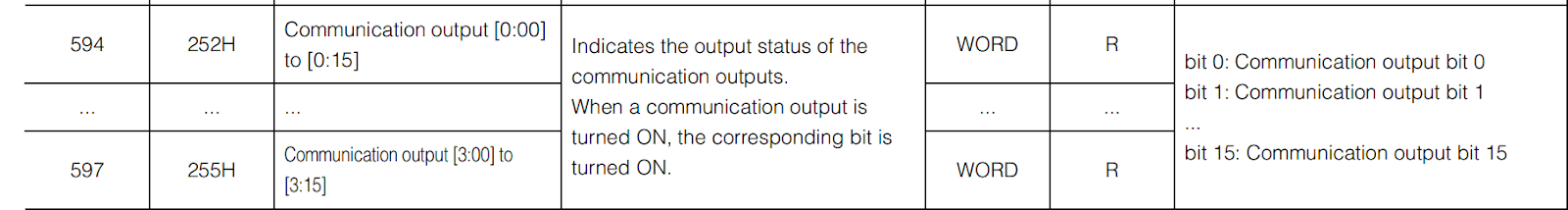
Registers 252H to 255H are the Communication Output of the GC1000.
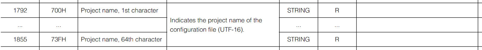
Registers 700H to 73FH are the names of the projects currently being run by GC1000.
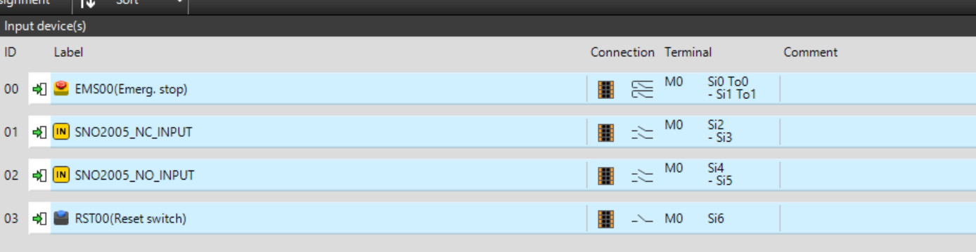
Input Configuration
This is the GC1000 input configuration.
- EMS00: Emergency stop button
- SNO2005_NC_INPUT: B contact for safety relay SNO2005
- SNO2005_NO_INPUT: A contact for safety relay SNO2005
- RST000: Reset button
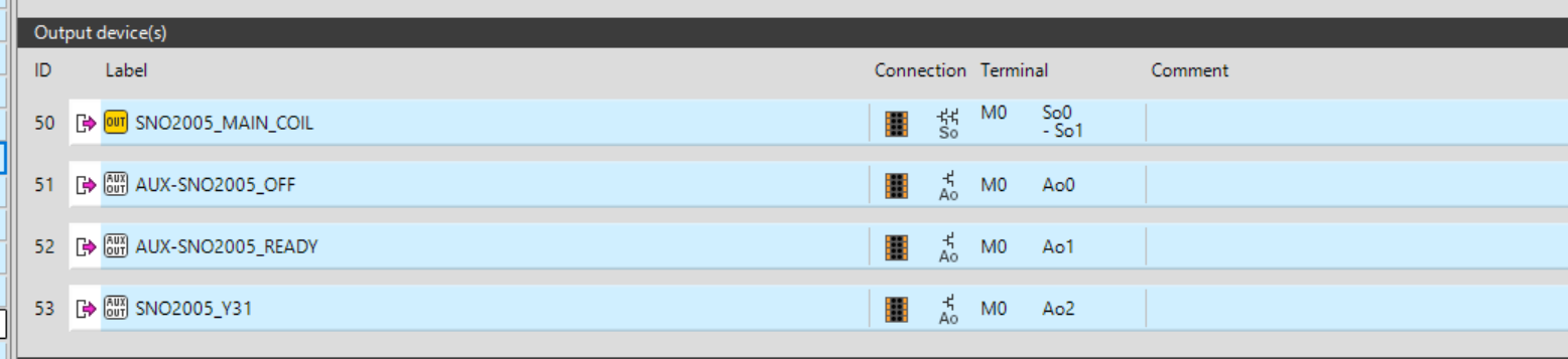
Output Configuration
This is the output configuration of the GC1000.
- SNO2005_MAIN_COIL: Coil of safety relay SN2005
- AUX-SNO2005_OFF: Lamp output indicating that the coil of the safety relay SNO2005 is currently OFF
- AUX-SNO2005_READY: Lamp output indicating that the coil of the safety relay SNO2005 is currently ON
- SNO2005_V31: on coil per KM of safety relay SN2005
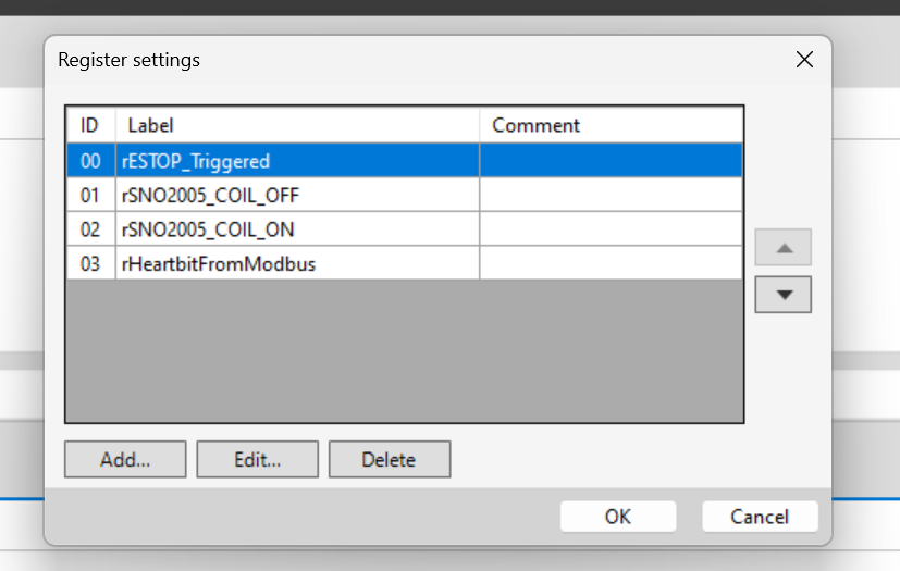
Register Configuration
This article also uses the internal registers of the GC1000.
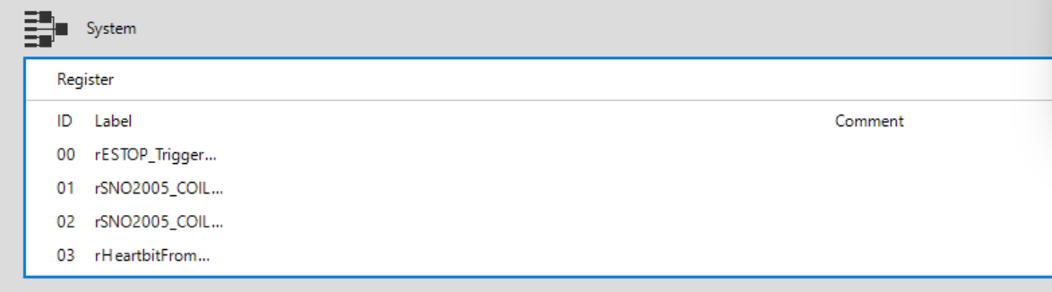
There are four Registers in the project, which are the state of the emergency stop, the state of the safety relay and the Life bit of Modbus. c
Program
The programme is divided into two pages.
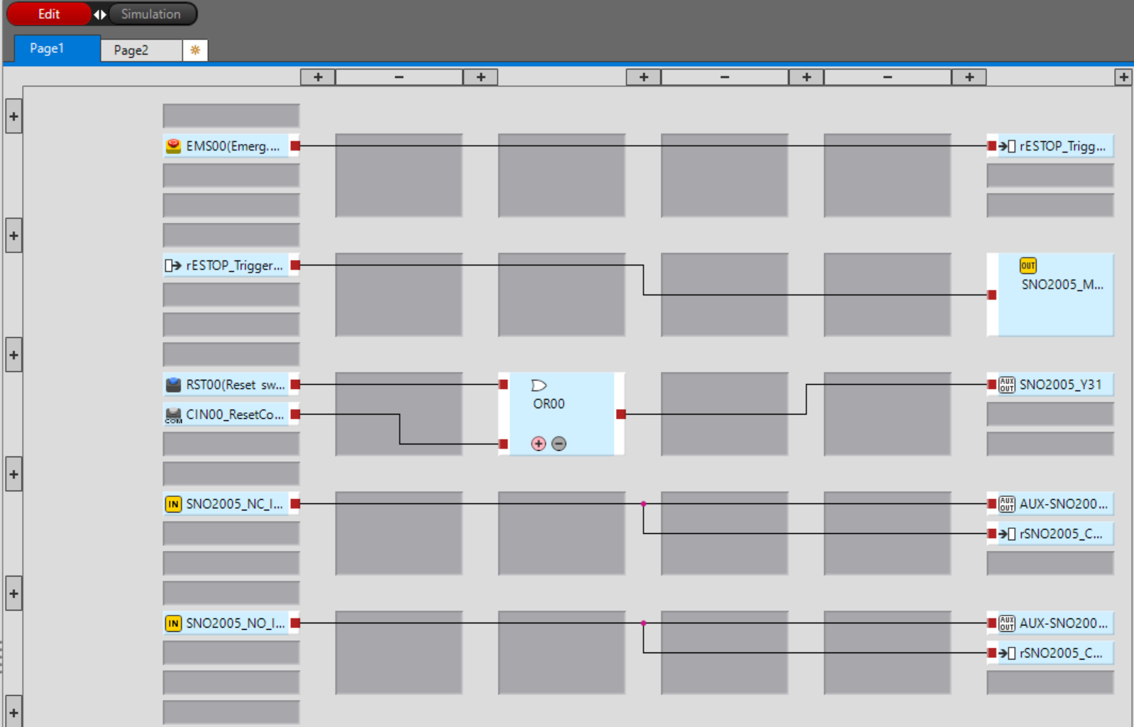
Page1
Page 1 is the programme for the main control and data output to internal registers.
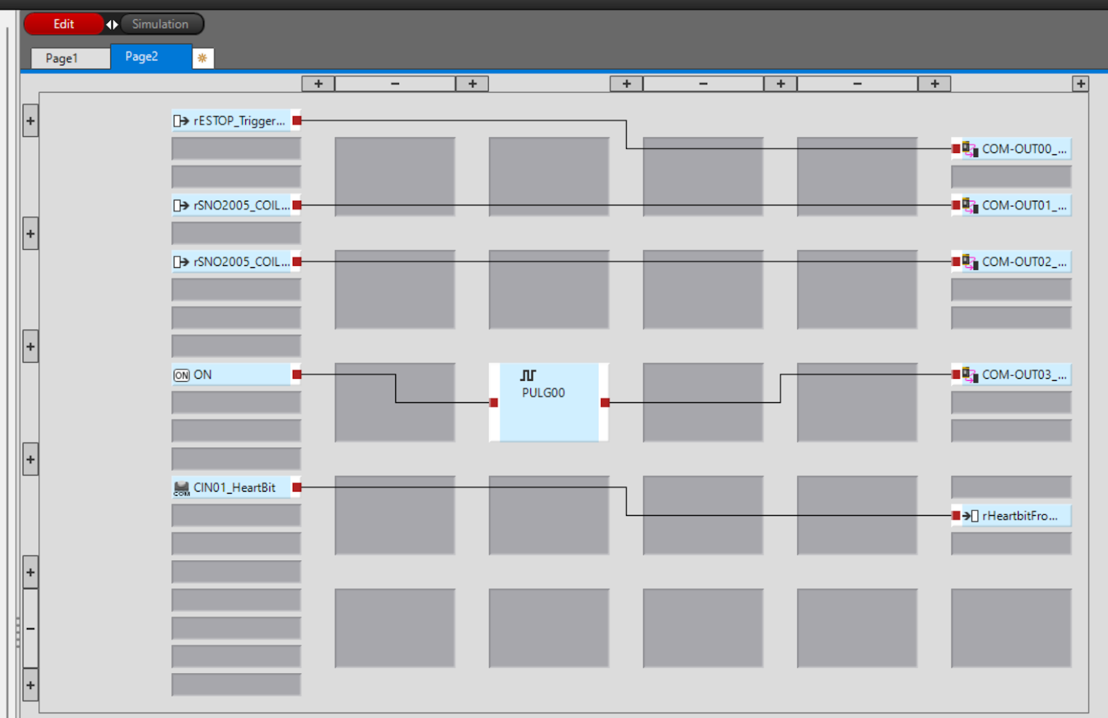
Page2
Page 2 is a program to pass the status of the GC1000 to the communication output.
ModbusTCP/IP Configuration
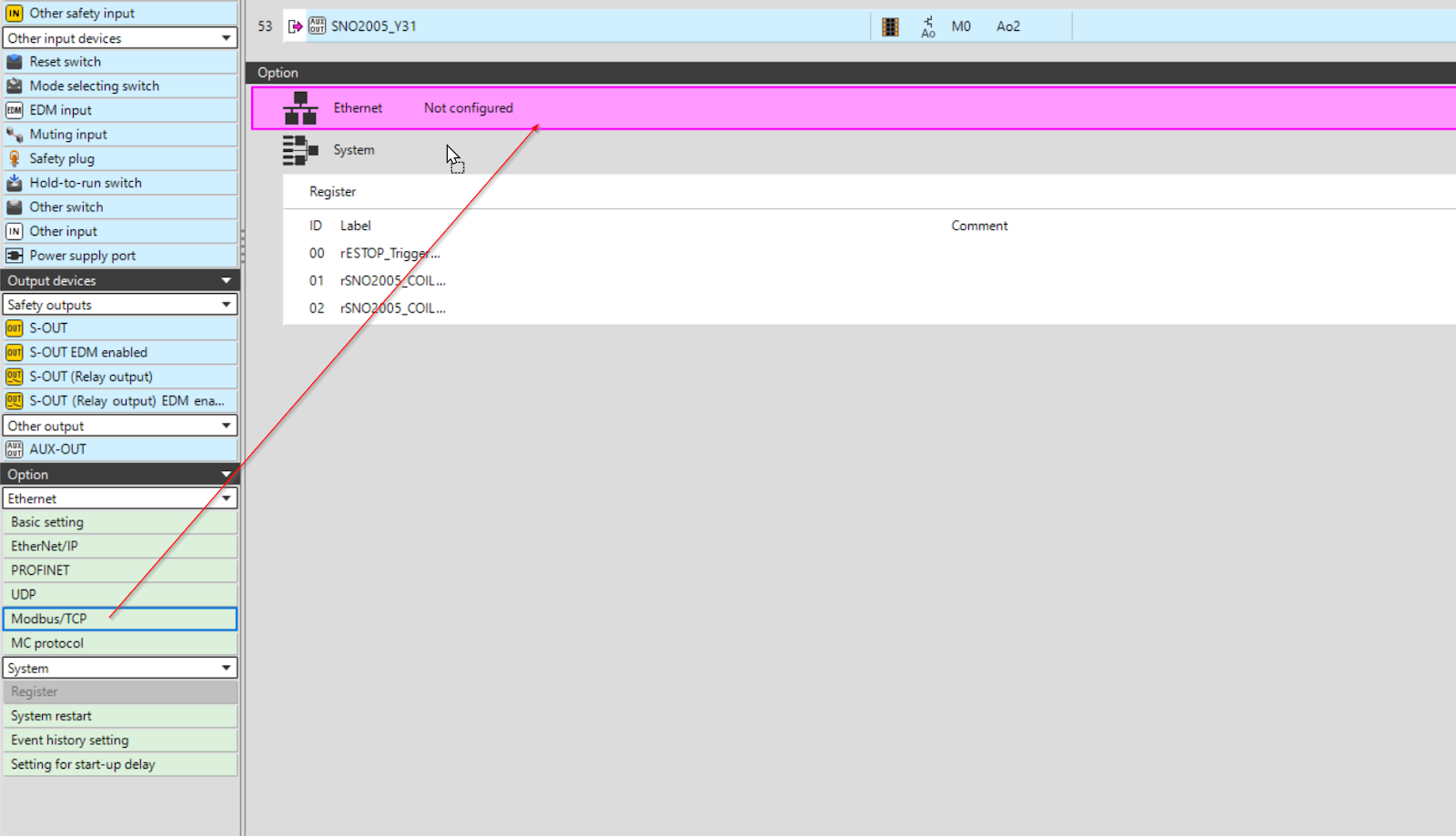
The next step is to configure the Modbus TCP/IP settings for the GC1000.
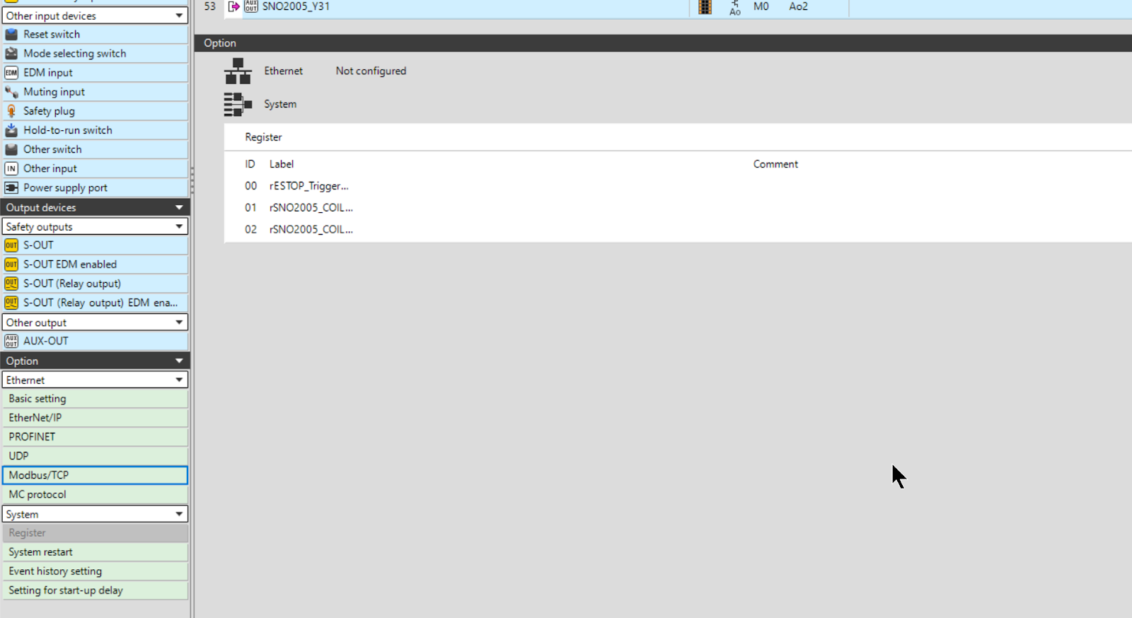
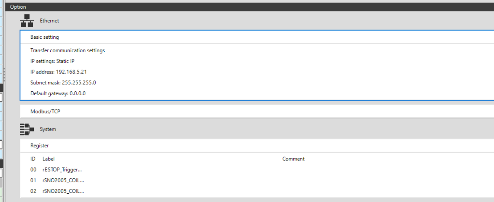
Add ModbusTCP to the Ethernet Field from the GC Configurator.
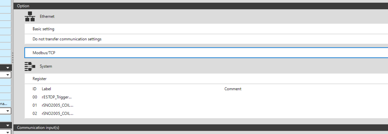
Done!Modbus TCP/IP Driver has been added.
Ethernet Setting
Next, click on Basic Setting to configure the Ethernet settings.
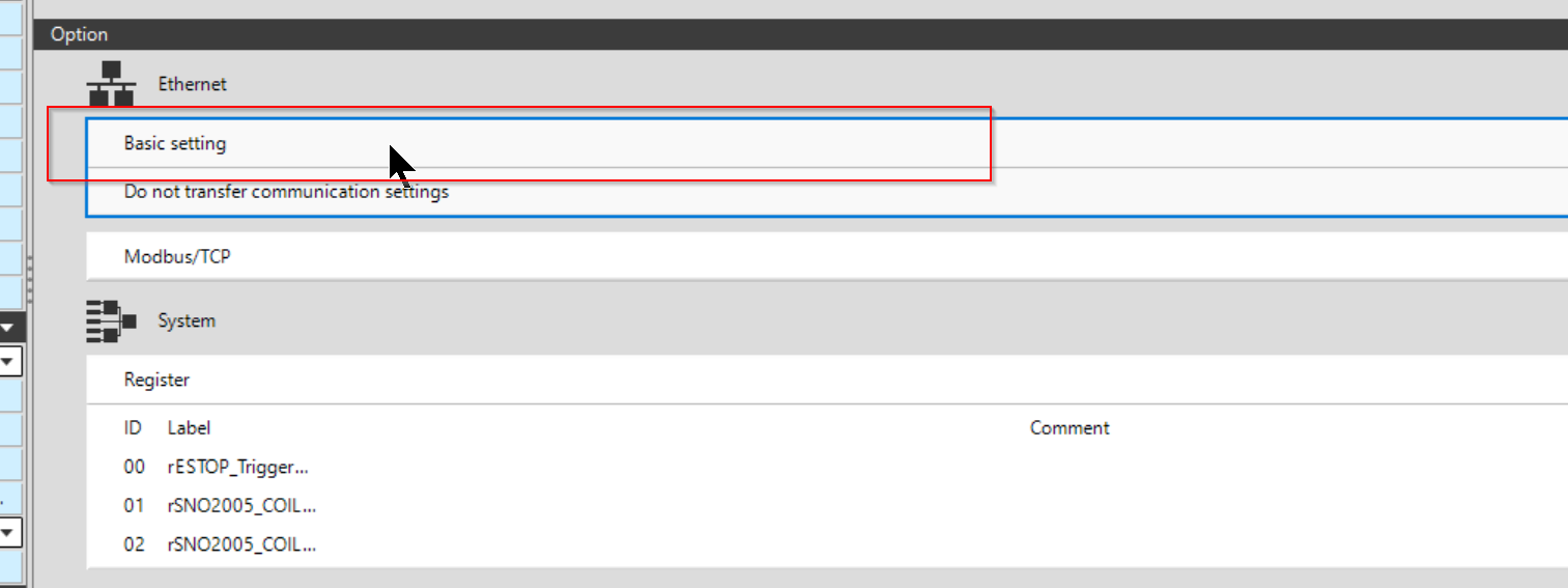
The Basic Setting screen for Ethernet appears.
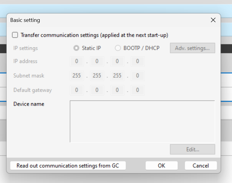
Checkbox under Transfer communication settings and select Static IP.Next, you need to set the IP address. You will transfer the IP settings of your project to the GC1000.
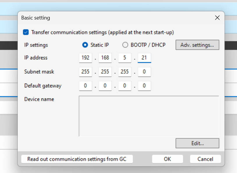
Done!
Beckhoff Side
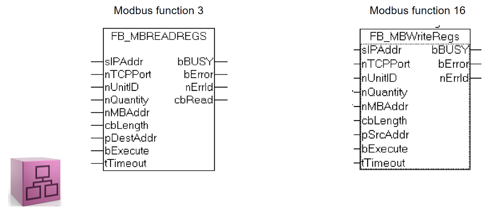
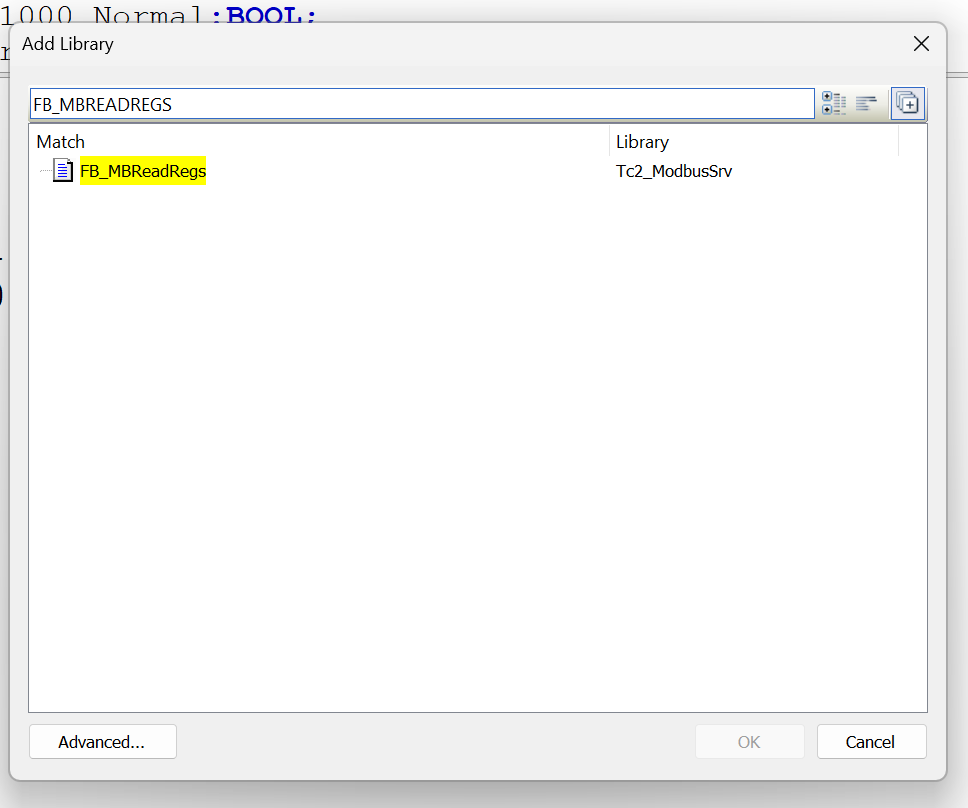
The next section describes the implementation on the Beckhoff TwinCAT side. This time, the FBs FB_MBREADREGS and FB_MBWriteRegs in the TF6250 are used to access the GC1000 registers.
Install TF6250
Download and install the TF6250 Setup File from the Link below.
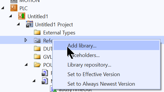
Add library
Please add the modbus library to your project.
Program
FC_ClearArray
This function clears the array value to zero.
| FUNCTION FC_ClearArray VAR_IN_OUT io:ARRAY[*]OF WORD; END_VAR VAR i:DINT; END_VAR FOR i:=LOWER_BOUND(io,1) TO UPPER_BOUND(io,1) DO io[i]:=16#0; END_FOR |
MAIN
This is the MAIN Program.
| PROGRAM MAIN VAR //Function Block _MBRead:FB_MBReadInputRegs; _MBWrite:FB_MBWriteRegs; //Buffer ReadBuffer:ARRAY[0..99]OF WORD; WriteBuffer:ARRAY[0..99]OF WORD; //Data From GC1000 ProjectName :WSTRING; GC1000_Running,GC1000_Normal:BOOL; GC1000_NumberOfError:WORD; EStopTriggered,SNO2005_CoilOFF,SNO2005_CoilON:BOOL; //Command to GC1000 bReset:BOOL; //Program Flow Control iStep:INT; TON1,TON2,TON3:TON; END_VAR aInit();aReadDataFromGC1000();aWriteData2GC1000();aBusyTimeOut(); |
ACTION:aBusyTimeOut
The Action here is to set the timeout for receiving in the Input Register.
| //Busy Timeout TON3(in:=_MBRead.bBusy ); IF TON3.Q THEN iStep:=0; END_IF |
ACTION:aInit
The Action here initialises the timer setting values, etc.
| TON1.PT:=T#1S; TON2.PT:=T#1S; TON3.PT:=T#5S; TON1(IN:=NOT TON2.Q); TON2(in:=TON1.Q); |
ACTION:aReadDataFromGC1000
This Action here reads each Input Register to GC1000 using CASE minutes.
| //Read Process CASE iStep OF 0: _MBRead.sIPAddr:=’192.168.5.21′; _MBRead.nTCPPort:=502; _MBRead.nUnitID:=1; _MBRead.cbLength:=SIZEOF(ReadBuffer); _MBRead.pDestAddr:=ADR(ReadBuffer); _MBWrite.sIPAddr:=’192.168.5.21′; _MBWrite.nTCPPort:=502; _MBWrite.nUnitID:=1; _MBWrite.cbLength:=SIZEOF(WriteBuffer); _MBWrite.pSrcAddr:=ADR(WriteBuffer); _MBRead(bExecute:=FALSE); EStopTriggered:=FALSE; SNO2005_CoilOFF:=FALSE; SNO2005_CoilON:=FALSE; ProjectName:=” “; iStep:=10; 10: _MBRead.nMBAddr:=16#252; _MBRead.nQuantity:=4; _MBRead(bExecute:=TRUE); IF _MBRead.cbRead <> 0 OR _MBRead.bError THEN _MBRead(bExecute:=FALSE); IF _MBRead.cbLength <> 0 THEN EStopTriggered:=ReadBuffer[0].0; SNO2005_CoilOFF:=ReadBuffer[0].1; SNO2005_CoilON:=ReadBuffer[0].2; iStep:=20; END_IF; IF _MBRead.bError THEN iStep:=900; END_IF END_IF 20: IF NOT _MBRead.bBusy THEN FC_ClearArray(io:=ReadBuffer); iStep:=30; END_IF 30: _MBRead.nMBAddr:=16#700; _MBRead.nQuantity:=64; _MBRead(bExecute:=TRUE); IF _MBRead.cbRead <> 0 OR _MBRead.bError THEN _MBRead(bExecute:=FALSE); IF _MBRead.cbLength <> 0 THEN MEMMOVE( destAddr:=ADR(ProjectName) ,srcAddr:=ADR(ReadBuffer) ,n:=64*2 ); iStep:=40; END_IF; IF _MBRead.bError THEN iStep:=901; END_IF END_IF 40: IF NOT _MBRead.bBusy THEN FC_ClearArray(io:=ReadBuffer); iStep:=10; END_IF 50: _MBRead.nMBAddr:=16#214; _MBRead.nQuantity:=2; _MBRead(bExecute:=TRUE); IF _MBRead.cbRead <> 0 OR _MBRead.bError THEN _MBRead(bExecute:=FALSE); IF _MBRead.cbLength <> 0 THEN GC1000_Running:=ReadBuffer[0].0; GC1000_Normal:=NOT ReadBuffer[0].1; GC1000_NumberOfError:=ReadBuffer[1]; iStep:=60; END_IF; IF _MBRead.bError THEN iStep:=902; END_IF END_IF 60: IF NOT _MBRead.bBusy THEN FC_ClearArray(io:=ReadBuffer); iStep:=10; END_IF 900,901,902: iStep:=0; END_CASE |
ACTION:aWriteData2GC1000
This Action here writes the reset signal and heartbeat to the Holding Register of the GC1000.
| WriteBuffer[0].0:=bReset; WriteBuffer[0].1:=TON1.Q; //Write Process //100=Communication Input _MBWrite( nMBAddr:=16#100 ,nQuantity:=4 ,bExecute:=NOT _MBWrite.bBusy ); |
Result
This video shows the Beckhoff TwinCAT3 writing a Keyence GC1000 register via the TF6250.
Keyence.Write GC1000 Register via TwinCAT TF6250 ModbusTCP
This video shows the operation of a Beckhoff TwinCAT3 reading Keyence GC1000 registers via TF6250.