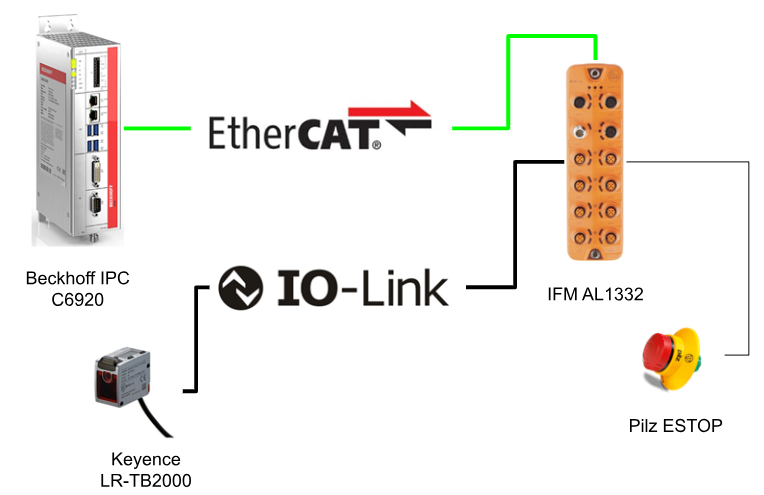
In this article, the Beckhoff IPC C6920 is connected to the IFM AL1332 Ethercat IO-LINK Master ,to obtain the current distance from the Keyence IO-LINK Distance Sensor LR-TB200 ,and the Pilz ESTOP is also wired to the IFM AL1332 Port for Simple control of DI/DO.
Let’s start!
Thanks!
This article was made possible thanks to Beckhoff Automation K.K., Beckhoff’s Japanese subsidiary, and ifm efector co. ltd. for lending us their equipment. Thank you very much.
ベッコフ日本法人ベッコフオートメーション株式会社
IPC6920-005 was lent to us by Beckhoff Automation Japan K.K. Beckhoff Automation was founded in 1980 and is a German company at the forefront of the introduction of open automation systems based on PC-based control technology.
Beckhoff Automation K.K., the Japanese subsidiary of Beckhoff, established its head office in Yokohama in 2011 and its Nagoya office in 2017.

This is the homepage of Beckhoff Automation K.K., Beckhoff’s Japanese subsidiary.
Best regards.
https://www.beckhoff.com/ja-jp/
ifm efector co. ltd.
ifm was founded in Germany in 1969 as a sensor specialist with the company philosophy “ifm-Close to you”. Today ifm is a large company with more than 7,000 employees in over 95 countries and is widely recognised worldwide as a pioneer in IO-Link, the key to the IoT.

This is the homepage of IFM.
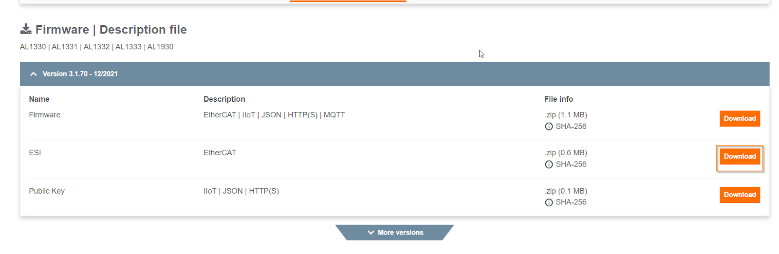
Download ESI File
Ports
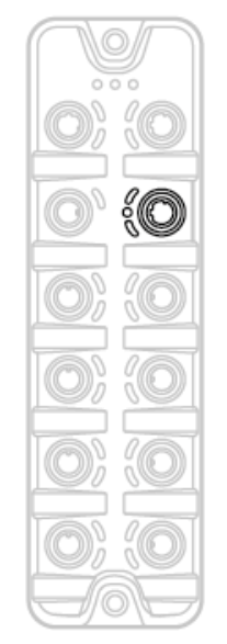
EtherCAT
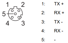
This is an EtherCAT Port.
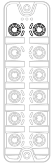
The Connector is M12 and the following is the Port arrangement.
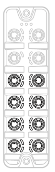
IOT
This is the IOT Port and we will show you how to use it again in the next article.
The Connector is M12 and the following is the Port arrangement.
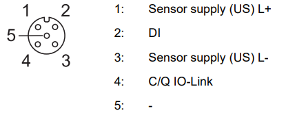
IOLINK Port
This is the IOLINK Port.
The Connector is M12 and the following is the Port arrangement.
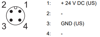
Power
This is a Power Port.
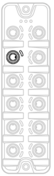
The Connector is M12 and the following is the Port arrangement.
Implementation
IFM Side
First, determine the role of each Port on the IFM Ethercat IO LINK Master. Now Por1, Port 7 is IOLink, Ports 2, 3 and 4 are unused, Port 5 is digital output and Port 6 is digital input.
There are four Operation Modes from IO Ports X1 to X8.
- Disabled: Pin 4 (C/Q) does not exchange data.
- Digital Input (DI): Pin4 (C/Q) receives Binary input data.
- Digital Output (DQ): Pin4 (C/Q) receives Binary output data.
- IO-LINK: Pin 4 (C/Q) exchanges IO-Link data
And Data Mapping has TxPDO and RxPDO, where TxPDO is Bytes input data and RxPDO is Bytes output data from the Ethercat Master.
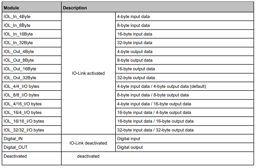
Support Module
The following modules are supported by AL1332.
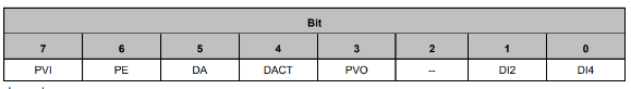
Port Qualifier(0xF101)
| DI4 | True = PIN4 is on. |
| DI2 | True = PIN2 is on. |
| PVO | True=IOLINK device data valid. |
| DACT | True=Port cannot be disabled or used. |
| DA | True=IOLINK De Beers in Pre Operate or Operate state. |
| PE | True=Port error. |
| PVI | True=Port data is valid. |
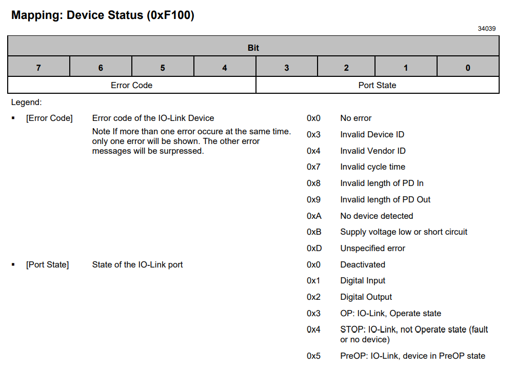
Device Status(0xF100)
Keneyce Side
Setup
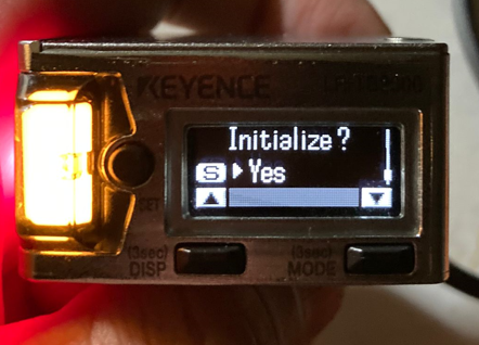
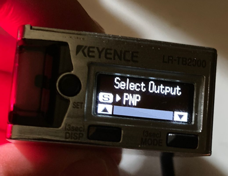
This section briefly describes the configuration procedure for Keyence’s LR-TB2000 Sensor: press and hold Mode+Set Button to initialise the device.
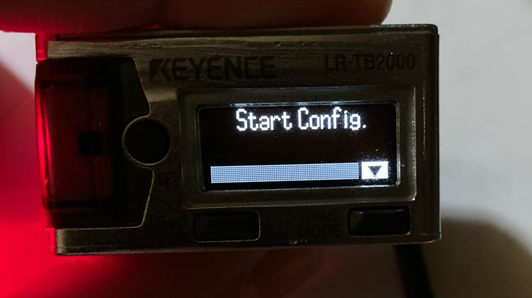
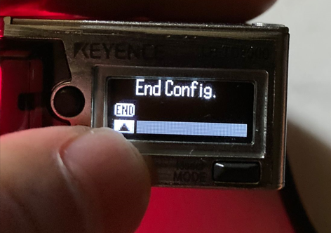
Start Config. is displayed; press the MODE button to proceed.
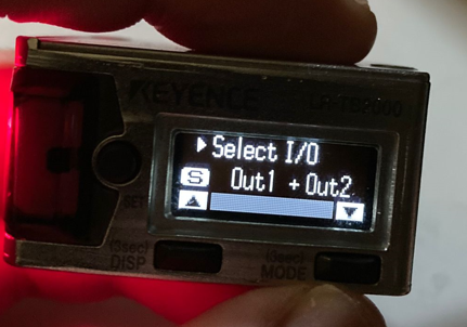
Select I/O is displayed and the MODE proceeds with the Default setting of Out1+Out2 this time.
Set Output Mode to PNP and proceed with MODE.
Done!
Mapping
The distance Sensor can figure is 49-9999.

Beckhoff Side
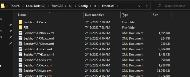
Import the ESI File
Unzip the Zip and move all the Files inside to \TwinCAT3\3.1\Config\io\EtherCAT.
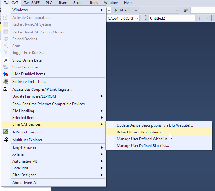
Update the Device List under TwinCAT>EtherCAT Devices>Reload Device Descriptiona.
Add EtherCAT Master
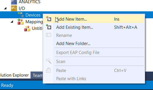
Add an EtherCAT Master, e.g. I/O>Device>Add New Item.
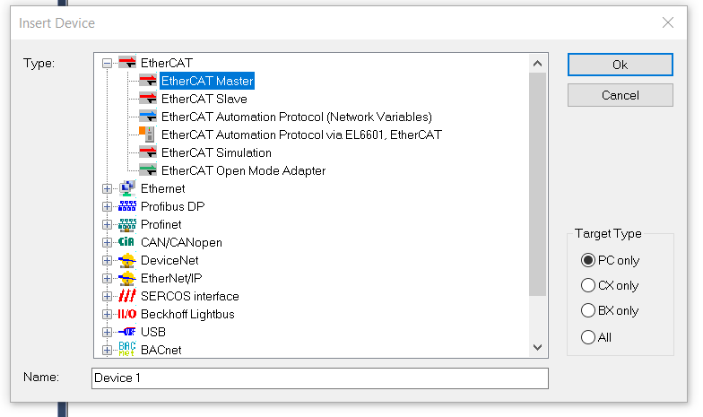
Select EtherCAT>EtherCAT Master>Ok.
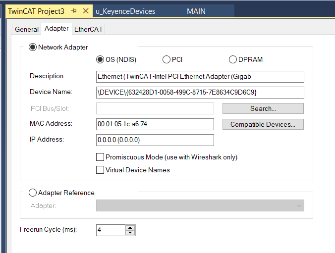
Recheck whether you have selected the correct Interface from the Adapter Tab.
Add IFM AL1332
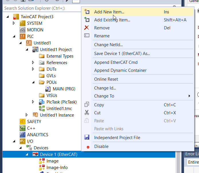
Next, add the IFM Ethercat IO LINK Master AL1332, EtherCAT>Add New Item.
Select Ifm IO-Link master AL1332 >Ok.
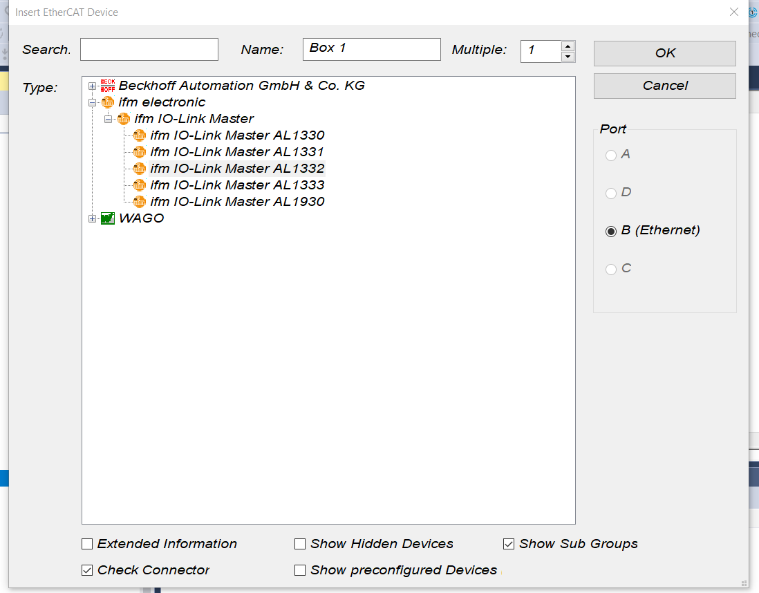
IFM AL1332 has been added.

Configure IFM
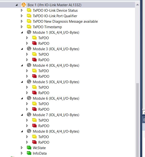
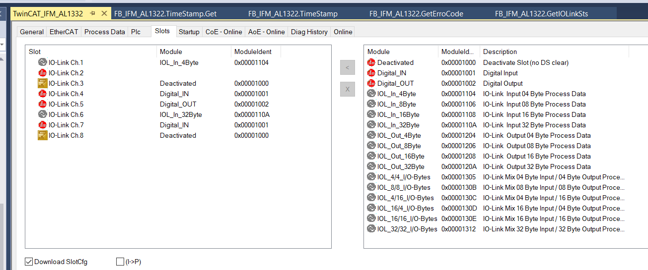
The next step is to change the settings of the IFM AL1332 from the TwinCAT IDE – by default all ports are also set to IOLINK 4IN/4OUT. First click on “Box 1”.
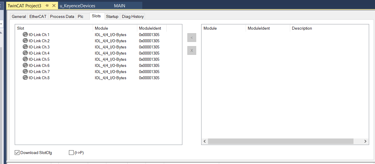
Configure the settings for each Port in the Slots Tab.
For example, if you select IO-Link Ch2 and click on the “x” button, the current Port setting for Ch2 will be deleted.
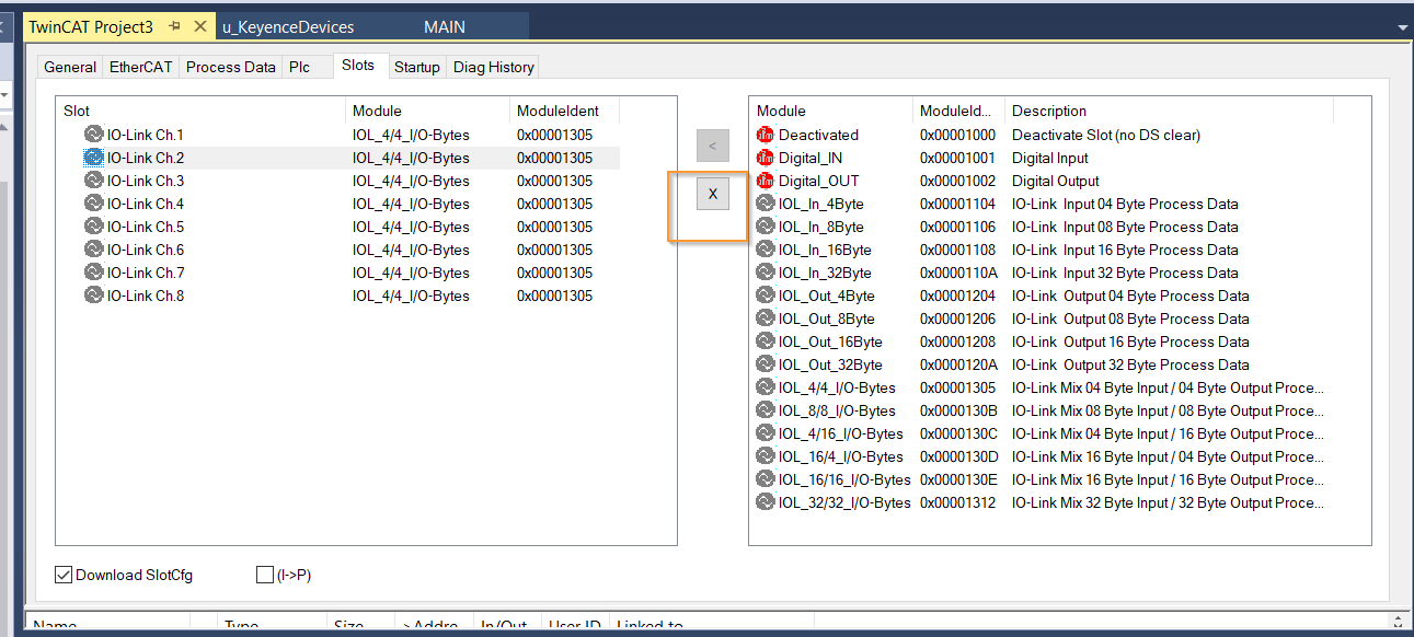
Now Ch2 has nothing in the Module column. But if you compile it as it is, you get an Error.
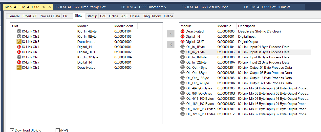
Next, select IOL_in_4_Byte from the Module List on the right and add the Module to Ch2 with the “>” Button.
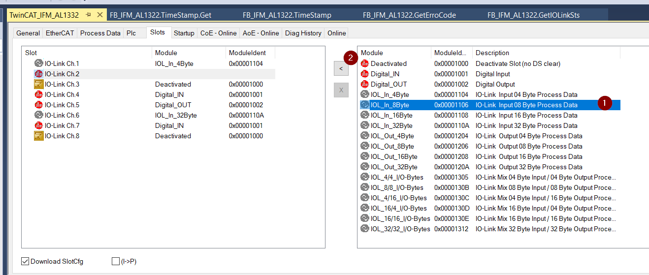
Now CH2 is set to receive IOL_in_4_Byte, i.e. 4 Bytes of INPUT data via IO-LINK.
Set up each Port as shown in the diagram on the IFM Side,reference from the configuration.
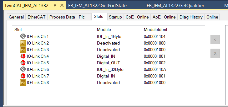
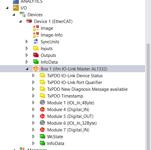
From the perspective of the Tree in Box 1, the Configuration of each Port is also reflected and disabled Ports are not displayed.
Program
DUT
DUT_PortState
This is a DUT showing the status of each Port of the IFM AL1332.
| TYPE DUT_PortState : STRUCT Deactivated :BOOL; DigitalInput :BOOL; DigitalOutput :BOOL; IOLinkOP :BOOL; IOLinkStop :BOOL; IOLinkPreOP :BOOL; END_STRUCT END_TYPE |
DUT_IFM_AL1322_Qualifier
This is a DUT showing the data evaluation status of each port of the IFM AL1332.
| TYPE DUT_IFM_AL1322_Qualifier : STRUCT DI4 :BOOL;//Signal status of the digital input on pin 4 (if used) DI2 :BOOL;//Signal status of the digital input on pin 2 (if used) PVO :BOOL;//Port validity output DACT :BOOL;//Device deactivated DA :BOOL;//Device available PE :BOOL;//Port error PVI :BOOL;//Port validity input END_STRUCT END_TYPE |
DUT_IFM_AL1332
This is a DUT that collectively shows the status of the IFM AL1332 module itself, because the eight StateIOLinks and QualifierIOLinks are because the AL1332 has eight ports.
The declaration of AT %I* is because those variables need to be tied to the actual EtherCAT Network with Process IO.
| TYPE DUT_IFM_AL1322 : STRUCT StateIOLinks AT %I* :ARRAY[1..8]OF USINT; QualifierIOLinks AT %I* :ARRAY[1..8]OF USINT; NewDiagnosisMessage AT %I* :BIT; TimeStamp AT %I* :ULINT; END_STRUCT END_TYPE |
uDUT_LR_TB2000
This is the DUT for the Keyence LR_TB2000 Distance Sensor, because it receives 2 Bytes of distance data.
| TYPE uDUT_LR_TB2000 : UNION raw :ARRAY[0..1]OF BYTE; Data :WORD; END_UNION END_TYPE |
Function Block
FB_IFM_AL1332
This is an IFM AL1332 Function Block – you can define several of them, depending on the number of AL1332s, and string them together with variables.
| FUNCTION_BLOCK FB_IFM_AL1322 VAR_INPUT END_VAR VAR_OUTPUT END_VAR VAR _Data :DUT_IFM_AL1322; END_VAR |
METHOD PUBLIC GetErroCode : uSINT
It receives the Port number parameter and returns the StateIOLinks for the corresponding Port.
| METHOD PUBLIC GetErroCode : uSINT VAR_INPUT PortNumbers:INT; END_VAR VAR Port :USINT; END_VAR IF PortNumbers >=1 AND Port <=8 THEN Port:=_Data.StateIOLinks[PortNumbers]; ELSE Port:=0; END_IF Port:=SHR(Port,4); GetErroCode:=Port; |
METHOD PUBLIC GetIOLinkSts : BOOL
Receives the Port number parameter and returns the IOLINK Status of the corresponding Port.
True=IOLINK Status normal.
| METHOD PUBLIC GetIOLinkSts : BOOL VAR_INPUT PortNumbers:INT; END_VAR VAR PortState:DUT_PortState; Qualifier:DUT_IFM_AL1322_Qualifier; END_VAR GetIOLinkSts:=False; IF PortNumbers >=1 AND PortNumbers <=8 THEN PortState:=GetPortState(PortNumbers); Qualifier:=GetQualifier(PortNumbers); GetIOLinkSts:=GetErroCode(PortNumbers) = 0 AND PortState.IOLinkOP AND NOT Qualifier.PE ;END_IF |
METHOD PUBLIC GetPortState : DUT_PortState
Receives the Port number parameter and returns the DUT_PortState Data Type of the corresponding Port.
| METHOD PUBLIC GetPortState : DUT_PortState VAR_INPUT PortNumbers:INT; END_VAR VAR Port :USINT; END_VAR GetPortState.Deactivated:=FALSE; GetPortState.DigitalInput:=FALSE; GetPortState.DigitalOutput:=FALSE; GetPortState.IOLinkOP:=FALSE; GetPortState.IOLinkPreOP:=FALSE; GetPortState.IOLinkStop:=FALSE; IF PortNumbers >=1 AND Port <=8 THEN Port:=_Data.StateIOLinks[PortNumbers]; ELSE Port:=0; END_IF Port:=Port AND 16#0F; GetPortState.Deactivated:=Port = 16#0; GetPortState.DigitalInput:=Port = 16#1; GetPortState.DigitalOutput:=Port = 16#2; GetPortState.IOLinkOP:=Port = 16#3; GetPortState.IOLinkStop:=Port = 16#4; GetPortState.IOLinkPreOP:=Port.5; |
METHOD PUBLIC GetQualifier : DUT_IFM_AL1322_Qualifier
Receives the Port number parameter and returns the DUT_IFM_AL1322_Qualifier Data Type for the relevant Port.
| METHOD PUBLIC GetQualifier : DUT_IFM_AL1322_Qualifier VAR_INPUT PortNumbers:INT; END_VAR VAR Port :USINT; END_VAR GetQualifier.DA:=FALSE; GetQualifier.DACT:=FALSE; GetQualifier.DI2:=FALSE; GetQualifier.DI4:=FALSE; GetQualifier.PE:=FALSE; GetQualifier.PVI:=FALSE; GetQualifier.PVO:=FALSE; IF PortNumbers >=1 AND PortNumbers <=8 THEN Port:=_Data.QualifierIOLinks[PortNumbers]; ELSE Port:=0; END_IF GetQualifier.DI4:=Port.0; GetQualifier.DI2:=Port.1; GetQualifier.PVO:=Port.3; GetQualifier.DACT:=Port.4; GetQualifier.DA:=Port.5; GetQualifier.PE:=Port.6; GetQualifier.PVI:=Port.7; |
PROPERTY PUBLIC TimeStamp : ULINT
TimeStamp of AL1332 is currently retrieved.
| PROPERTY PUBLIC TimeStamp : ULINT TimeStamp:=_Data.TimeStamp; |
FUNCTION_BLOCK FB_LR_TB2000
This is a Function Block for the IOLINK Sensor from Keyence.
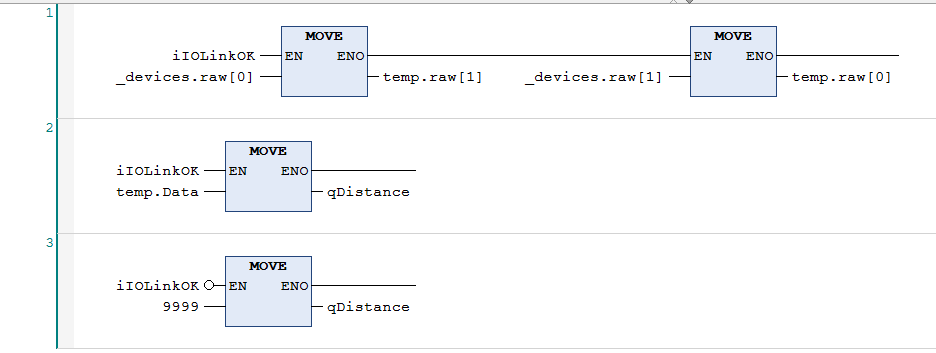
| FUNCTION_BLOCK FB_LR_TB2000 VAR_INPUT iIOLinkOK :BOOL; END_VAR VAR_OUTPUT qDistance :WORD; END_VAR VAR _devices AT %I* :uDUT_LR_TB2000; temp :uDUT_LR_TB2000; END_VAR |
Swaps the Byte and outputs the current value.
MAIN
This is the Main Program.
It is a simple program that takes IOLINK Device data and controls the DI/DO of Port4,5.
| PROGRAM MAIN VAR LR_TB2000_1:FB_LR_TB2000; AL1322_1 :FB_IFM_AL1322; Distance :WORD; Port4,Port5 :DUT_IFM_AL1322_Qualifier; Port5_Outputs AT %q*:USINT; END_VAR LR_TB2000_1( iIOLinkOK:=AL1322_1.GetIOLinkSts(1) ,qDistance=>Distance ); Port4:=AL1322_1.GetQualifier(4); Port5:=AL1322_1.GetQualifier(5); IF NOT Port4.DI2 THEN Port5_Outputs:=1; ELSE Port5_Outputs:=0; END_IF |
Add Link
Finally, Link the variables and User Program of the Ethercat IOLINK Slave Al1332.
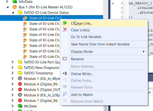
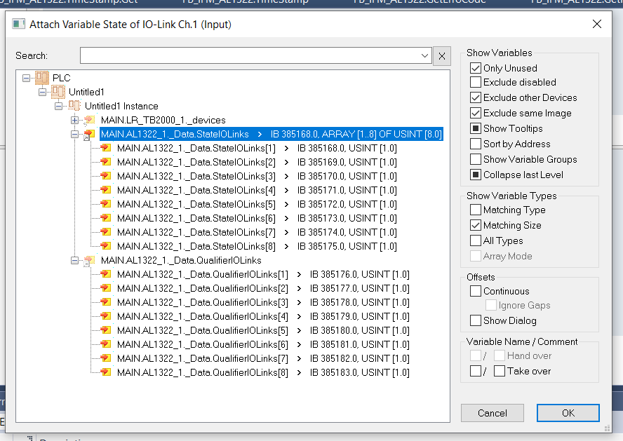
IO-Link Device Status
Link the status of each IOLINK with TxPDO IO-LINK Device Status.
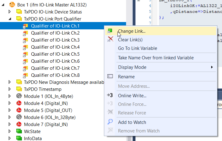
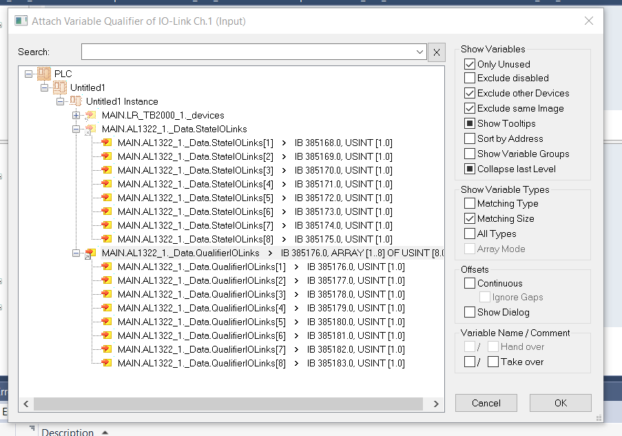
Qualifier of IO-Link
Link the evaluation of each IOLINK with the TxPDO IO-LINK Qualifier.
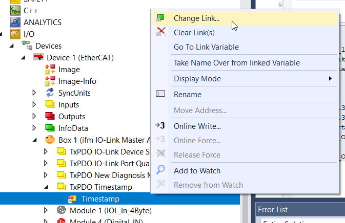
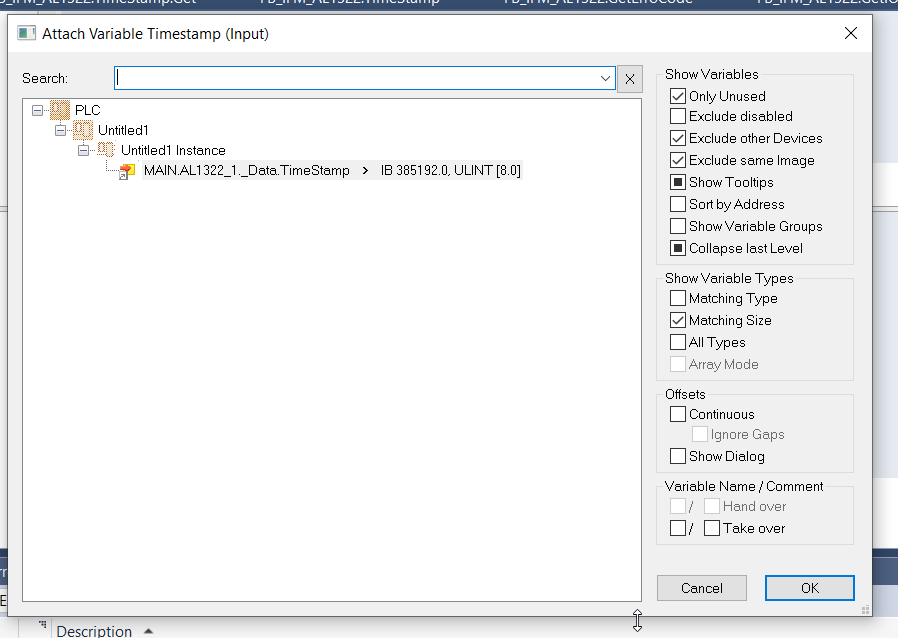
Timestamp
Link AL1332 TimeStamp with TxPDO TimeStamp.
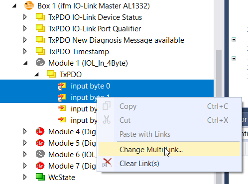
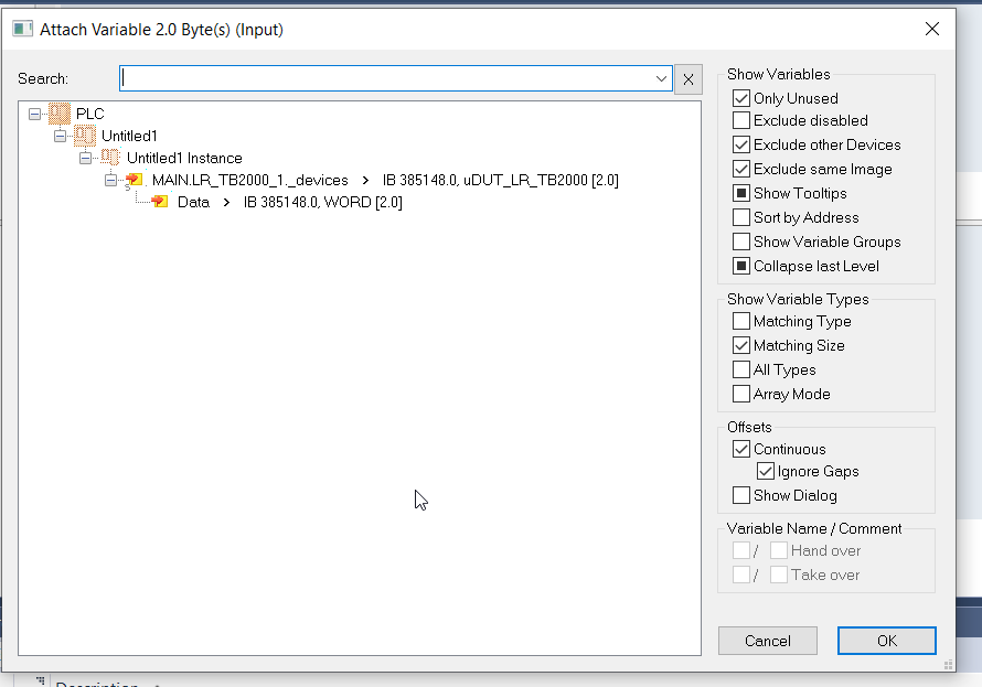
Module1(IOL_In_4Byte)
Module 1(IOL_In_4Byte)>String Byte0 and Byte1 of TxPDO with User Program.
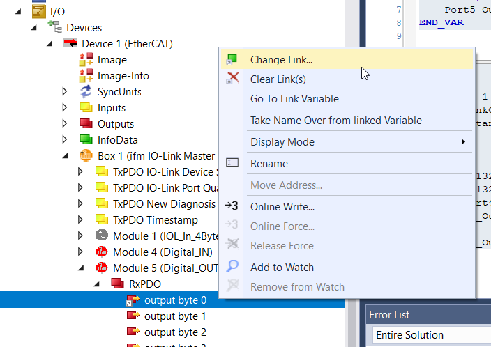
Module5(Digital OUT)
Module5>Byte 0 of RxPDO is an output, so 1 = output. String that variable with User Program.
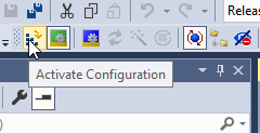
Activte
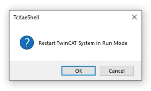
The last step is to Download the Hardware Configuration to Runtime in Activate Configuration.
Restart Runtime.
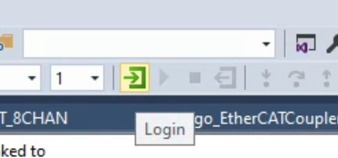
Login
Download the User Program in Login.
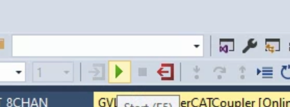
Start
Start Runtime.
Result
DI/DO
Beckhoff TwinCAT with IFM AL1332 Ethercat IOLink and Pilz ESTOP – YouTube
IO-LINK
Beckhoff TwinCAT with IFM AL1332 Ethercat IOLink and keyence IOLink Devices – YouTube
Source Code
Download the article project from the LINK below.
https://github.com/soup01Threes/TwinCAT3/blob/main/TwinCAT_IFM_AL1332.tnzip