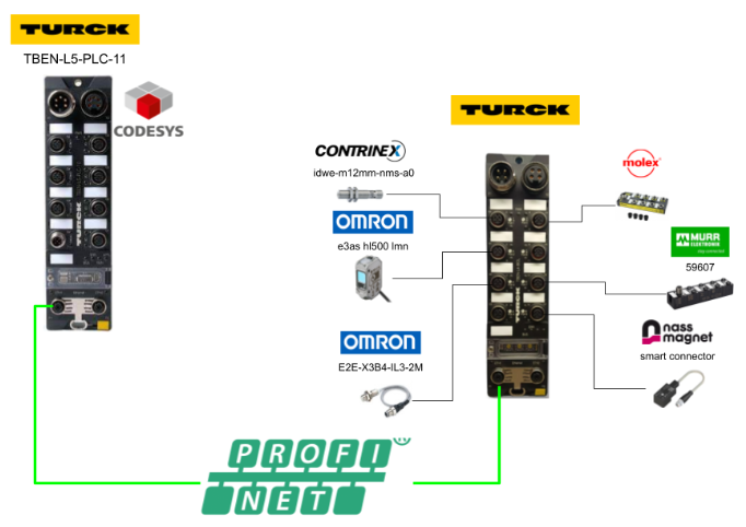
This is the second episode in a series of various Codesys articles using TURCK’s TBEN-L5-PLC-11. This time, the Profinet IO Controller is set up on the TBEN-L5-PLC-11 and connected to the TBEN-L4-8IOL, also from TURCK.
Let’s enjoy FA.
Reference Link
PROFINET IO device model…
The technical properties of PROFINET IO devices are defined by the device description file, the GSDML file.
A PROFINET IO device consists of 1 to n slots and can also contain 1 to n sub-slots. A sub-slot is a placeholder for a sub-module, which establishes an interface to the process. Submodules can contain parameters, data and diagnostics. Slot 0 is always reserved for a device access point (DAP); the DAP has a physical interface to the Ethernet network and represents a device.
Other slots and sub-slots represent other device functions. This structure is defined by the field device manufacturer. Not all slots and sub-slots need to be associated with a physical function. The allocation of slots and sub-slots and the assignment of functions (e.g. operating mode, diagnostics, etc.) is done by the PROFINET controller’s configuration software.
This device model allows manufacturers to design modular and flexible distributed field devices. Users can flexibly configure distributed field devices.
Implemenation
Cofigure Mode
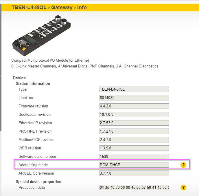
To distribute IPs from the Profinet Controller to the TBEN-L4-8IOL, set the Addressing Mode to PGM-DHCP mode.
PGM-DHCP mode 600 In PGM-DHCP mode, the gateway sends DHCP requests until a fixed IP address is allocated; the DHCP client is automatically deactivated when an IP address is allocated to the gateway via DTM or web server. DHCP client automatically deactivates when an IP address is allocated to the gateway via DTM or web server.
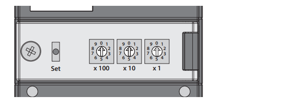
To set PGM-DHCP mode, set the Rotary switch to 600.
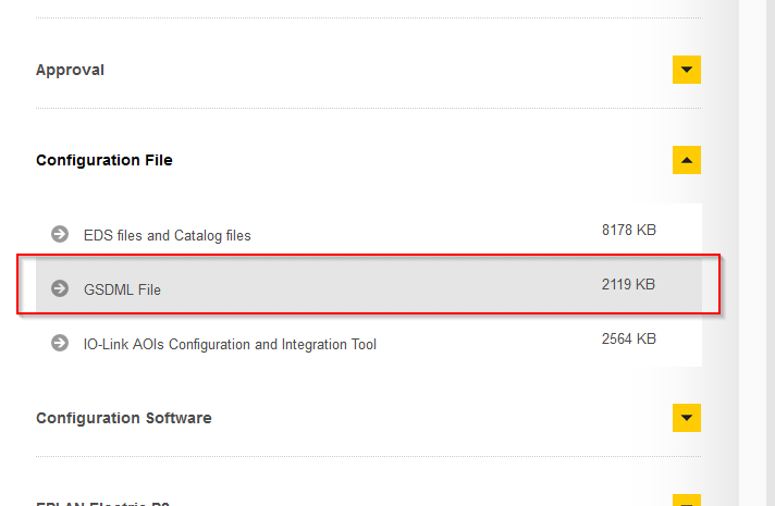
Download GSDML File
The Profinet device is the TBEN-L4-8IOL, also from Turck, so download the TBEN-L4-8IOL GSDML File from the HP.
Install the GSDML File
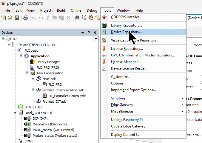
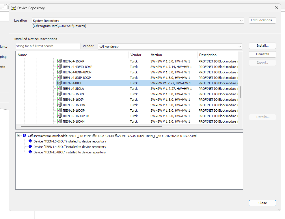
To install the GSDML File from the Codesys IDE, click Tools>Device Repository.
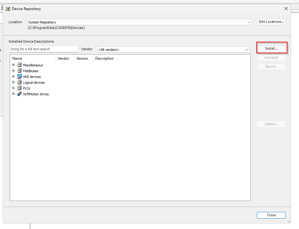
Click on the Install button.
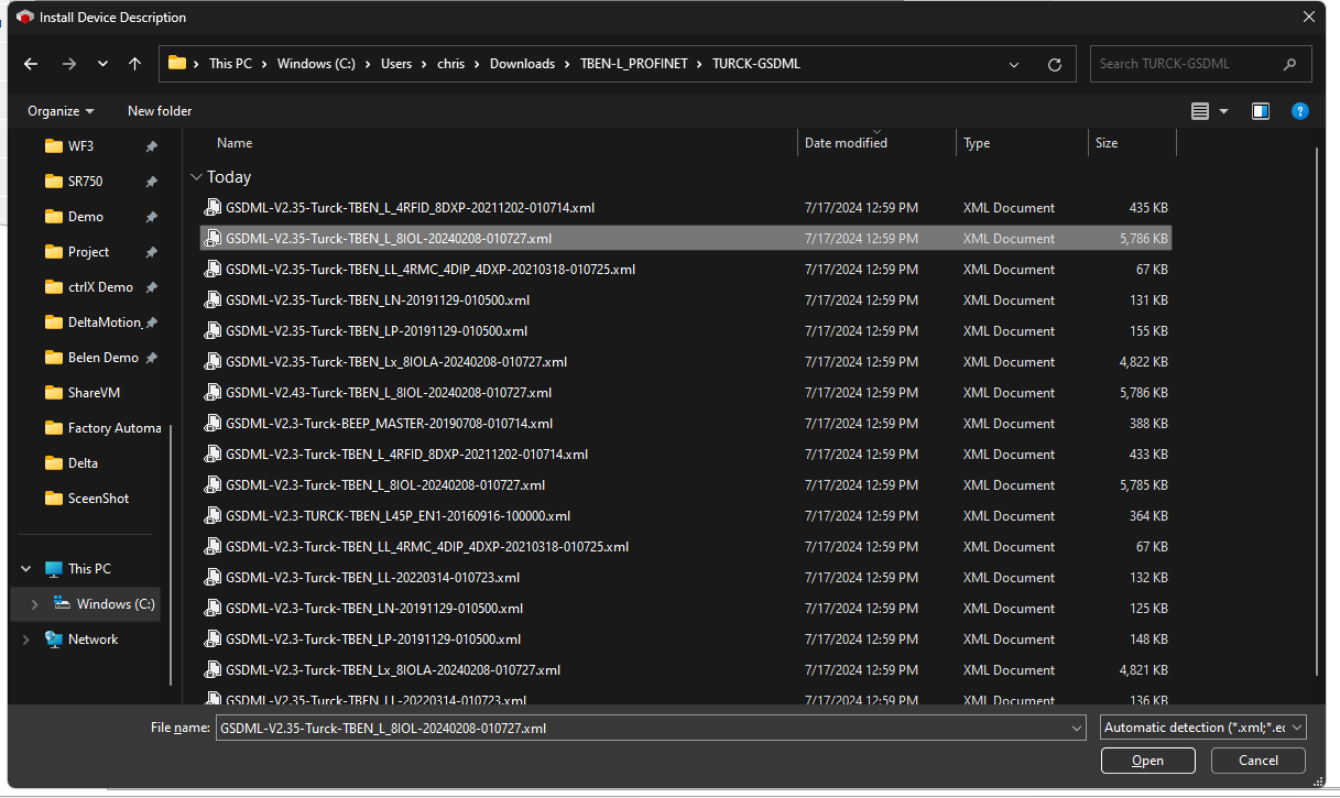
Select the TBEN-L4-8IOL GDSML File that you have just downloaded.
Done!The GSDML File is now installed in Codesys.
Configure Profinet Network
The next step is to build a Profinet network.
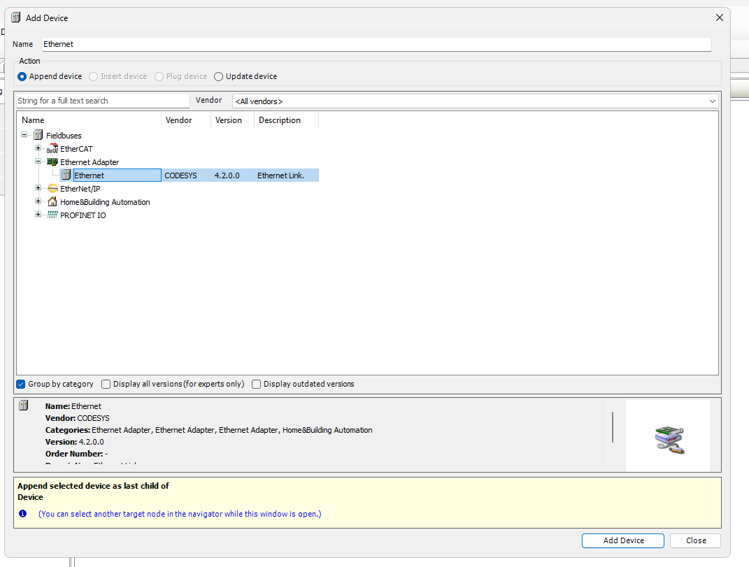
Add Ethernet Driver
Add an Ethernet Adapter: deviec>right-click>Add Device.
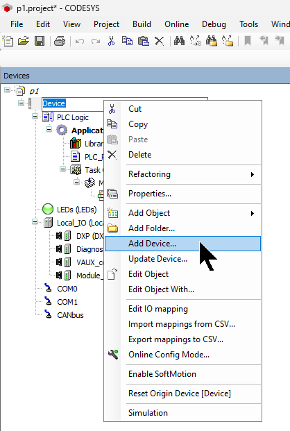
Select Ethernet Adapter>Ethernet and proceed with Add Device.
Setup Adapter
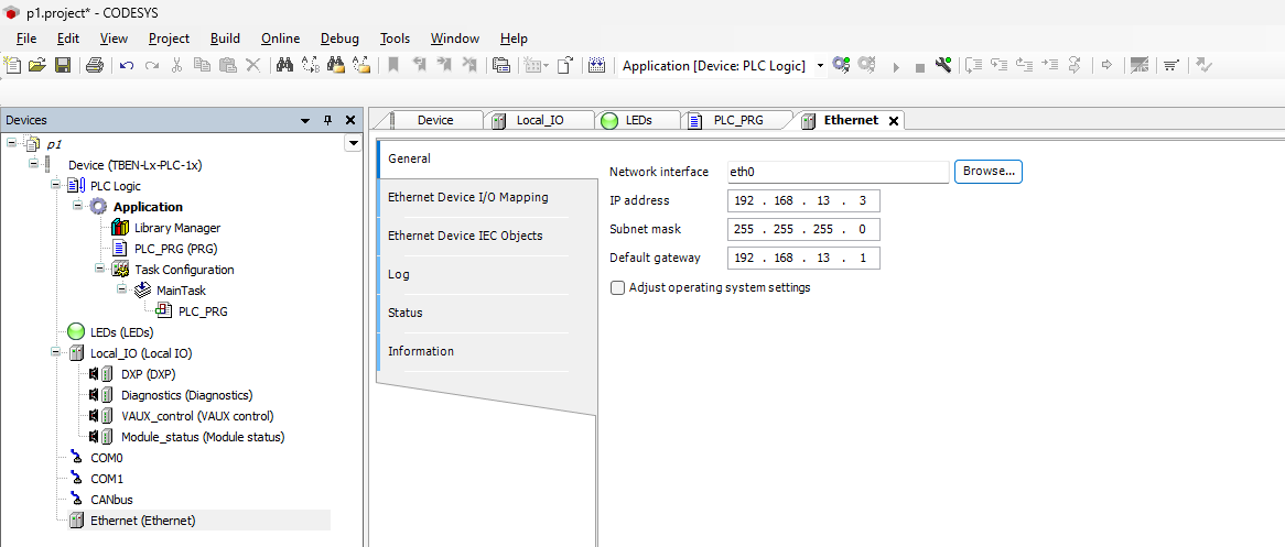
An Ethernet Adapter has been added, but Turck’s TBEN-L5-PLC-11 has two Ethernet Ports, so configure the Adapter to be used as a Profinet IO Controller for Codesys.
Click on Ethernet>General>Browse.
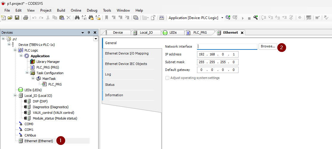
Configure the Ethernet Adapter according to your application.
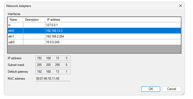
Done!
Configure Profinet IO Controller
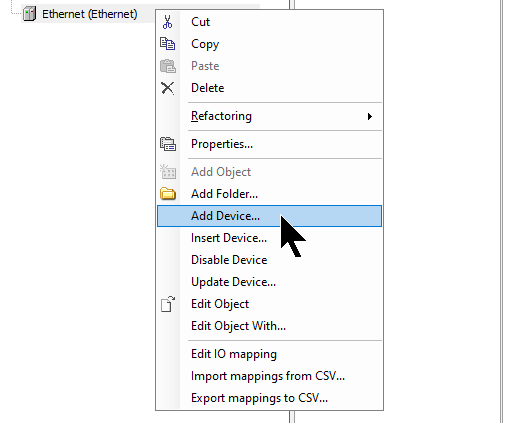
Next, add the Profinet IO Controller. Right-click the Ethernet Adapter you have just added>Add Device.
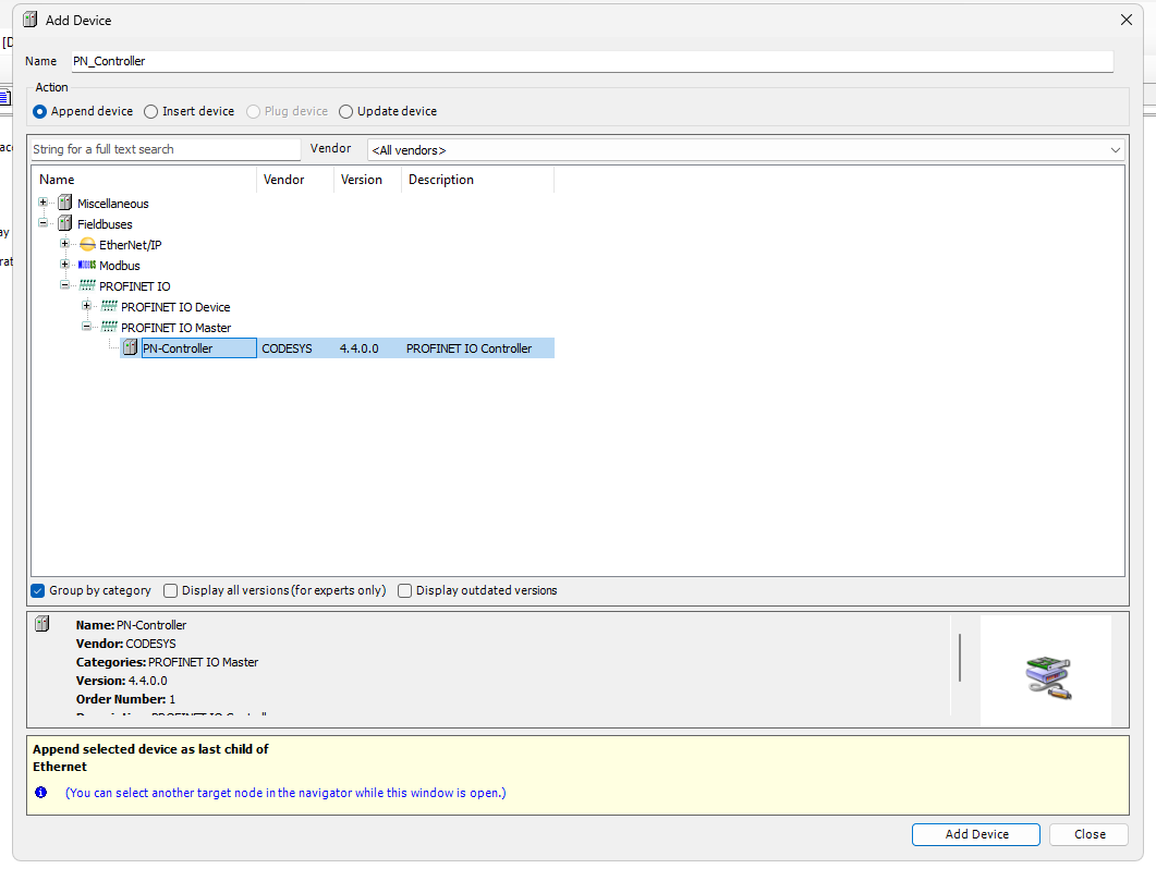
Select Fieldbus>PROFINET IO>PROFINET IO Master>PN-Controller and add it with Add Device.
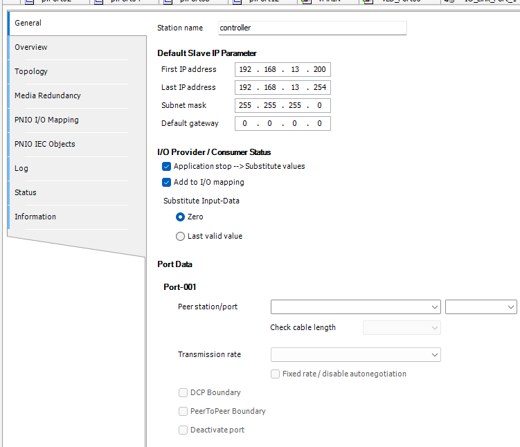
Done!Now that the PROFINET IO Controller has been added, configure the automatic assignment of Profinet IO devices in General>Default Slave IP Parameter.
In the diagram below, the initial Profinet IO device has an IP address of 192.168.13.200 and then 55 nodes up to 192.168.13.254.
Configure Profinet IO Devices
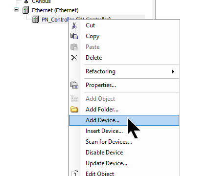
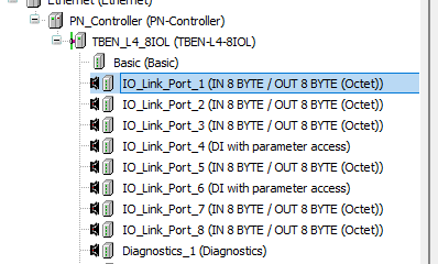
Now add the TBEN-L4-8IOL. Right-click the Profinet IO Controller you have just added>Right-click>Add Device.
Add TBEN-L4-8IOL.
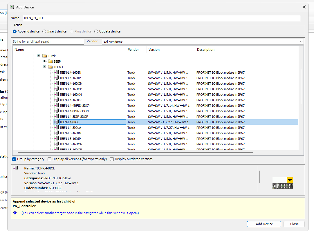
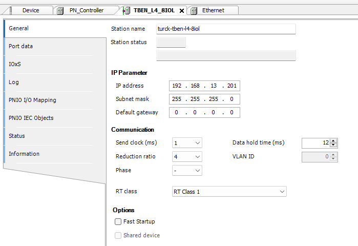
Done!Set the Profinet device name and IP address in Station Name to match the application.
Login
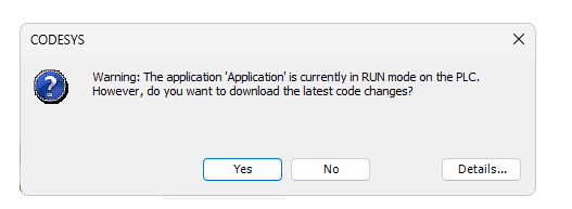
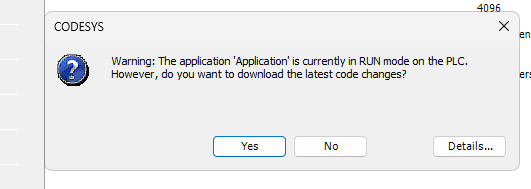
You can configure the Device name and IP address of the Profinet device in the Codesys IDE. To do this, first download the Profinet Stack from Codesys to Runtime once.
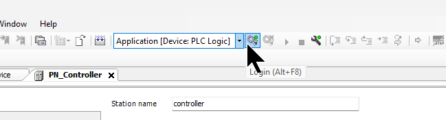
Proceed with Yes.
Done!
Scan for Devices
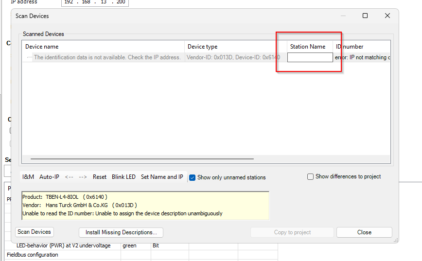
Next, click Profinet Controller>right-click>Scan for Devices.
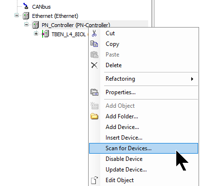
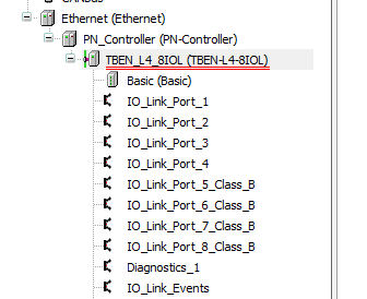
You should be able to find TBEN-L4-8IOL, so make sure that the Station Name matches the one you have set for your project.
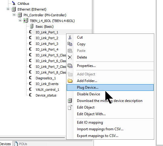
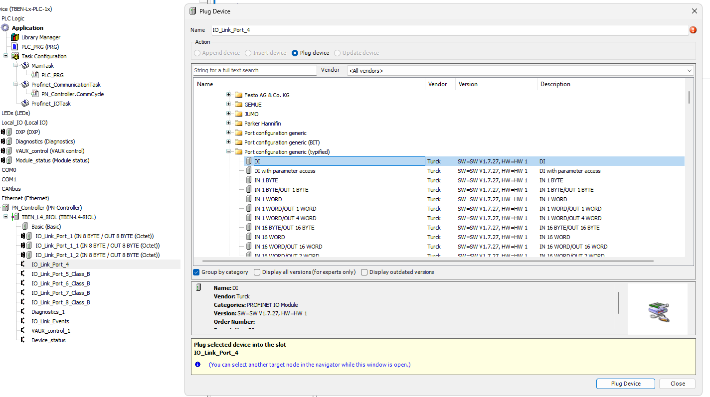
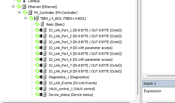
Change the Profinet Devices Slot
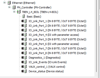
Now right-click on the relevant Slot > Plug Device to change the settings for each Port.
Select IN 8 BYTE/ OUT 8 BYTE (Octet) and click >Plug Device.
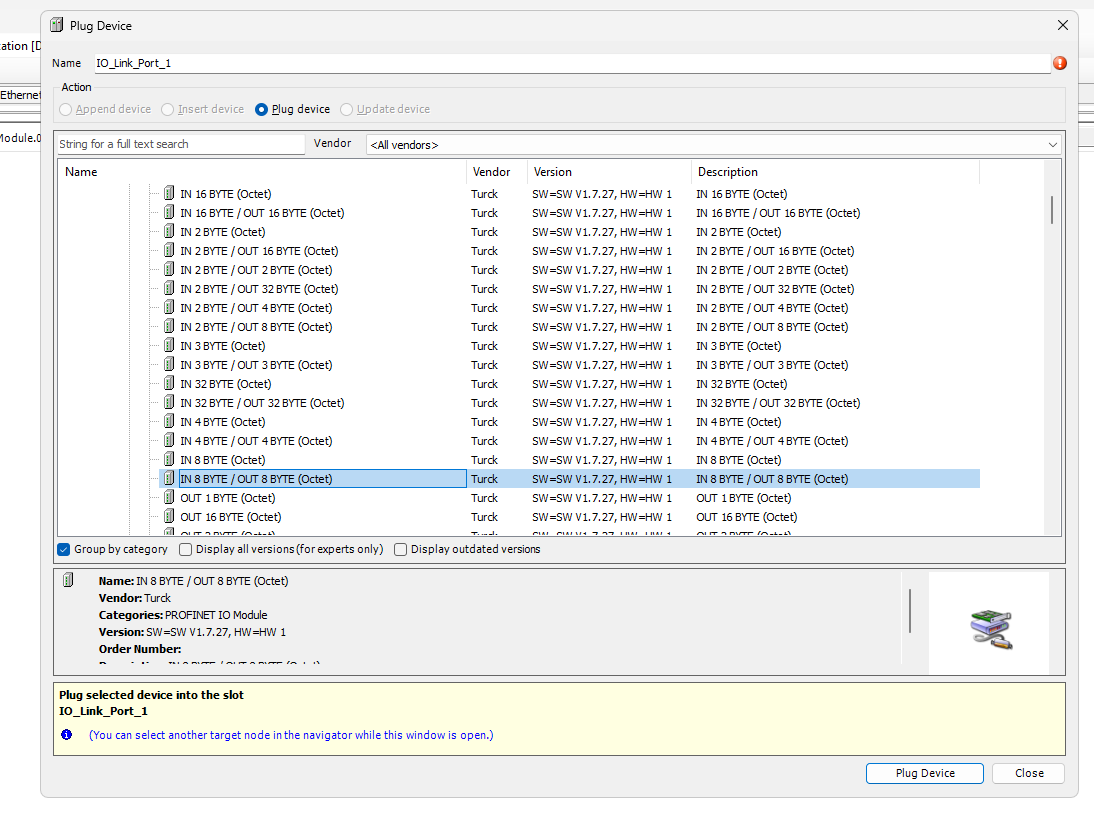
Done!The Port setting of Slot 1 has been changed.
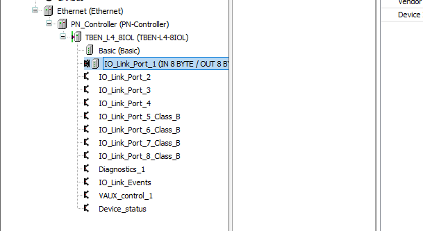
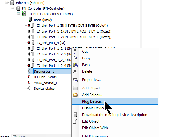
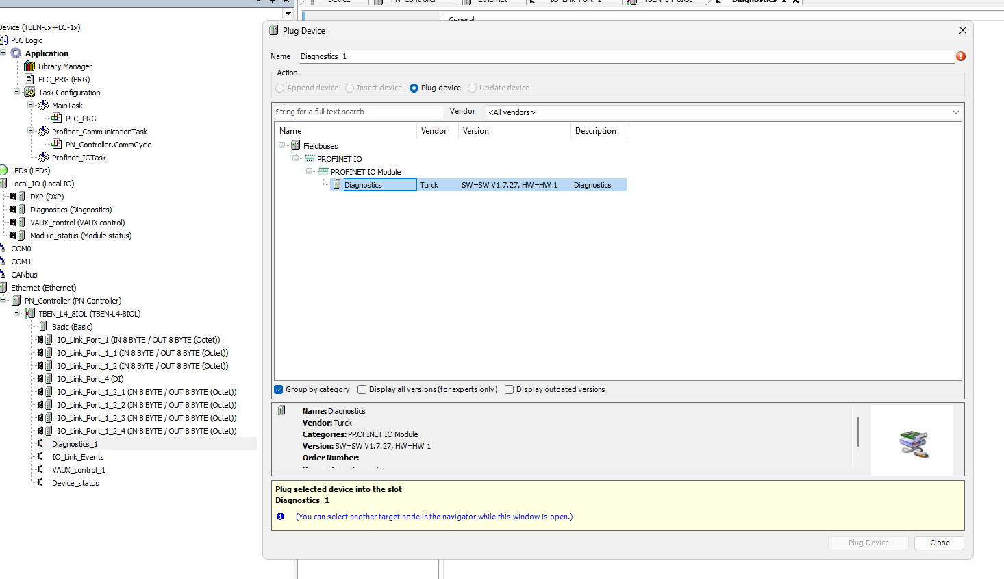
The TBEN-L4-8IOL can be built as a DIDO as well as an IO-Link.
Diagnostic information and other information can also be obtained via Profinet, so you can add devices, such as Diagnostics slots, according to your application.
Result
This is the Configuration used in this article.
Program
Now we will program the Codesys Side.
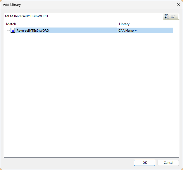
Add Library
Add library.
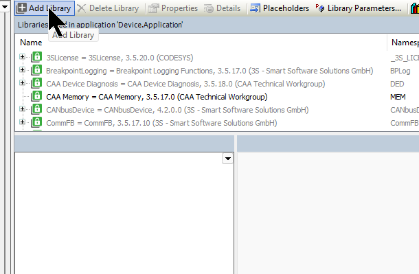
The CAA Memory library is used in this case.
DUT
Then we will Define structure.
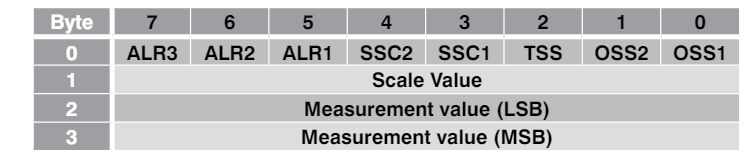
DUT_Contrinex_SmartSensor_IN
This is a structure created to match the input data of Contrinex’s IO-Link Sensor.
| TYPE DUT_Contrinex_SmartSensor_IN : STRUCT OSS1 ,OSS2 ,TSS ,SSC1 ,SSC2 ,ALR1 ,ALR2 ,ALR3 :BIT; ScaleValue :BYTE; MeasureValue:LREAL; END_STRUCT END_TYPE |
DUT_Molex_IOLINKHub_IN
This is a structure created for the input data of Molex’s IO-Link Hub.
| TYPE DUT_Molex_IOLINKHub_IN : STRUCT i00 ,i01 ,i02 ,i03 ,i04 ,i05 ,i06 ,i07 ,i08 ,i09 ,i10 ,i11 ,i12 ,i13 ,i14 ,i15 :BIT; END_STRUCT END_TYPE |
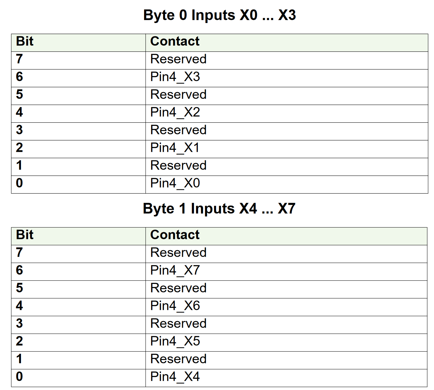
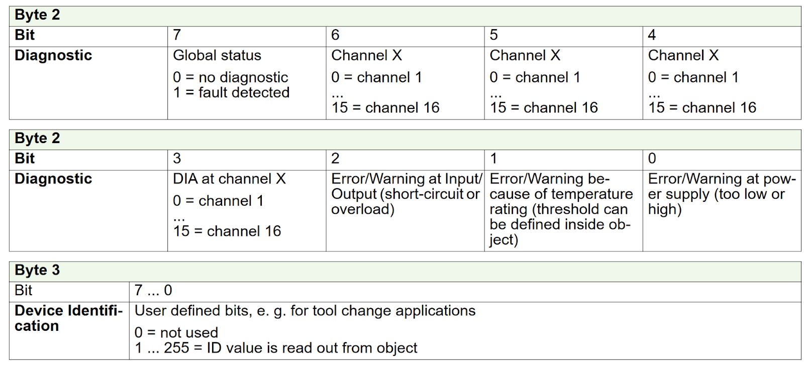
DUT_Murr_59607_IN
This is a structure created to match the input data of Murrelektronik’s IO-Link Hub 59607.
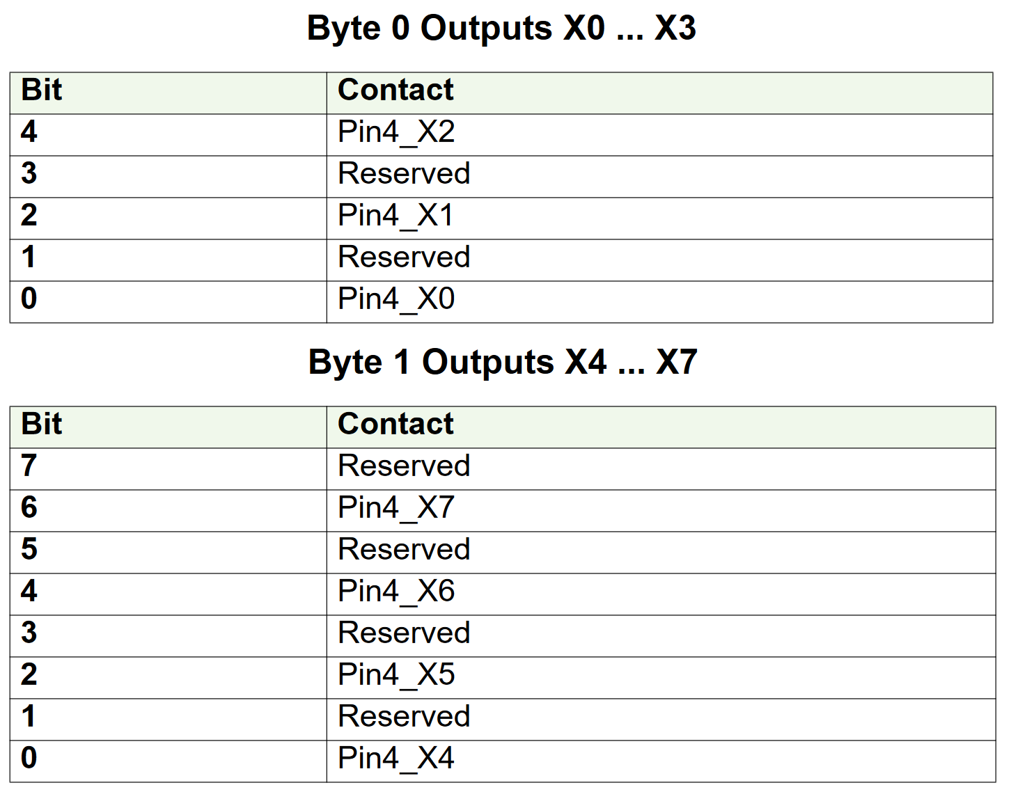
| TYPE DUT_Murr_59607_IN : STRUCT Pin4_X0 ,r0 ,Pin4_X1 ,r1 ,Pin4_X2 ,r2 ,Pin4_X3 ,r3 ,Pin4_X4 ,r4 ,Pin4_X5 ,r5 ,Pin4_X6 ,r6 ,Pin4_X7 ,r7 :BIT; DIA :WORD; ErrroPowerSupply ,ErrorTempature ,ErrorInputOutput ,GlobalStatus:BIT; END_STRUCT END_TYPE |
DUT_Murr_59607_OUT
This is a structure created to match the output data of Murrelektronik’s IO-Link Hub 59607.
| TYPE DUT_Murr_59607_OUT : STRUCT Pin4_X0 ,r0 ,Pin4_X1 ,r1 ,Pin4_X2 ,r2 ,Pin4_X3 ,r3 ,Pin4_X4 ,r4 ,Pin4_X5 ,r5 ,Pin4_X6 ,r6 ,Pin4_X7 ,r7 :BIT; END_STRUCT END_TYPE |
DUT_Nassmagnet_SmartConnector_IN
This is a structure created for Nassmagnet’s Smart Connector input data.
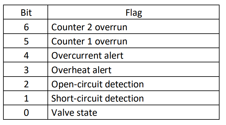
| TYPE DUT_Nassmagnet_SmartConnector_IN : STRUCT ValveState ,ShortCircuitDetection ,OpenCircuitDetection ,OverHeat ,OverCurrent ,Counter1Overun ,Counter2Overrun :BIT; END_STRUCT END_TYPE |
DUT_Nassmagnet_SmartConnector_OUT
This is a structure created to match the output data of Nassmagnet’s Smart Connector.
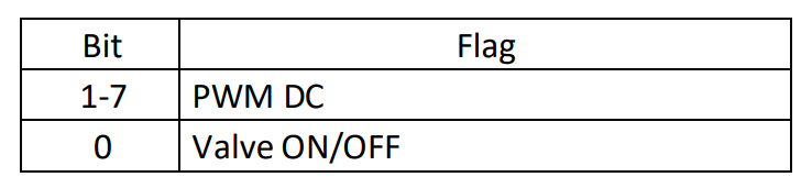
| TYPE DUT_Nassmagnet_SmartConnector_OUT : STRUCT CMD:BIT; PWM:BYTE; END_STRUCT END_TYPE DUT_OMRON_E2E_X3B4_IL3_2M_IN TYPE DUT_OMRON_E2E_X3B4_IL3_2M_IN : STRUCT MonitorData:BYTE; ControlOutput ,r0 ,r1 ,r2 ,Unstable ,TooClose ,r3 ,ERROR :BIT; END_STRUCT END_TYPE |
DUT_OMRON_E3ASHL500MN_IN
This is a structure created to match the input data of OMRON’s E3ASHL500MN.
| TYPE DUT_OMRON_E3ASHL500MN_IN : STRUCT DelectValue:WORD; LightLevel:BYTE; ControlOutput1 ,ControlOutput2 ,InstabliltyAlarm ,r0 ,InsufficientAlarm ,r1 ,Warning ,ERROR :BIT; END_STRUCT END_TYPE |
DUT_OMRON_E2E_X3B4_IL3_2M_IN
This is a structure created for OMRON’s E2E-X3B4-IL3-2M input data.
| TYPE DUT_OMRON_E2E_X3B4_IL3_2M_IN : STRUCT MonitorData:BYTE; ControlOutput ,r0 ,r1 ,r2 ,Unstable ,TooClose ,r3 ,ERROR :BIT; END_STRUCT END_TYPE |

GVL
Define variables in the GVL for Mapping with Turck’s IO-Link Master.
| {attribute ‘qualified_only’} VAR_GLOBAL Port00_IN:ARRAY[0..7]OF BYTE; Port02_IN:ARRAY[0..7]OF BYTE; Port04_IN:ARRAY[0..7]OF BYTE; Port08_IN:ARRAY[0..7]OF BYTE; Port12_IN:ARRAY[0..7]OF BYTE; Port12_Out:ARRAY[0..7]OF BYTE; Port14_IN:ARRAY[0..7]OF BYTE; Port14_Out:ARRAY[0..7]OF BYTE; Baisc:ARRAY[0..3]OF USINT; Port00_Diagnostics:ARRAY[0..1]OF USINT; Port02_Diagnostics:ARRAY[0..1]OF USINT; Port04_Diagnostics:ARRAY[0..1]OF USINT; Port06_Diagnostics:ARRAY[0..1]OF USINT; Port08_Diagnostics:ARRAY[0..1]OF USINT; Port10_Diagnostics:ARRAY[0..1]OF USINT; Port12_Diagnostics:ARRAY[0..1]OF USINT; Port14_Diagnostics:ARRAY[0..1]OF USINT; Port012_Diagnostics: POINTER TO BYTE; END_VAR |
POU
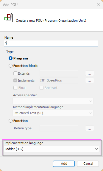
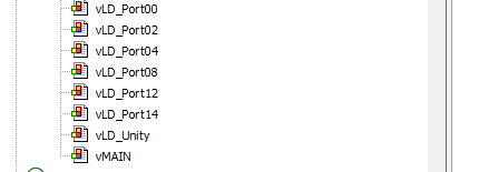
This article will use LD2, so click Application>Add Object>POU.

Select Implementation Language as LD2 and proceed with >Add.
p
Define the variables required by the POU.
| PROGRAM p VAR _TempBytes:ARRAY[0..7]OF BYTE; _TempWORD:WORD; _TempReal:REAL; _IOPortOK:ARRAY[0..15]OF BOOL; _Port1INPUTData:DUT_Contrinex_SmartSensor_IN; _Port2INPUTData:DUT_OMRON_E3ASHL500MN_IN; _Port3INPUTData:DUT_OMRON_E2E_X3B4_IL3_2M_IN; _Port5INPUTData:DUT_Molex_IOLINKHub_IN; _Port7INPUTData:DUT_Murr_59607_IN; _Port7OUTPUTData:DUT_Murr_59607_OUT; _Port8INPUTData:DUT_Nassmagnet_SmartConnector_IN; _Port8OUTPUTData:DUT_Nassmagnet_SmartConnector_OUT; TONs:ARRAY[0..1]OF TON; END_VAR |
Add Action to the POU.
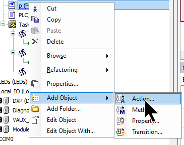
The added Action is then called in the programme.
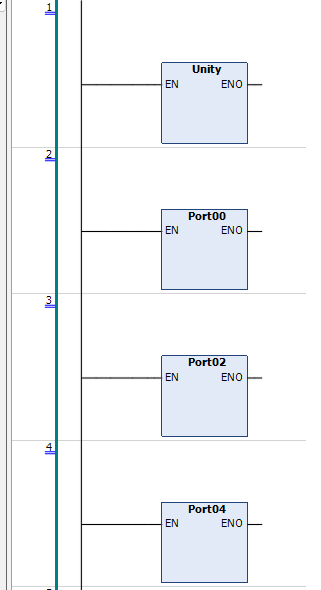
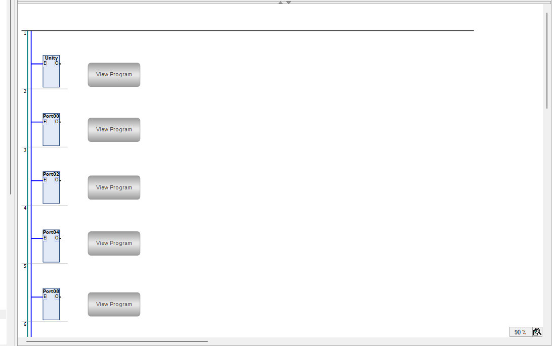
Action:Unity
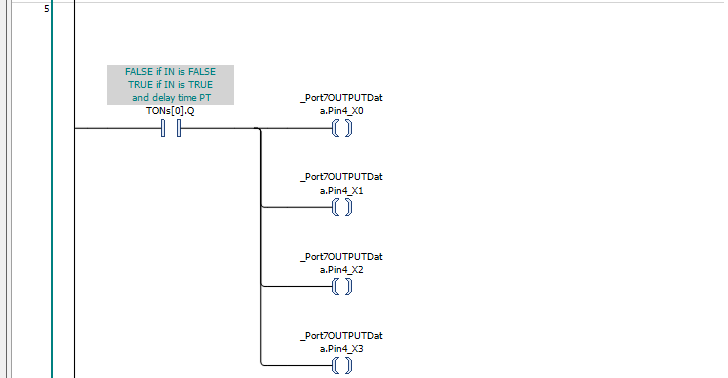
The Action Block here generates a 1 second ON/OFF repetitive Bit.

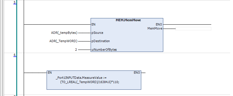
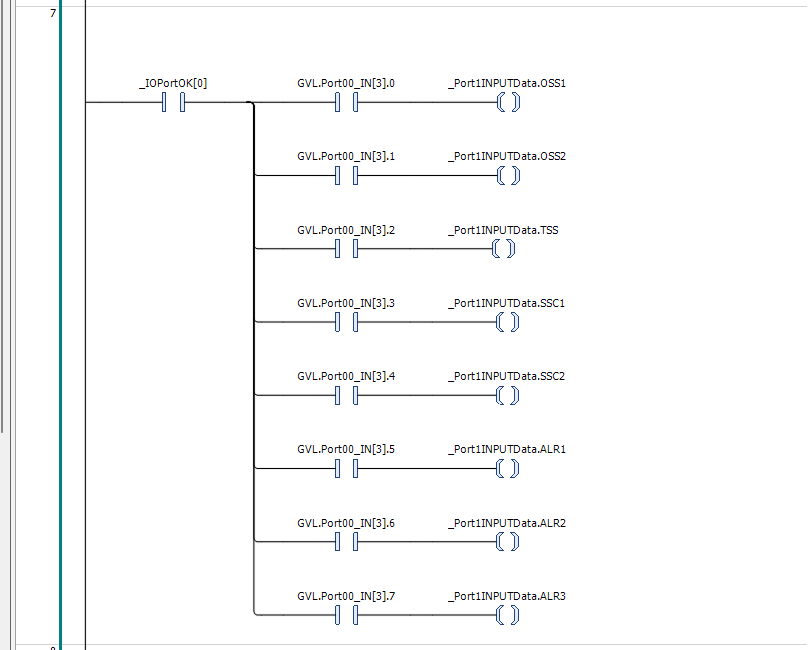
Action:Port00
This Action Block processes data from Contrinex IO-Link Sensors, which are connected to Port 00 of the Turck IO-Link Master TBEN-L4-8IOL.

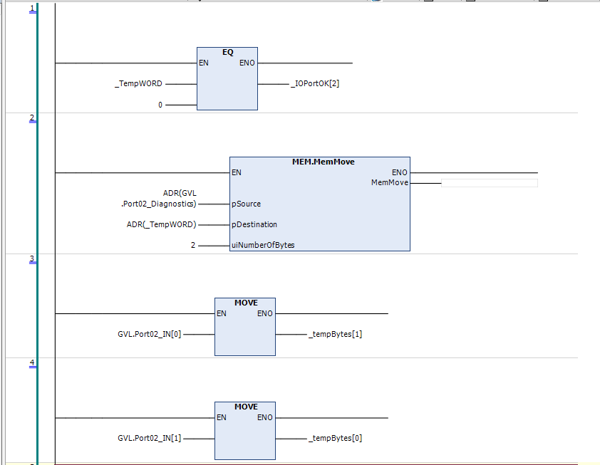
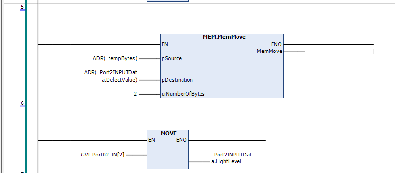
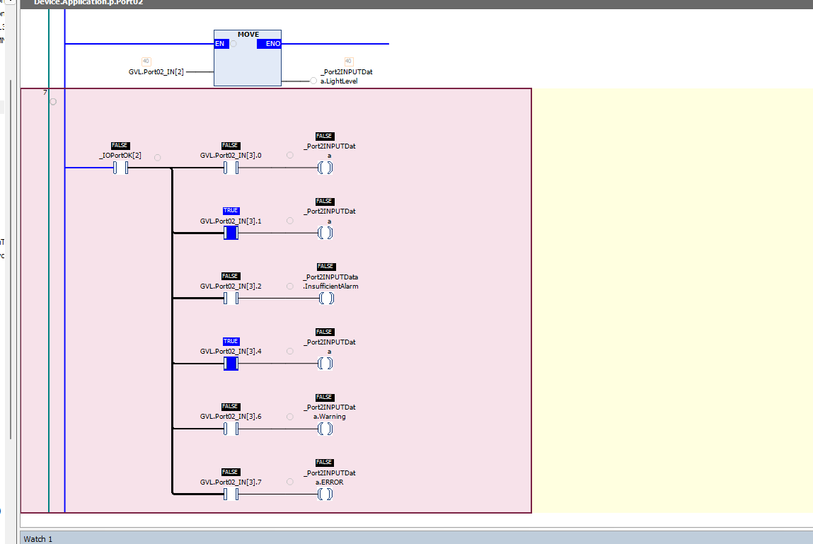
Action:Port02
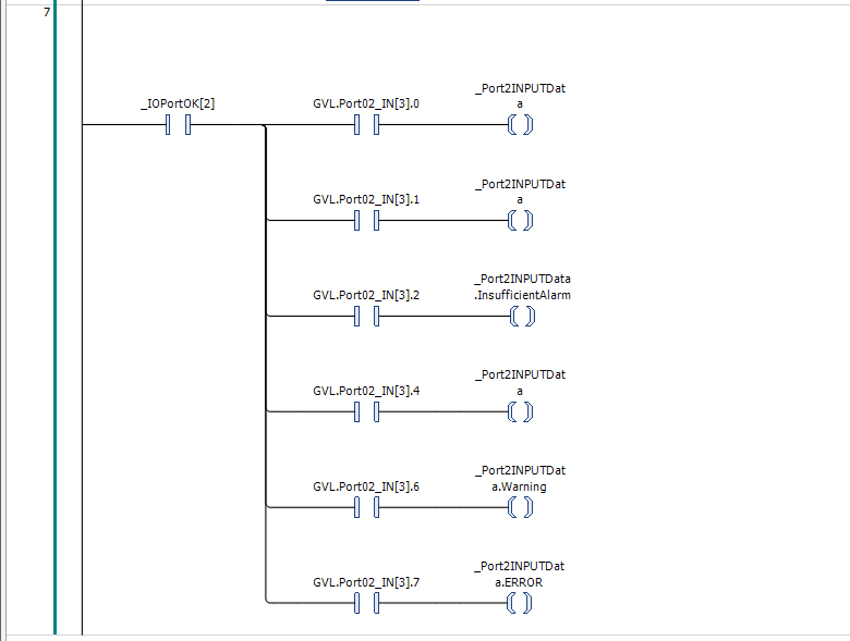
This Action Block processes data from OMRON’s E3ASHL500MN, which is connected to Port02 of Turck’s IO-Link Master TBEN-L4-8IOL.
Action:Port04
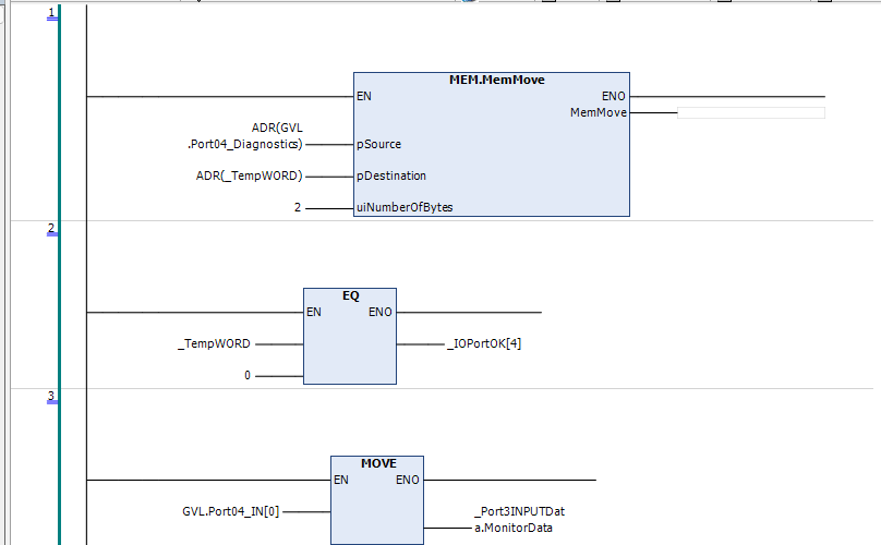
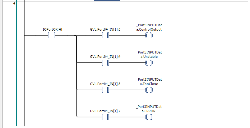
This Action Block processes data from OMRON’s E2E-X3B4-IL3-2M, which is connected to Port 04 of Turck’s IO-Link Master TBEN-L4-8IOL.
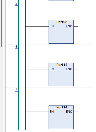
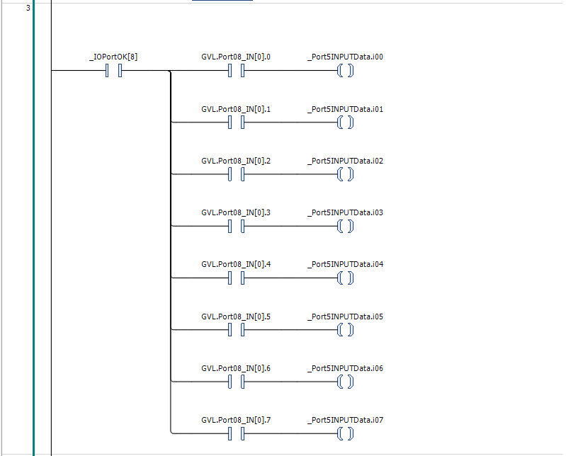
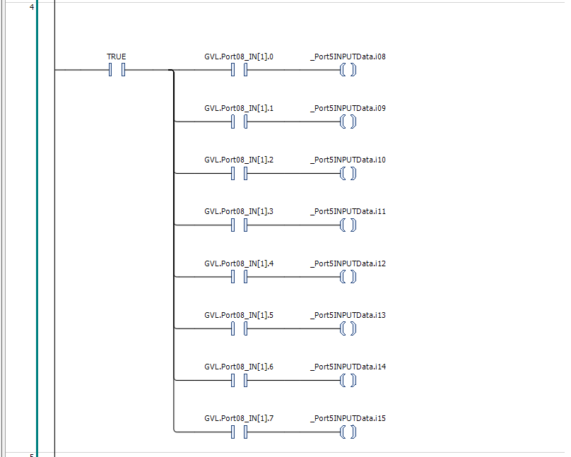
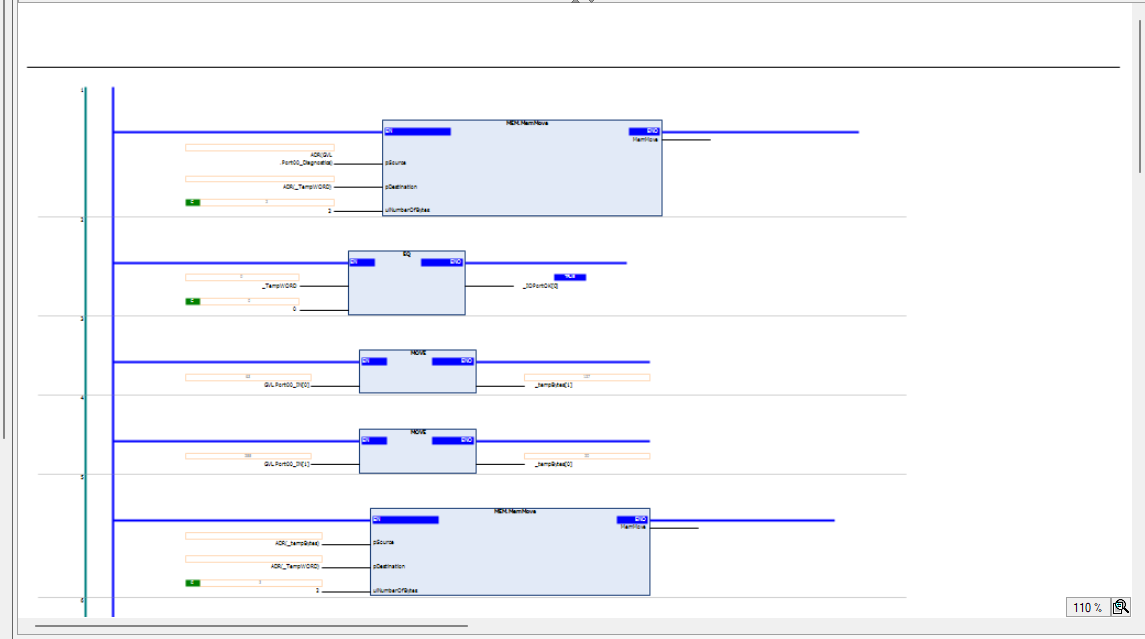
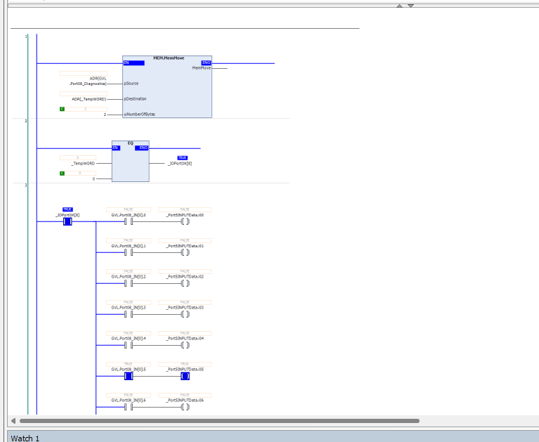
Action:Port08
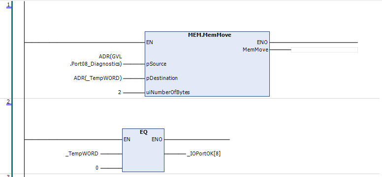
This Action Block processes data from Molex’s IO-Link Hub, which connects to Port 08 on Turck’s IO-Link Master TBEN-L4-8IOL.
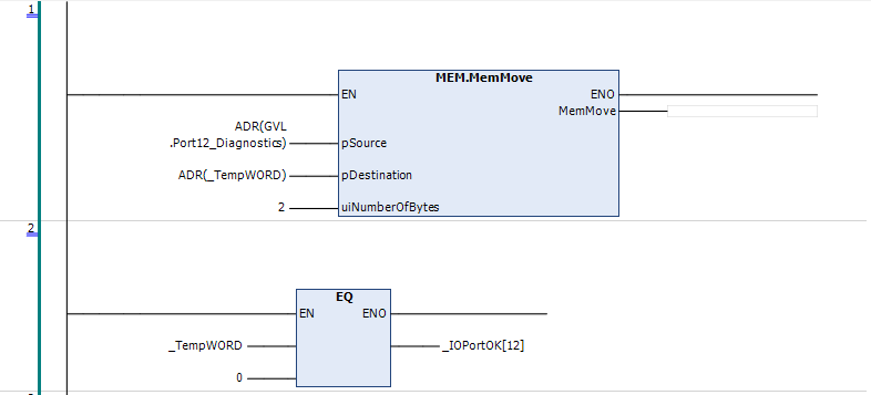
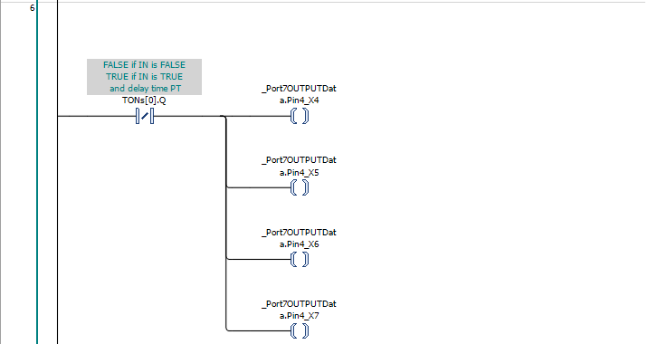
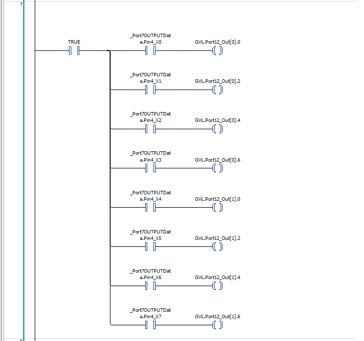
Action:Port12
This Action Block processes Murrelektronik’s IO-Link Hub 59607 data, which is connected to Port 12 of Turck’s IO-Link Master TBEN-L4-8IOL.


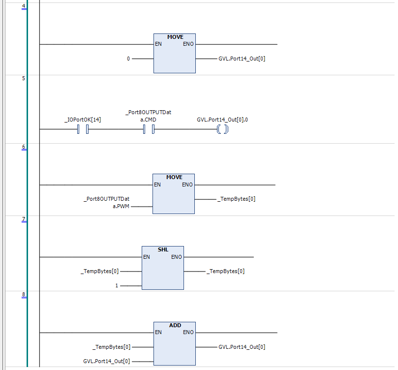
Action:Port14
This Action Block processes Nassmagnet Smart Connector data that connects to Port 12 of Turck’s IO-Link Master TBEN-L4-8IOL.


PLC_PRG
Finally, call the POUs you have just created into the MAIN programme.
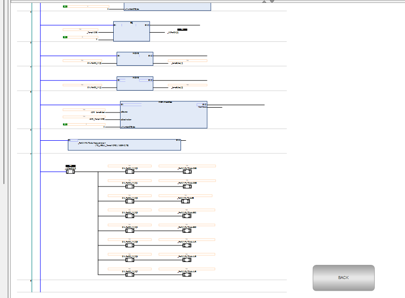
| p(); |
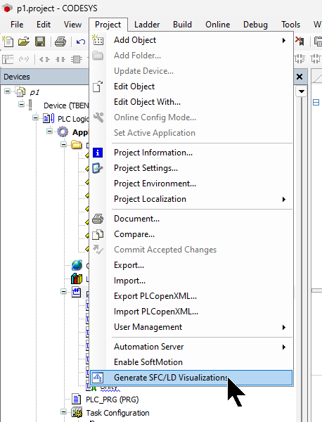
Generate SFC/LD Visualizations
Generate a programme monitoring screen for SFC/LD Click on Project>Generate SFC/LD Visualisation.
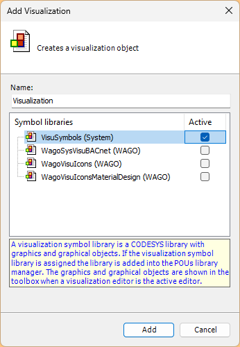
Visualization
Next, click Add Object>Visualisation to add a Visualisation.
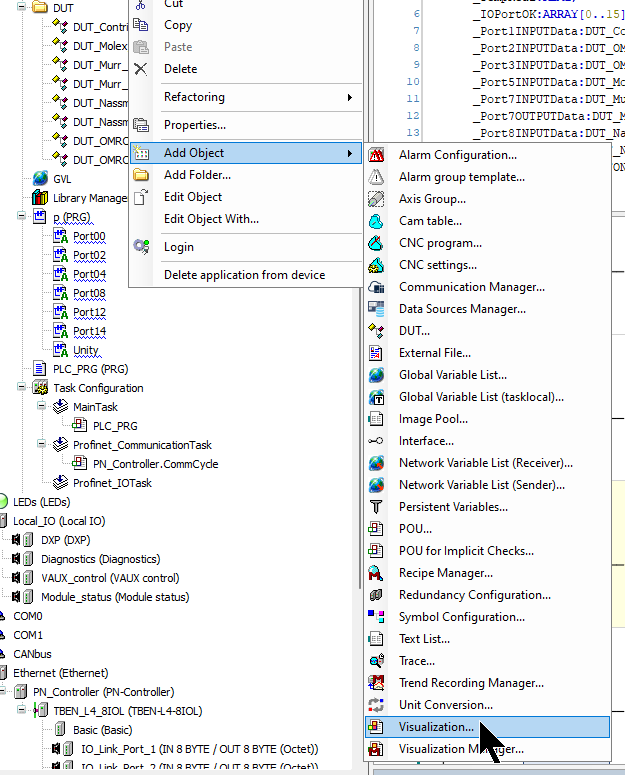
Select VisuSymbols(System) and add a screen with Add.
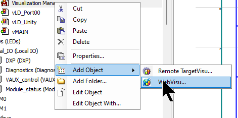
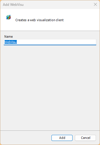
Add WebVisu
If you need to display a web page screen, use Add Object>WebVisu to add a web screen.
Screen
Finally, create a screen for monitoring the programme.
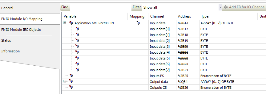
Mapping
Variables defined in the programme need to be Mapped to input/output data (Mitsubishi’s XY).
For example, in Port1, in the Variable column of Input Data, there is a button for ….
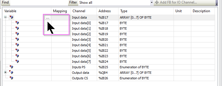
Set the appropriate variables in your programme.
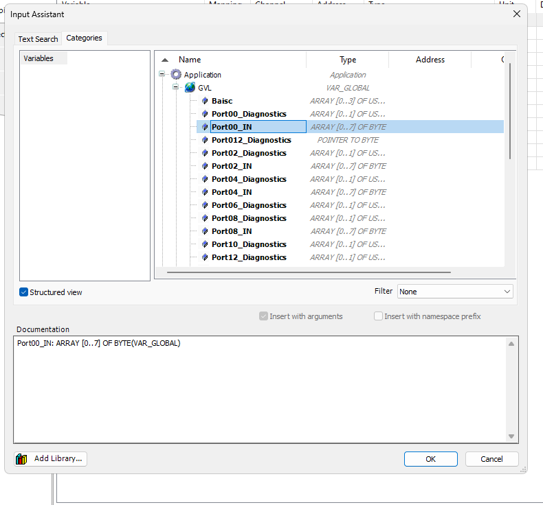
Done!
Download
Finally, download the programme to the PLC.
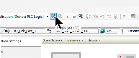
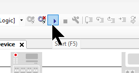
Start
Click the Start button and change Runtime to Run Mode.
Result
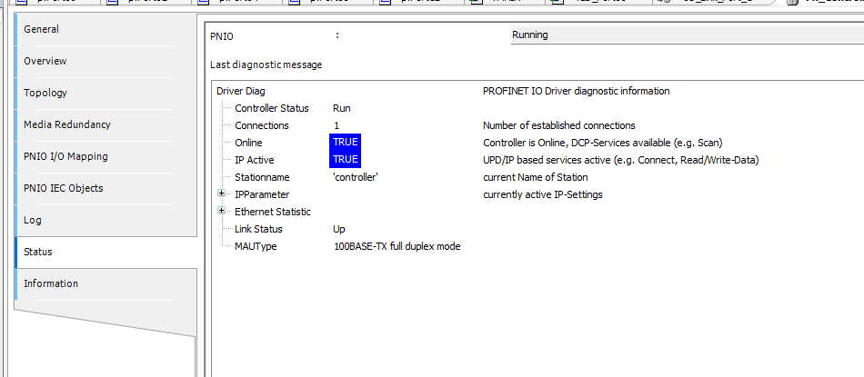
TBEN-L5-PLC-11 PLC is in RUN Mode.
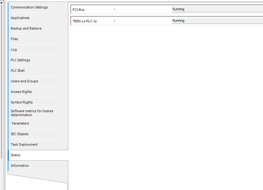
Profinet communication between TBEN-L5-PLC-11 and TBEN-L4-8IOL is ok.
Profinet Controller is currently in the Run state.
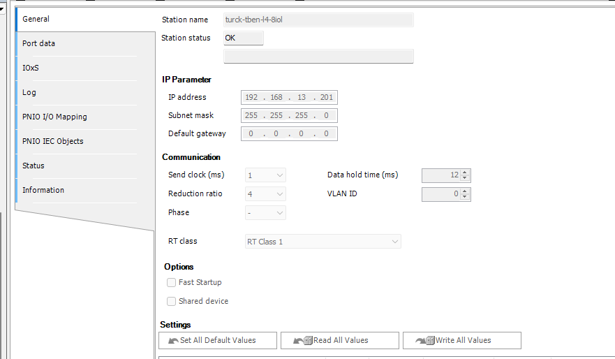
The status of the TBEN-L4-8IOL is also OK.
SFC/LD Visualisation is also working properly.
The data of the IO-Link device for each Port has been acquired.

Project
Please Download the project for this article from Github below.
https://github.com/soup01Threes/Codesys/blob/main/Turck_TBEN_Lx_PLC_1x_Tutorial01.projectarchive