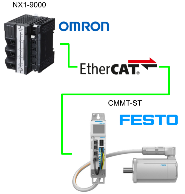
In this article, we will use OMRON’s NX1-9000 to set up EtherCAT Master and connect it to FESTO’s CMMT-ST Servo Drive.
Let’s get started!
Implementation
Festo Side
Download ESI File
Download the CMMT-ST ESI File from the Festo website.
Configuration And Setup
Please refer to this article to set up and commission the Festo CMMT-ST Servo Drive.
Omron Side
Display ESI
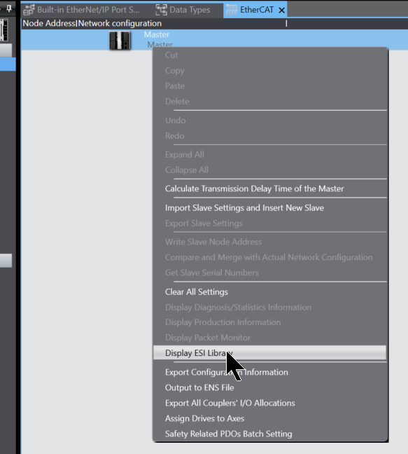
To register the Servo Drive ESI File in Festo, right-click on the EtherCAT screen>Display ESI Library.
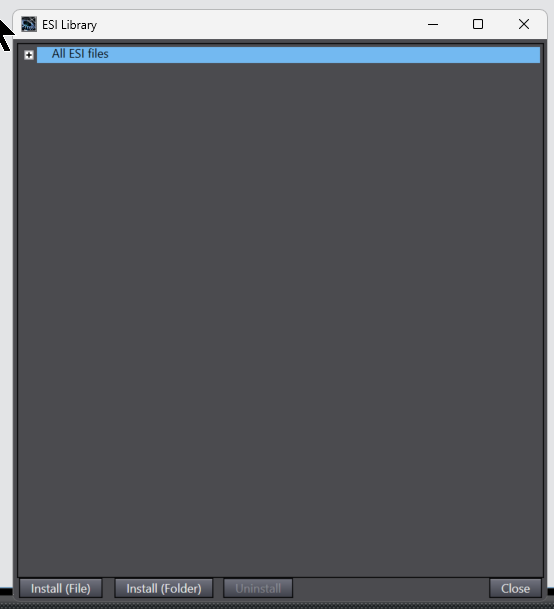
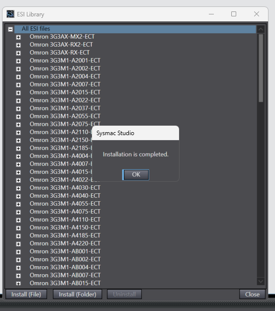
The Sysmac Studio ESI Library screen will appear, click on the Install button and install the ESI File downloaded from Festo HP.
Process with yes.
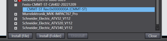
Done!
Festo’s CMMT Servo Drive is now registered.
Insert CMMT
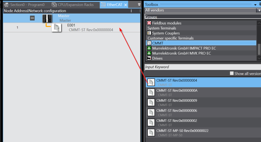
Add the CMMT-ST Servo Drive from the Toolbox to the Ethercat network.
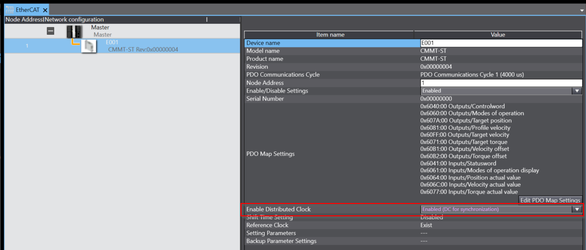
Enable the “Enable Distributed Clock” function for the CMMT-ST Servo Drive.
Add Single Axis
Next, to add a Single-Axis, click Motion Control Setup>Axis Setting>Right-click>Add>Single-axis Position Control Axis.
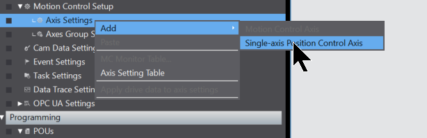
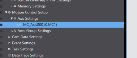
Done!A new Single Axis has been added.
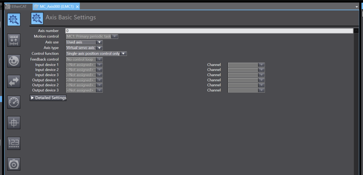
Axis Basic Setting
This Axis Basic Settings screen is used to create axes for use in motion control instructions, assign these axes to servo drives and encoders and set axis parameters.
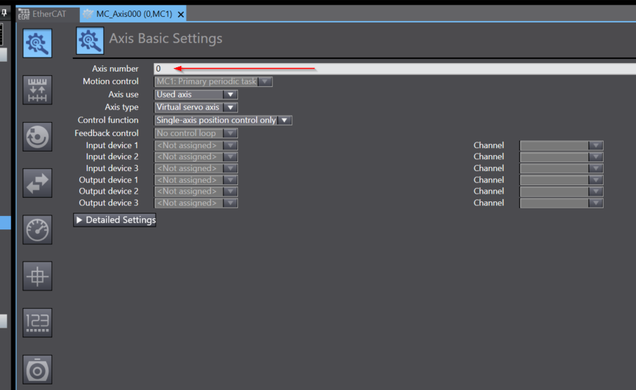
Axis Number
Axis Number sets the number of the relevant Axis.
Axis Use
For Axis Use, select ‘Used axis’.
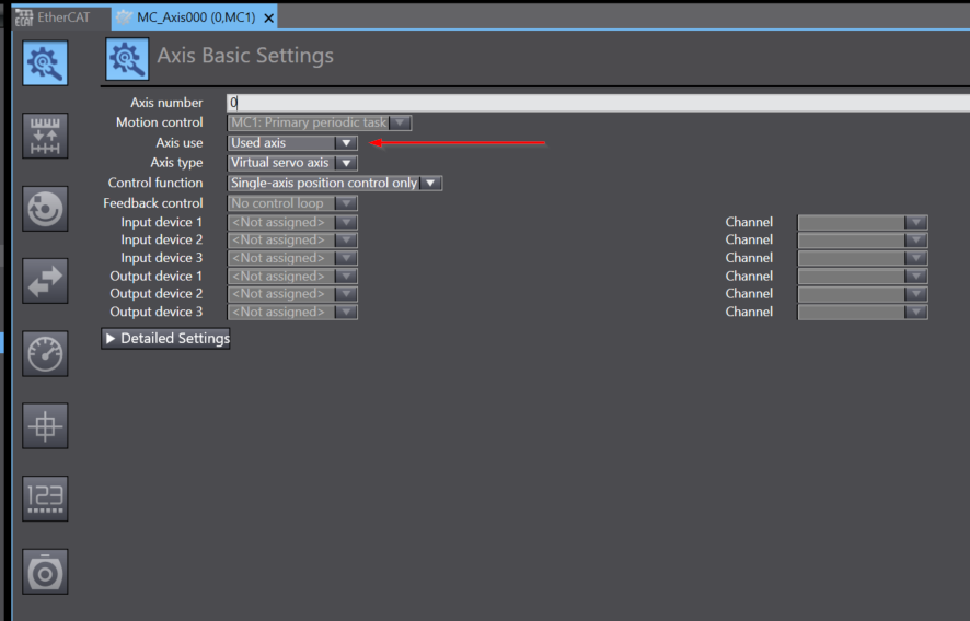
Axis Type
Next, set the Axis Type.
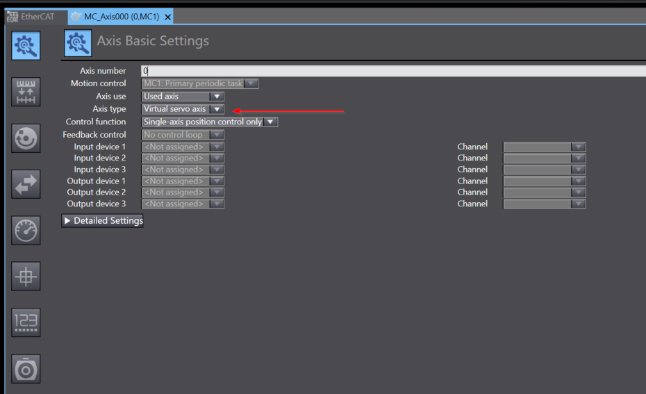
Select Servo axis from the Drop-List.
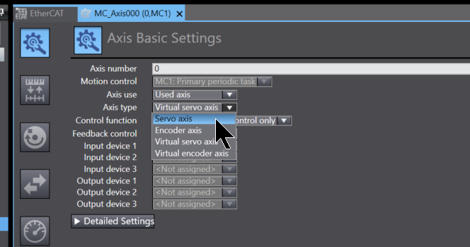
Done!
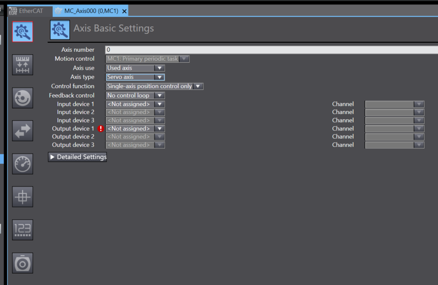
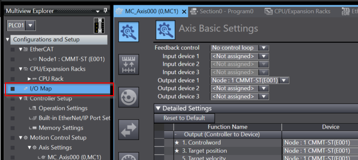
Output Device 1
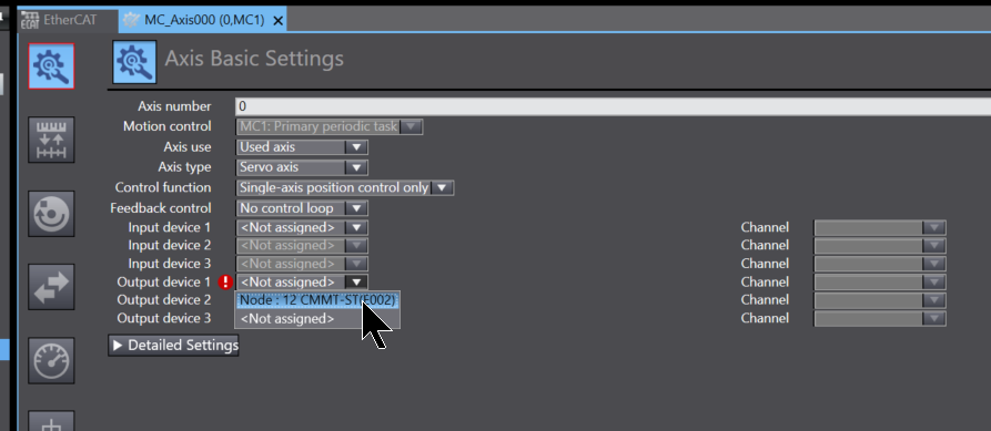
The next step is to tie this axis from the Drop-List of Output device 1 to the hardware Servo.
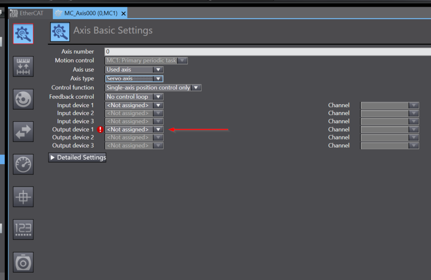
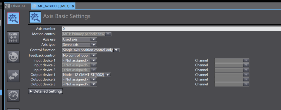
Select the Festo Servo Drive you have just added.
Done!
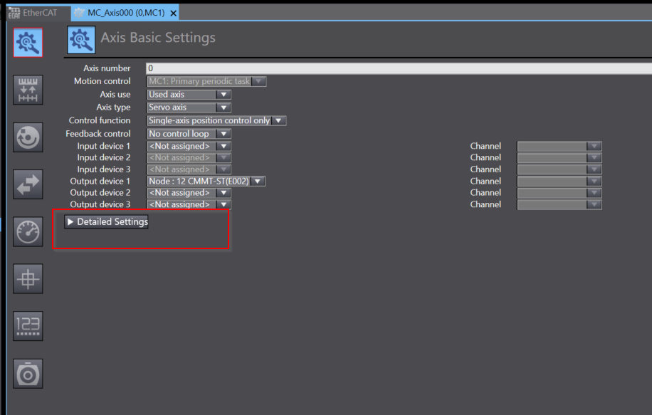
Detailed Setting
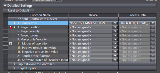
Next, click on Detailed Settings and map Process input/Output to Axis.
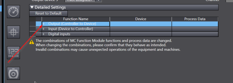
Detailed Settings Menu has three Fields Output/Input/Digital inputs.
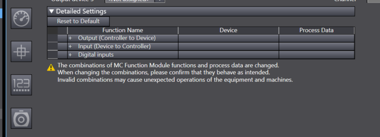
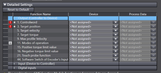
This is the data output by the OMRON NX CPU to the Festo Servo Drive.
Functions marked in red indicate items that need to be set as a minimum on the Configuration.
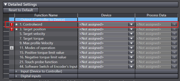
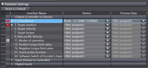
Select the Festo Servo Drive CMMT-ST from the Device Drop-List next to the Control Word.
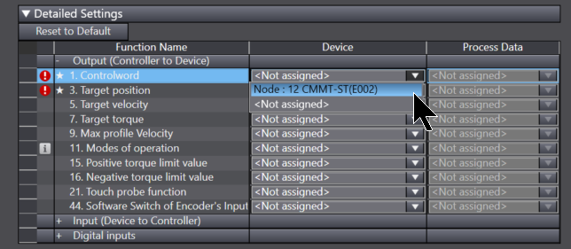
Done!
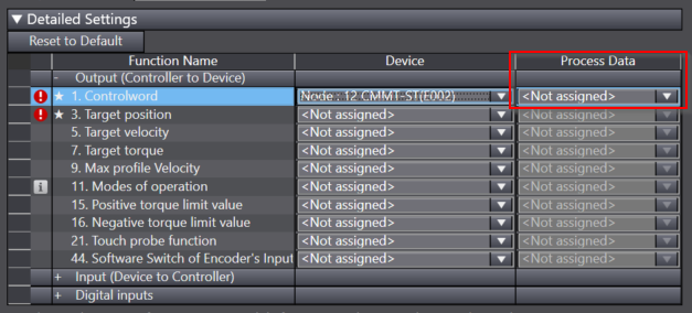
Next, a Function called Controlword maps the Process Data of the Festo Servo Drive.
Select 6040h-00.0 (Outputs_Controlword_6040_0).
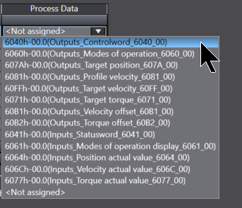
Done!
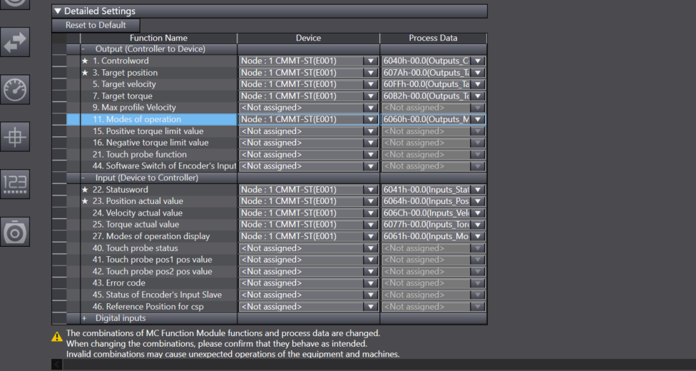
Set Function Name 1, 3, 5, 7, 22, 23, 24, 25, 27 as shown below.
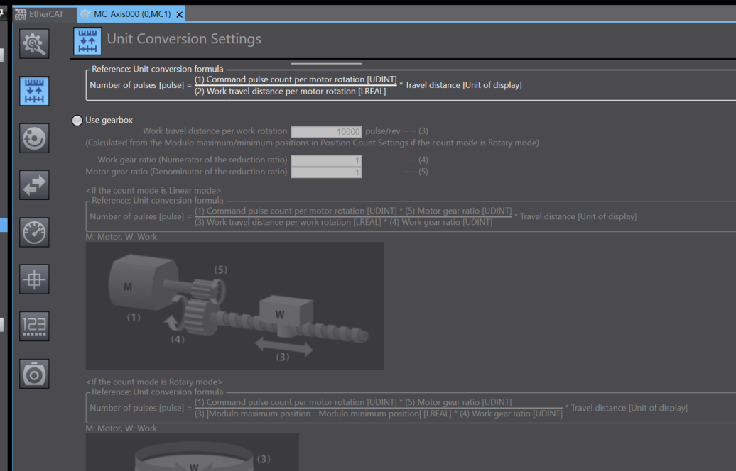
Unit Conversion Settings
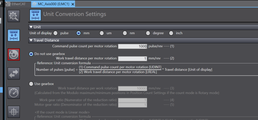
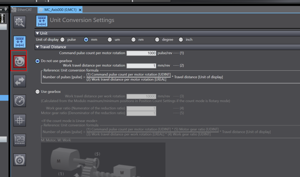
This Unit Conversion Settings screen sets the display units and gear ratio of the electronic gear. Set the number of command pulses and the travel distance per motor revolution. Note that with Unit Ver. 1.11 or later CPU Units, you can set the items when using a reduction gear.
Set Unit to mm.
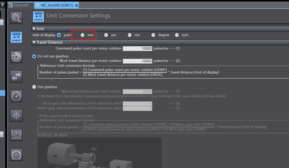
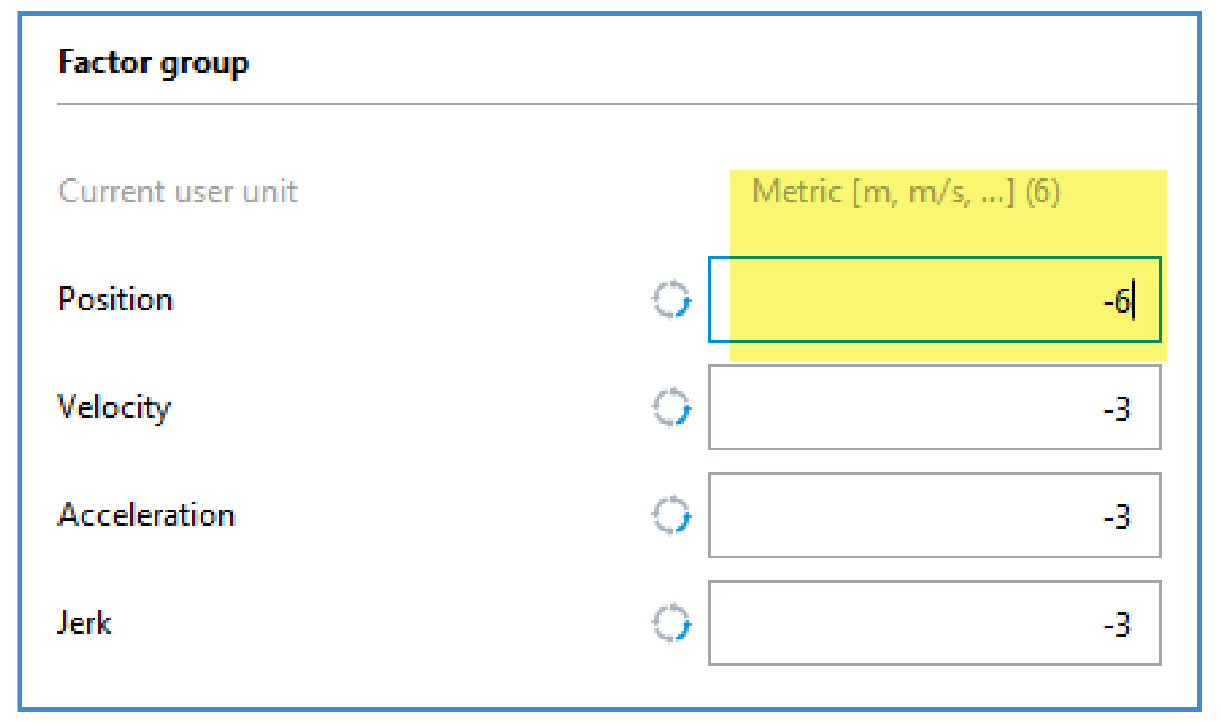
The settings in Festo Automation Suite and Sysmac Studio must match.
If you set the position index to -6 in FAS, set the command pulses per motor revolution to 1000 in Sysmac Studio.
“Work travel distance per motor rotation” can be used to set a higher resolution value than the Function Block.
In this example the value is 1. This means that the resolution of the set position of the Function Block is 1 mm (the value 100 in FB means 100 mm).
Next, set “Work travel distance per motor rotation” to 10, which gives a resolution of 0.1 mm (a value of 100 for FB means 10.0 mm).
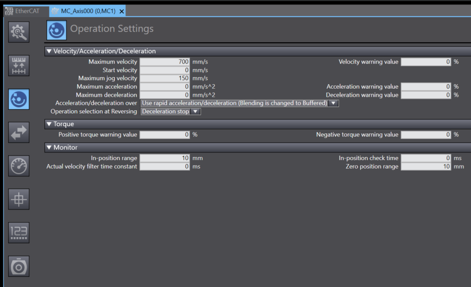
Operation Setting
This Operation Setting screen allows you to set speed, acceleration, deceleration, torque warning values and other monitoring parameters.
Set according to the application.
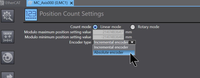
Position Count Settings
The Position Count Settings here set the controller’s count mode.

Set Encoder Type to Absolute encoder.
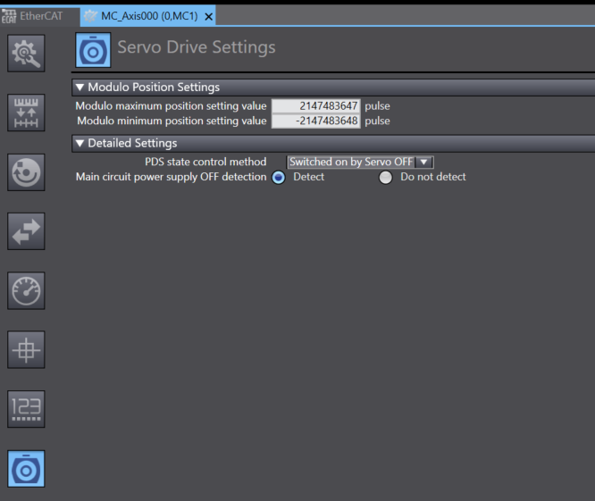
Servo Drive Settings
This Servo Drive Settings screen is used to set servo drive parameters.
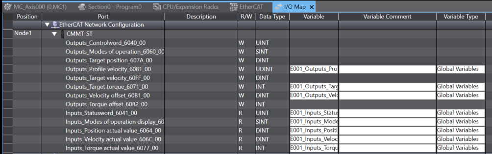
I/O Mapping
Now open the I/O Map and Mapping Process Data and Global Variables.
This is the Mapping screen in Sysmac Studio, and variables are automatically generated by right-clicking.
Program
Now create a programme.
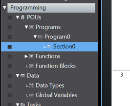
This is the programme created in this article.
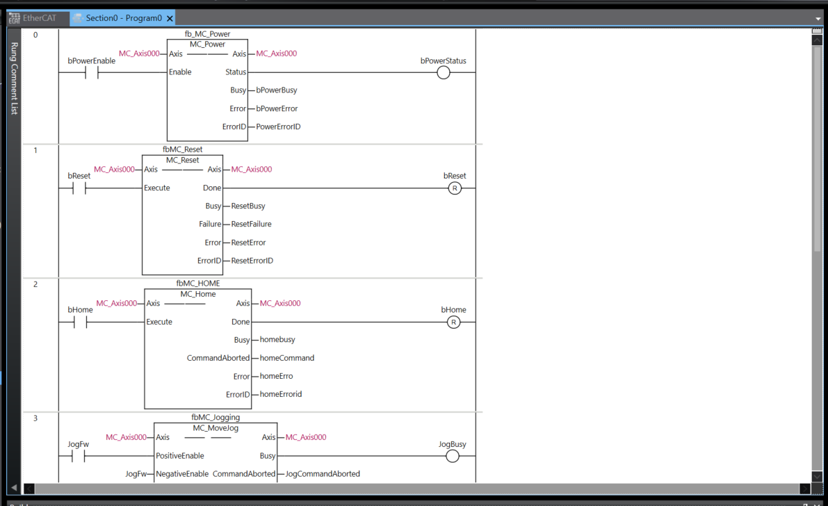
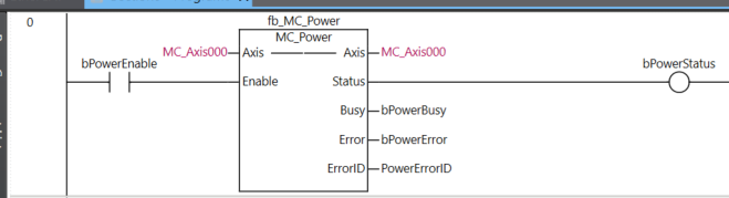
Rung0
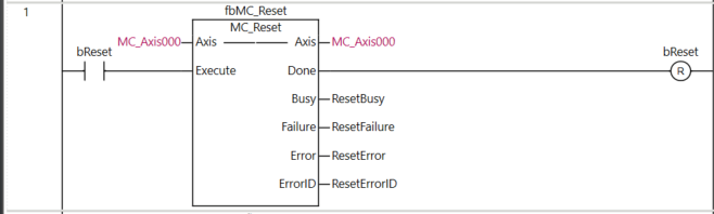
Rung1
Rung1 uses MC_Reset to reset Axis.
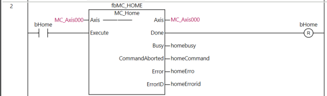
Rung2
Rung2 uses MC_Home to perform the Home Operation of Axis.
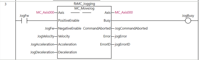
Rung3
Rung3 uses MC_Jogging to perform forward and reverse rotation of the Axis.
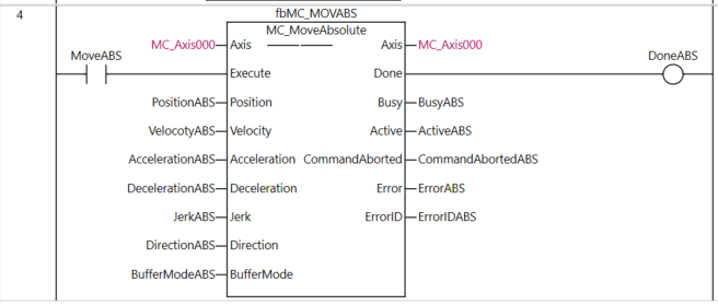
Rung4
Rung4 uses MC_MoveAbsolute to make absolute decisions on Axis.
Write Slave Address
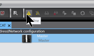
Next, use Sysmac Studio to write the Slave address to the EtherCAT Slave, click on Online and connect to the CPU.
Right-click on EtherCAT Master>Write Slave Node Address.
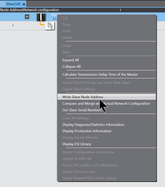
The Slave Node write screen is displayed.
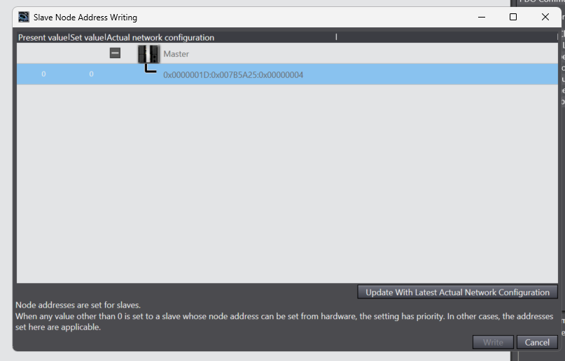
Set the address you want to write with Set Value and write the Slave address with the “Write” button.
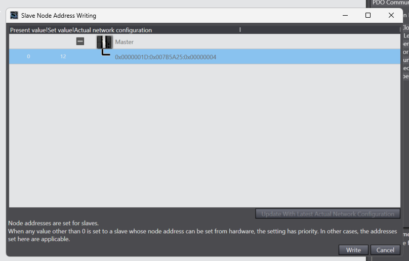
Proceed with Write.
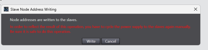
Done!
Download
Finally, download the project to the CPU.
Result
This video shows the operation of controlling a Festo Servo Drive from the OMRON CPU.