This article describes the procedure for setting up the Beckhoff safety controller EK1960 with TwinCAT. This article focuses on the initial construction of the safety project, and in the next article we will introduce FSOE communication and the connection of external safety IOs in due course. Please stay tuned for further developments!
Come on, let’s enjoy FA.
Foreword
Thank you from the bottom of my heart for visiting my technical blog and YouTube channel.
We are currently running the “Takahashi Chris” radio show with Full-san (full@桜 八重 (@fulhause) / X) which I deliver every Wednesday night.
Sharing, not hoarding, technical knowledge
We publish technical information related to factory production technology and control systems for free, through blogs and videos.
With the belief that “knowledge should be accessible to everyone,” we share practical know-how and real-world troubleshooting cases from our own field experience.
The reason we keep it all free is simple: to help reduce the number of people who struggle because they simply didn’t know.
If you’ve ever thought:
- “Will this PLC and device combination actually work?”
- “I’m having trouble with EtherCAT communication—can someone test it?”
- “I want to try this remote I/O, but we don’t have the testing environment in-house…”
Feel free to reach out!If lending equipment or sharing your configuration is possible, we’re happy to verify it and share the results through articles and videos.
(We can keep company/product names anonymous if requested.)
How can you support us?
Currently, our activities are nearly all unpaid, but creating articles and videos takes time and a proper testing environment.If you’d like to support us in continuing and expanding this content, your kind help would mean a lot.
Membership (Support our radio show)
This support plan is designed to enhance radio with Mr Full.
https://note.com/fulhause/membership/join
Amazon Gift List (equipment & books for content production)
Lists equipment and books required for content creation.
https://www.amazon.co.jp/hz/wishlist/ls/H7W3RRD7C5QG?ref_=wl_share
Patreon (Support articles & video creation)
Your small monthly support will help to improve the environment for writing and verifying articles.
https://www.patreon.com/user?u=84249391
Paypal
A little help goes a long way.
https://paypal.me/soup01threes?country.x=JP&locale.x=ja_JP
Just trying to share things that could’ve helped someone—if only they’d known.
Your support helps make knowledge sharing more open and sustainable.
Thank you for being with us.
soup01threes*gmail.com
Technical knowledge shouldn’t be kept to ourselves.
EK1960
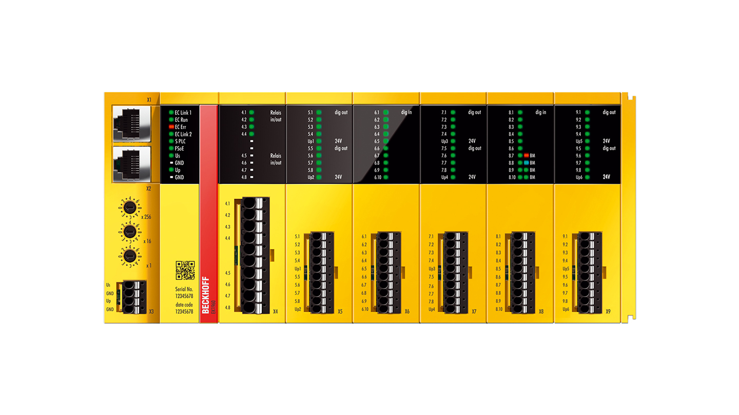
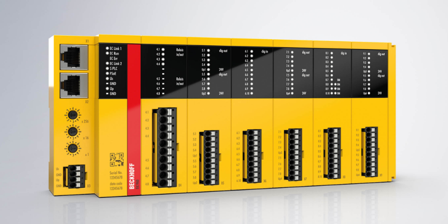
The EK1960 TwinSAFE compact controller is a device that maximises the application range of the TwinSAFE integrated safety solution. The safety controller core corresponds to the functions of the dedicated safety controller EL6910.
The compact design of the EK1960 with 20 safety digital inputs and 24 safety digital outputs (up to 2 A) covers the safety requirements of particularly compact machines.
The EK1960 can be operated ‘stand-alone’ or networked with other controllers via EtherCAT connectors.
When operating in an EtherCAT network, it can be extended with all EL/ES terminals in the same way as other EtherCAT couplers. For stand-alone devices, expansion by terminals is not possible.
The TwinSAFE Compact controller, like all TwinSAFE components, is programmed with the TwinCAT safety editor. Create a TwinSAFE project and load it into the EK1960 via EtherCAT.
Features
The EK1960 has the following features
- Analogue value processing
- Incremental downloading
- Diagnostic history directly on the component
- Up to 128 safety connections
- Up to 128 TwinSAFE groups
- Up to 40 users
- TwinSAFE SC support
- Stand-alone operation (without EtherCAT connection)
- 20 safe inputs
- 24 safe outputs
- 4 relay outputs (optional)
- Standard outputs can be activated by an integrated AND connection with the safety output signals
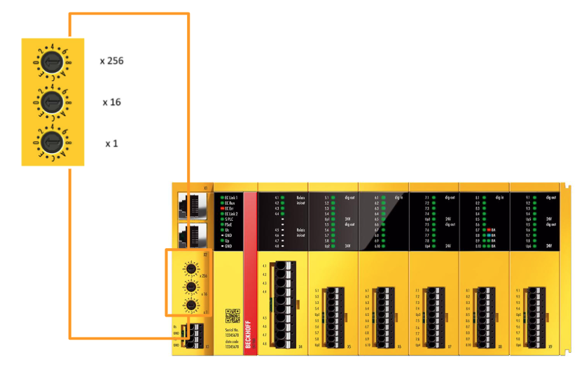
TwinSAFE address
The TwinSAFE address of the controller must be set using the three rotary switches on the housing of the EK1960 TwinSAFE controller The TwinSAFE address can be between 1 and 4095.
TwinSAFE?
The Beckhoff TwinSAFE product range enables the addition of safety components to Beckhoff I/O systems and the integration of safety circuits into existing fieldbus cables.
Safety signals can be mixed with standard signals if required. The transfer of safety-related TwinSAFE telegrams is handled by the standard controller. Maintenance is greatly simplified by quick diagnosis and easy replacement of components.
The TwinSAFE component includes the following basic functions
- Digital inputs (e.g. EL19xx, EP1908)
- Digital outputs (e.g. EL29xx)
- Drive components (e.g. AX5805)
- Logic units (e.g. EL6900, EL6910).
For many applications, complete safety sensor and actuator technology can be wired to these components. The necessary input and output logic links are also handled by the EL69xx. In addition to Boolean operations, the EL6910 also enables analogue operations.
Safety concept
In a nutshell, TwinSAFE is about integrating safety and I/O technology in one system. It is,
- Extend familiar Beckhoff I/O systems with TwinSAFE components
- Safe and unsafe components can be combined as required
- Logical linking of the I/Os of the EL69xx TwinSAFE logic terminals
- For applications up to SIL 3 according to EN 61508:2010 and Cat 4 according to EN ISO 13849-1:2015, PL e
- Safety-related networking of machines via bus systems
- In the event of an error, all TwinSAFE components are always switched to a Wattless, i.e. safe, state.
- No safety requirements for the higher-level standard TwinCAT system are required
Safety over EtherCAT protocol (FSoE)
FSoE supports TwinSAFE.
- Transfer of safety-relevant data via any media (“real black channel”)
- TwinSAFE communication via fieldbus systems such as EtherCAT, Lightbus, PROFIBUS, PROFINET and Ethernet
- Compliance with IEC 61508:2010 SIL 3
- FSoE is an IEC standard (IEC 61784-3-12) and an ETG standard (ETG.5100) Fail-safe principle (fail-stop)
The basic rule of safety systems such as TwinSAFE is that the failure of a component, system component or the entire system must never lead to a dangerous state. A safe state is always a switched-off, energisation-free state.
Safety conditions?
The safety status of all TwinSAFE components is always switched off.
Implementation
Preparing I/O devices
I/O device operations.
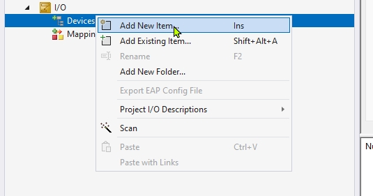
Right-click on ‘Devices’ in the I/O tree and select ‘Add New Item…’ and select ‘Add New Device…’ to prepare for adding a new device. This operation allows any communication protocol device, such as EtherCAT or Profinet, to be added to the TwinCAT project.
Device type selection
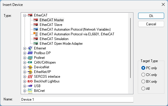
The ‘Insert Device’ dialogue opens, allowing the user to select the communication protocol for the device to be used. In this case, “EtherCAT Master” is selected. On the right-hand side, the target device type (PC/CX/BX etc.) can also be selected.
Selecting a network adapter
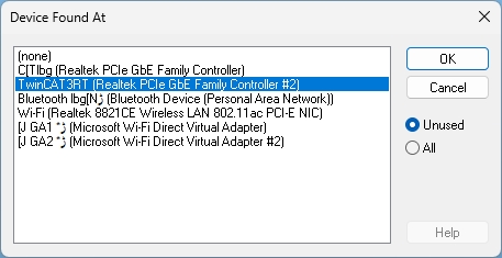
A screen for specifying the network adapter to be used by TwinCAT is displayed, listing several NICs (network interface cards). By selecting the adapter with the ‘TwinCAT3 RT (Real-Time)’ Driver installed, a configuration is established that enables real-time control.
Scanning operation of EtherCAT devices.
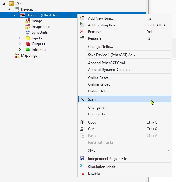
By right-clicking on ‘Device 1 (EtherCAT)’ and selecting ‘Scan’, a process is executed to automatically detect all connected EtherCAT slave devices. This automatically takes the configuration of each physically connected terminal into TwinCAT.
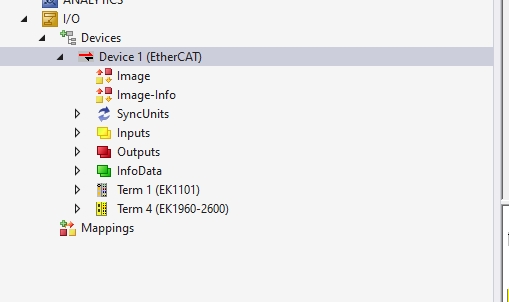
Check I/O configuration after scanning
As a result of the scan, the actually connected terminals such as “Term 1 (EK1101)” and “Term 4 (EK1960-2600)” are automatically added under Device 1 (EtherCAT). This allows the programme to be configured on TwinCAT in a state that matches the actual device configuration.
PLC Project
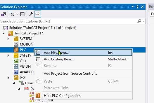
Add PLC Project
Right-click ‘PLC’ in the Solution Explorer and select ‘Add New Item…’ to add a project for describing the PLC control logic.
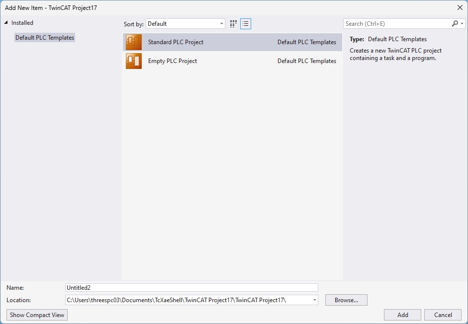
A screen is displayed for creating a TwinCAT PLC project by selecting from the ‘Standard PLC Project’ or ‘Empty PLC Project’ templates. If Standard is selected, the initial configuration is automatically added.
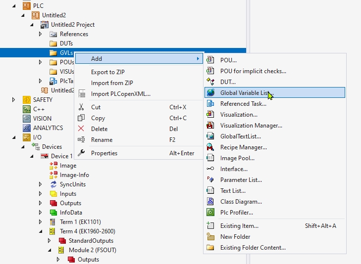
Addition of Global Variable List (GVL)
You are about to add a global variable list by right-clicking on ‘GVLs’ in the PLC project and selecting ‘Add > Global Variable List’. This will enable the definition of a group of variables that can be used throughout the PLC.
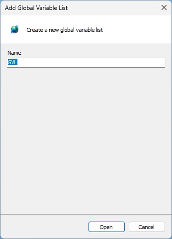
A dialog box for creating a new GVL (Global Variable List) is displayed, and the default name “GVL” is entered. If “Open” is clicked at this point, the new GVL is created and can be used in the project.
The global variables xRun and xError are defined in GVL. Each variable is mapped to a physical I/O address as %Q* (output).
| {attribute ‘qualified_only’} VAR_GLOBAL xRun AT %Q*:BOOL; xError AT %Q*:BOOL; END_VAR |
Project Build
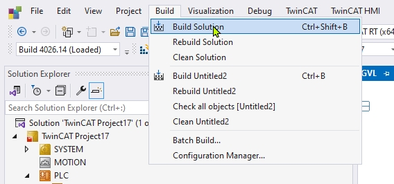
From the “Build” menu, “Build Solution” is selected. This will compile all projects, check for syntax errors and perform the linking process for the generated code.
PLC Configuration Activation
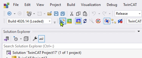
By pressing Activate Configuration in the figure below, you activate the configuration of the entire TwinCAT system.
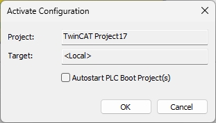
The name of the project to be activated and the target (usually <Local>) will be displayed.
If necessary, “Autostart PLC Boot Project(s)” can also be checked for automatic activation settings.
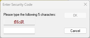
When TwinCAT’s license for the system has expired, entering the confirmation characters (5 characters) will authorize the license to become most valid.
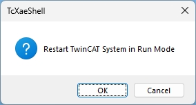
You will be asked, “Do you want to reboot the TwinCAT system in Run mode?” When asked, press “OK” to begin reflection.
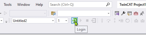
After activating the configuration, press the button to log into the PLC program and switch the project status to online.
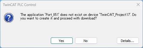
Proceed with Yes.
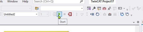
Finally, the Start button executes Runtime.
Building a Safety Project
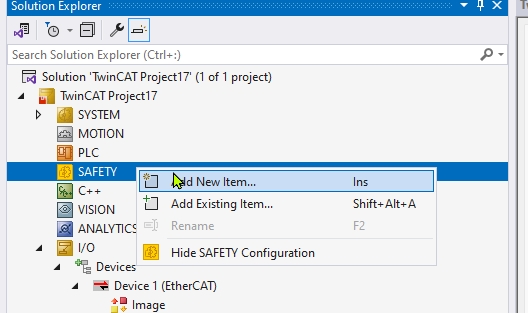
Add a new Safety project with SAFETY>Add New Item.
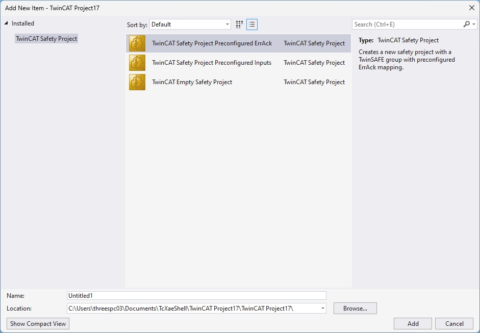
In the “Add New Item” dialog, several templates for the TwinCAT Safety Project are displayed, allowing the user to select a configuration for error message response (Preconfigured ErrAck) or an input preset configuration. In this case, the project is generated based on the template for error message response (Preconfigured ErrAck).
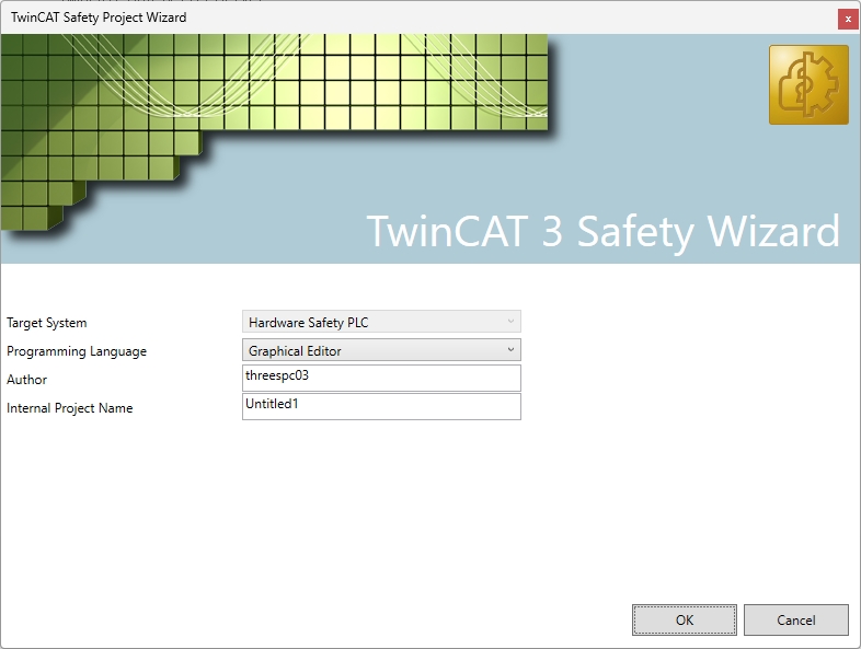
The TwinCAT Safety Wizard setup screen appears, where the target system (Hardware Safety PLC), programming language to be used (Graphical Editor), creator name, and project name are entered. After completing the settings on this screen, the project is created.
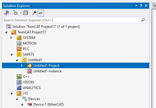
A TwinCAT Safety project called “Untitled1” has been created, and in addition, the “Untitled1 Project” and its instances are displayed. The I/O section also shows a scanned “Device 1 (EtherCAT)”, confirming that safety control and normal I/O are configured in parallel.
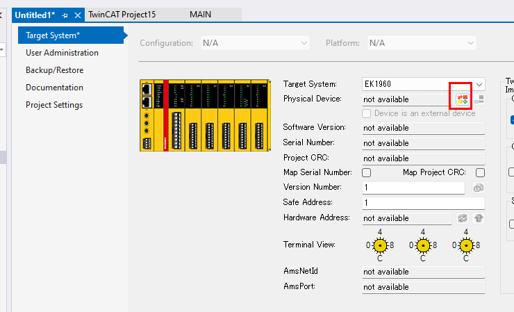
Configure Target System
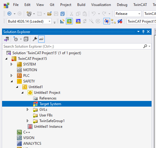
Click Target System.
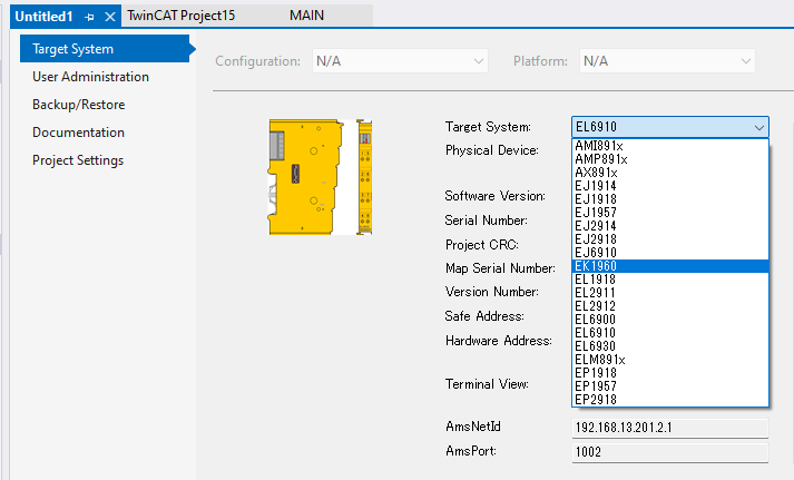
The “Target System” configuration window opens, and in the “Physical Device” column on the right side, the type of EtherCAT terminal can be selected. The choices include a line of Safety terminals made by Beckhoff, and in this case the EK1960 is selected.
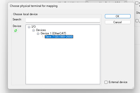
To connect the logical configuration and the actual EtherCAT device, click on the button with the red frame, and the window “Choose physical terminal for mapping” will appear. Here “Device 1 (EtherCAT)” is found as the recognized EtherCAT device and “EK1960” under it is selected. By selecting this, the logical configuration is linked to the actual hardware.
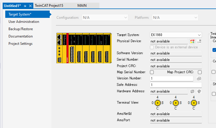
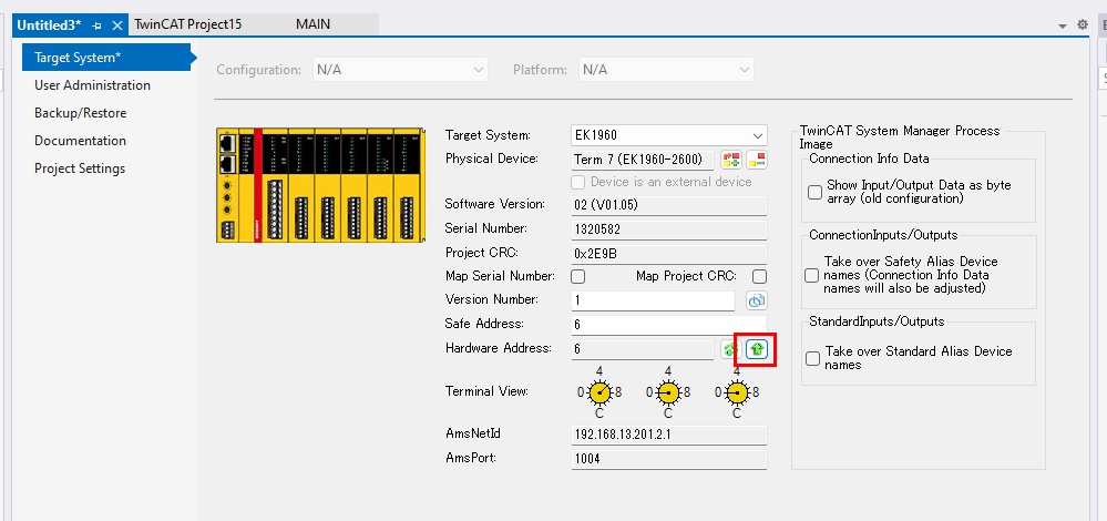
Once the mapping to the actual device is complete, the configuration screen automatically reflects the serial number, hardware address, version number, and other information. The “Term 2 (EK1960-2000)” is now connected, and the configured I/O modules are also visually displayed. In this state, it can be confirmed that the actual device and TwinCAT settings match.
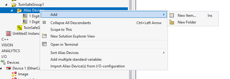
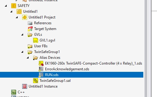
New entry added to Alias Devices
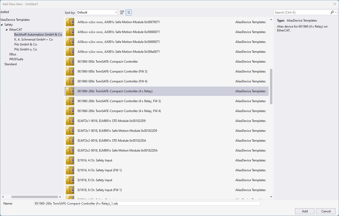
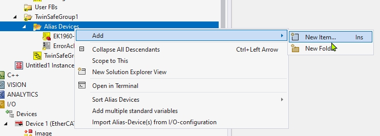
Right click on “Alias Devices” under TwinSafeGroup1, and from the menu “Add” -> “New Item…” The operation to select “New Item…” is displayed.
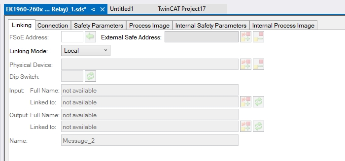
From the list of templates displayed, select a pre-existing alias such as “EK1960-260x TwinSAFE-Compact-Controller (4 x Relay)”.
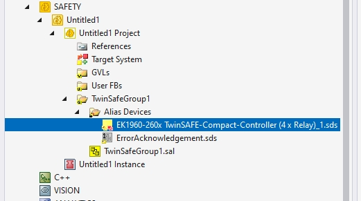
Done!
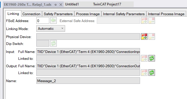
From the “Linking Mode” pull-down menu, you can select “Automatic,” “Manual,” or “Local” to switch the linking method according to your application. In this case, set “Local” since the EK1960’s local IO will be used.
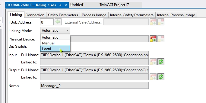
When set to Local, all physical device information for inputs and outputs will be set to “not available”. That is OK.
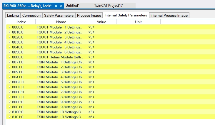
In the “Internal Safety Parameters” tab, safety parameters for each module, such as FSOUT and FSIN, can be viewed. An index is assigned to each configurable channel, and each configuration can be edited. Since this is the first episode, we will not configure any particular settings.
Adding a new Alias Device
Right-click on “Alias Devices” and select “Add > New Item…” to add another Alias Device (e.g., digital input or output).
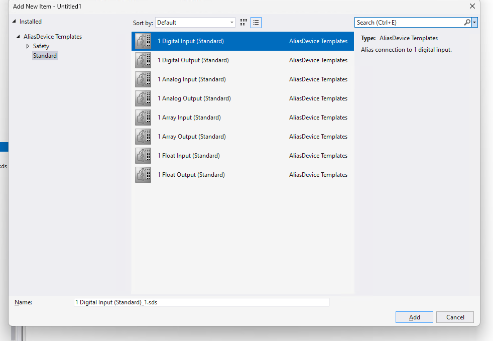
The template selection screen appears and “1 Digital Input (Standard)” is selected. This is an alias device to simulate a standard single digital input, which can be freely used for connections within TwinSAFE.
Done!
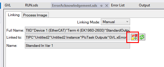
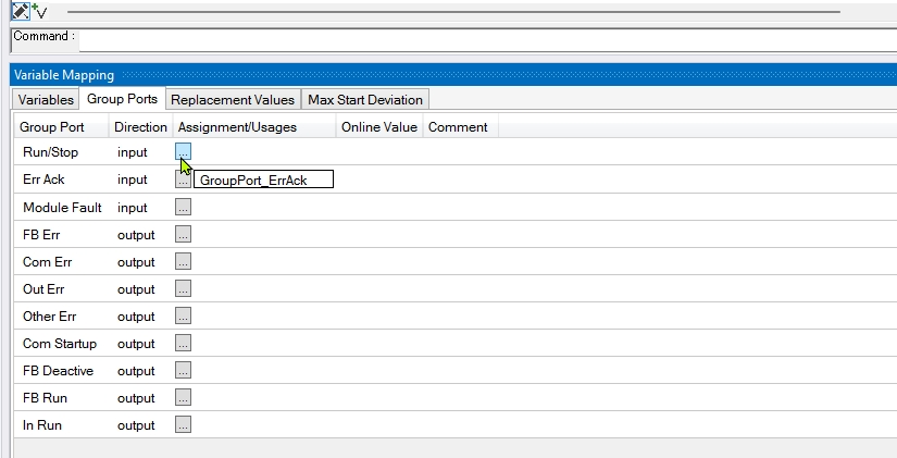
Within the Group Port Settings tab, you can specify the signal name to assign (e.g., GroupPort_ErrAck) for signal lines such as “Run/Stop” or “Err Ack (error acknowledgement)” By pressing the Variable Connection button in the ErrorAcknowledgement.sds It can be mapped to variables in the PLC project.
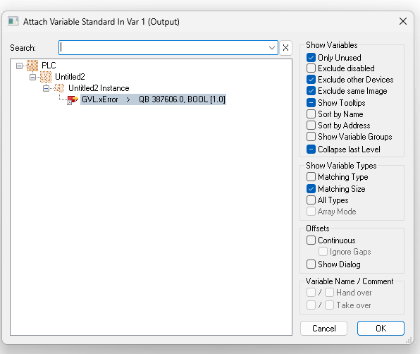
In the “Attach Variable” window, the GVL.xError variable in the PLC project Untitled2 is displayed, indicating that it is ready to connect to the TwinSAFE device.
Add GVL
Right click on the “GVLs” section of the SAFETY project and select “Add > Global Variable List…” to prepare to define global variables in the TwinSAFE project.
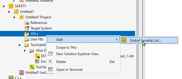
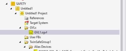
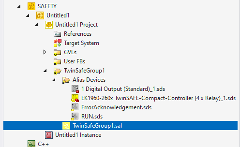
You can see that a new GVL file has been created with the name “GVL1.sgvl”. This will allow centralized management of variables used within the safety logic.
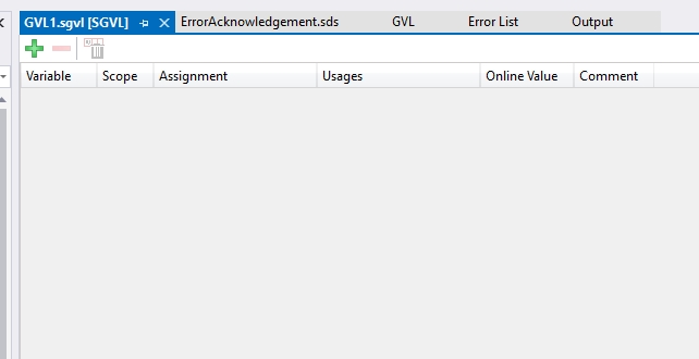
The contents of the newly created GVL1.sgvl are displayed, but no variables are defined yet. Here, safety-related variables such as BOOL types should be defined and made available to the logic in the TwinSAFE editor.
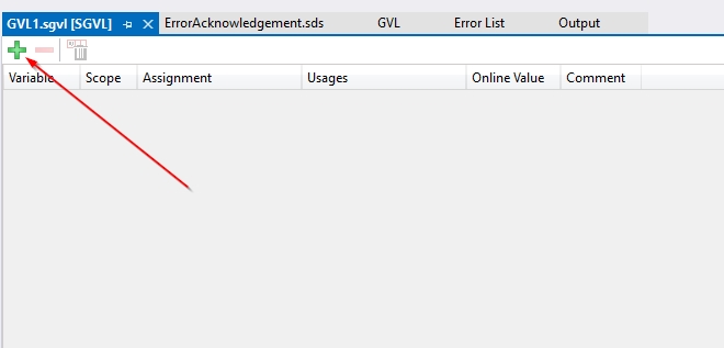
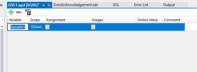
On the edit screen of GVL1.sgvl, the operation of adding a new global variable (e.g. RUN) for TwinSAFE by pressing the “+” icon in the upper left corner of the screen.
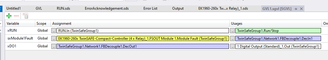
Three variables are defined on the screen:
- xRUN (system start/stop control)
- sxModule1Fault (module fault detection)
- xDO1 (digital output 1)
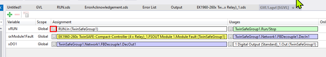
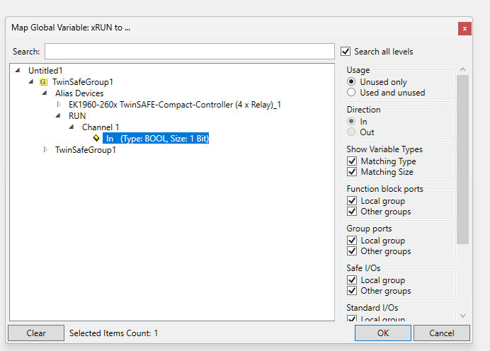
Select the appropriate input channel for the xRUN variable.
Set the RUN defined earlier.
TwinSAFE Group
Next, open TwinSAFEGroup.
Within the Group Port Settings tab, you can specify the signal name to be assigned (e.g., GroupPort_ErrAck) for signal lines such as “Run/Stop” and “Err Ack (error confirmation)”.
Safety Program
The next step is to create a safety program.
Validation operations for Safety projects
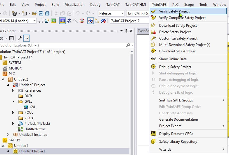
Click TwinSAFE→Verify Safety Project to check for the presence of syntactic and logical errors (e.g., unlinked connections, undefined variables, etc.) in the TwinSAFE safety project. This is an essential step to ensure the integrity of the safety function after changes have been made to the project.
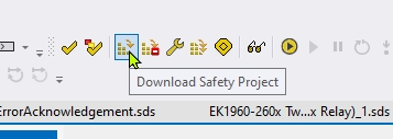
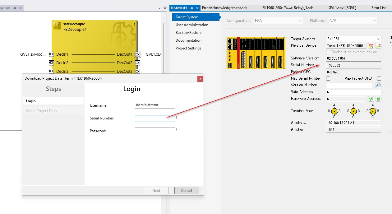
The “Download Safety Project” button at the top of the screen is selected to write the safety logic to the device.
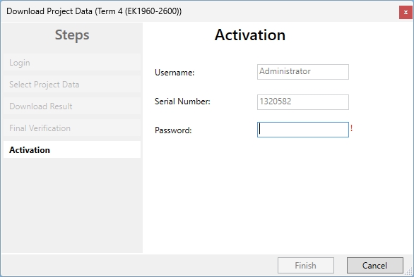
The device serial number and password are required at the time of download. Confirm the corresponding serial number (e.g., 1320582) in the EK1960 Settings field on the right side of the screen and enter it in the login form on the left side.
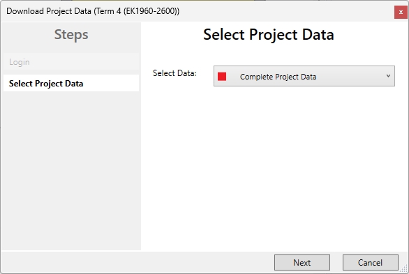
In the “Select Project Data” screen, select “Complete Project Data” and proceed to the next step to transfer the complete logic and mapping data.
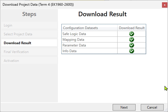
In the “Download Result” screen, a green check indicates that all of the following data has been successfully downloaded:
- Safe Logic Data
- Mapping Data
- Parameter Data
- Info Data
In the “Download Result” screen, a green check indicates that all of the following data has been successfully downloaded:
- Safe Logic Data
- Mapping Data
- Parameter Data
If all items have check marks, the project data is normal.
Check the checkboxes at the bottom and click “Next.
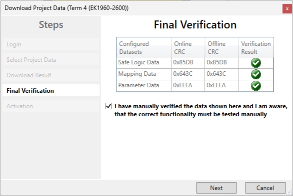
Next is the login screen to activate (Activate) the downloaded safety logic.
- Serial Number is automatically entered (e.g., 1320582)
- Password is the password for the TwinSAFE project.
Finally, click “Finish” to proceed to activation.
result
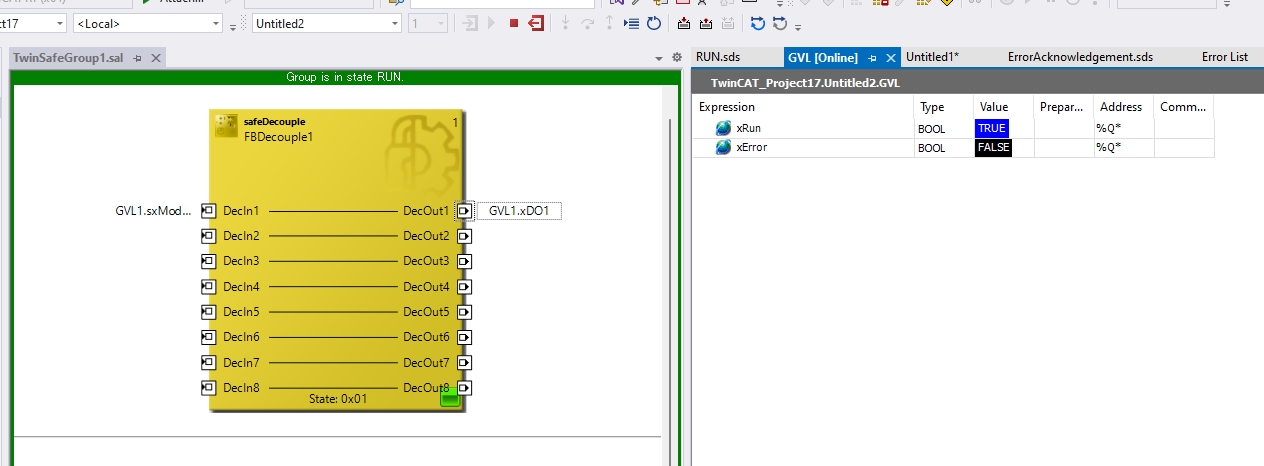
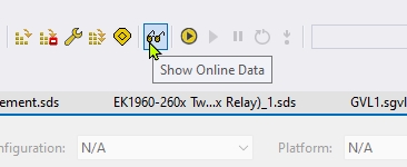
The Show Online Data button allows real-time monitoring of the status of FBs and alias devices. It is used for debugging confirmation that the safety project is working properly.
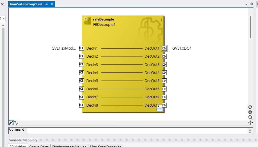
So the blue strip at the top of the screen says “Group is in state STOP,” indicating that it is not yet in RUN state. The state of each DecOut (output) is STOP (e.g., shown in red) and the safety block (FB) is waiting.
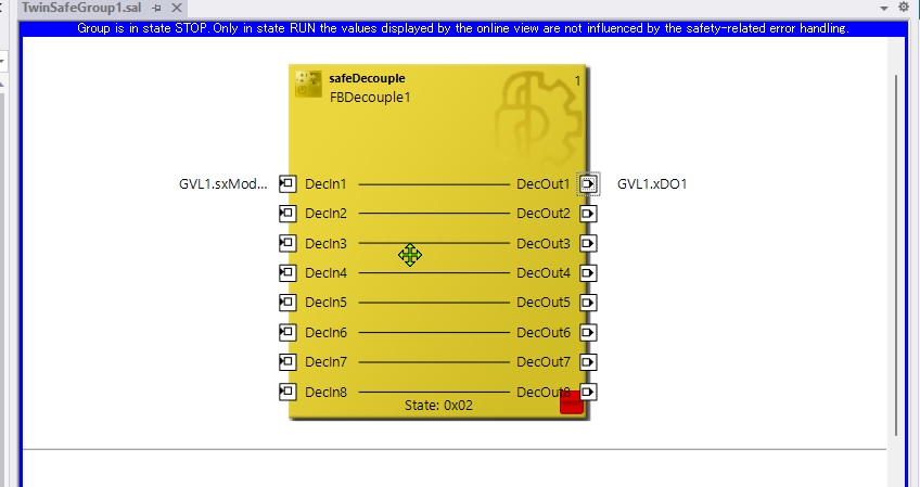
First, the value of the TwinCAT PLC variable xRun is TRUE: This is the input signal to put the TwinSAFE group in the running state (RUN).
- The TwinSAFE side is receiving the RUN command (xRun) from the PLC normally, and there is no abnormality in xError.
- The green band at the top of the screen says “Group is in state RUN.”, clearly indicating that the TwinSAFE group itself is in the RUN state.