In this tutorial,we take a look at the “safeEdm” safety block that can be used with Beckhoff TwinSAFE and explain the basics of emergency stop button monitoring (EDM) and diagnostic pulse and input filter settings.
How do you prevent EDM errors?” What is b-time?” will be explained using actual TwinCAT screens and diagrams. This will help you to understand the mechanism of diagnostic pulse timing settings, which may seem a bit complicated, and should help you to sort them out.
Now, let’s enjoy FA!
Foreword
Thank you from the bottom of my heart for visiting my technical blog and YouTube channel.
We are currently running the “Takahashi Chris” radio show with Full-san (full@桜 八重 (@fulhause) / X) which I deliver every Wednesday night.
Sharing, not hoarding, technical knowledge
We publish technical information related to factory production technology and control systems for free, through blogs and videos.
With the belief that “knowledge should be accessible to everyone,” we share practical know-how and real-world troubleshooting cases from our own field experience.
The reason we keep it all free is simple: to help reduce the number of people who struggle because they simply didn’t know.
If you’ve ever thought:
- “Will this PLC and device combination actually work?”
- “I’m having trouble with EtherCAT communication—can someone test it?”
- “I want to try this remote I/O, but we don’t have the testing environment in-house…”
Feel free to reach out!If lending equipment or sharing your configuration is possible, we’re happy to verify it and share the results through articles and videos.
(We can keep company/product names anonymous if requested.)
How can you support us?
Currently, our activities are nearly all unpaid, but creating articles and videos takes time and a proper testing environment.If you’d like to support us in continuing and expanding this content, your kind help would mean a lot.
Membership (Support our radio show)
This support plan is designed to enhance radio with Mr Full.
https://note.com/fulhause/membership/join
Amazon Gift List (equipment & books for content production)
Lists equipment and books required for content creation.
https://www.amazon.co.jp/hz/wishlist/ls/H7W3RRD7C5QG?ref_=wl_share
Patreon (Support articles & video creation)
Your small monthly support will help to improve the environment for writing and verifying articles.
https://www.patreon.com/user?u=84249391
Paypal
A little help goes a long way.
https://paypal.me/soup01threes?country.x=JP&locale.x=ja_JP
Just trying to share things that could’ve helped someone—if only they’d known.
Your support helps make knowledge sharing more open and sustainable.
Thank you for being with us.
soup01threes*gmail.com
Technical knowledge shouldn’t be kept to ourselves.
Reference Link
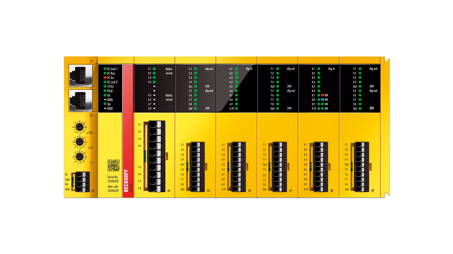
terminal block (electrical)
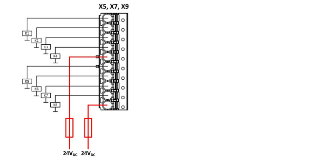
Digital output X5, X7, X9
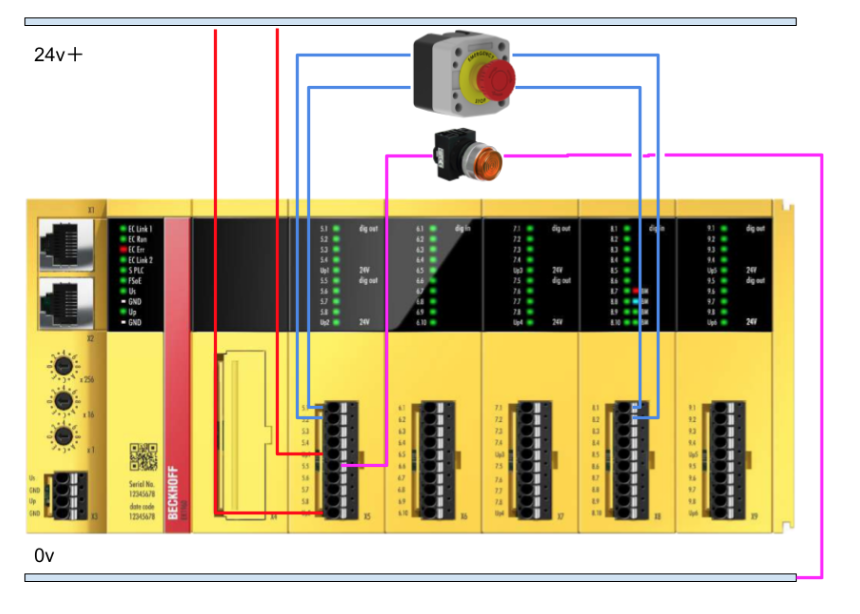
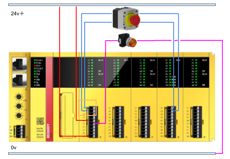
Connections X5, X7, and X9 require 24 VDC to be supplied to contacts 5 and 10. These provide 4 outputs each. The connected actuators are not fed back to the EK1960 and are wired directly to GND.
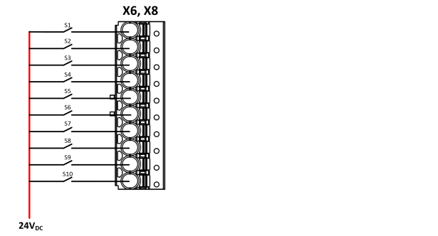
Digital inputs X6, X8
The digital inputs are supplied with a 24 VDC signal. Static or clock signals are supported in the default configuration. The safety output of the EK1960 can also be selected as a clock signal source.
What is a test pulse?
Beckhoff’s EK1960 (TwinSAFE controller) periodically checks (diagnoses) outputs and inputs for corruption in order to increase safety. The diagnostics are based on a brief signal called a “test pulse” that is used to check the outputs and inputs.
Where are they being used?
Beckhoff’s EK1960 (TwinSAFE controller) is used at
- Output (FSOUT): For example, relay or transistor output
- Input (FSIN): e.g., sensor or E-Stop button signal
How does it work?
For one channel of output module:
For one channel of the output module, the feedback test is done four times, i.e., four diagnostic pulse tests (the number of times depends on the set value), resulting in about 20 ms per channel, or 80 ms for four channels. Note that the relay module is special and is calculated to take about 250 ms per channel.
For input (FSIN):.
One channel has a diagnostic cycle of 2 ms, multiplied by a factor of 1.25, so about 2.5 ms × 10 channels ≈ 25 ms
Total time required
As an example of the time it takes for the diagnostic process to complete one round (= b hours),
- 6 output modules x 80ms = 480ms
- 1 relay module = 250ms
- Diagnostics for 10 input channels = 25 ms
- Total approx. 755ms
This means that the EK1960 can take up to 755 ms to diagnose one round.
Issue?
Even if the sensor signal “changes momentarily” during this time, it may not be read because it was in the middle of a diagnostic pulse. For example,
- E-Stop was pressed but not detected
- Malfunction in EDM (Error is generated)
This can lead to problems such as
Solution?
To prevent this problem, the following measures are available
| counter-measure | Description |
| Turn off DiagTestPulse. | When the input requires a fast response (no diagnosis) |
| Adjust the value of ModuloDiagTestPulse. | Slow down the test cycle a little. |
| Switch On/Off Monitoring longer time | To absorb timing errors in EDM |
EDM
FB EDM is a TwinSAFE functional block intended for ‘external device monitoring’.
It monitors the temporal relationship between input signals Mon1 and Mon2.
- Switch-on monitoring
- Switch-off monitoring
It is important to note that both are disabled by default, so at least one of them must be enabled.
Switch-on Monitoring
Switch-on monitors the following items, for example, in applications such as ‘making sure the feedback contact is switched off’ on a safety relay.
- After Mon1 changes from 0 to 1
- Whether Mon2 is set to 0 or not within a specified time (max. 10,000 ms).
- within the specified time (max. 10,000 ms).
Switch-off Monitoring
Switch Off monitors the following items and can be used, for example, to check whether the “auxiliary contacts have been switched on” when switching from ON to OFF.
- After Mon1 changes from 1 to 0,
- Whether Mon2 is set to 1 or not.
- Similarly, check within the specified time (max. 10,000 ms).
Error conditions
Errors occur in safeEdm under the following conditions.
- If the time set for switch-on or switch-off is exceeded and there is still no suitable signal, the FB EDM will enter the FbError state.
The output Error then becomes TRUE. This error can only be cleared by acknowledgement (acknowledgement) with the ERR_ACK signal.
input
| Name | Data Type | Content Description |
| Mon1 | BOOL (TwinSAFE-In) | 1st input. Usually parameterisable as break contact (NC) or make contact (NO). |
| Mon2 | BOOL (TwinSAFE-In) | Second input. The opposite value of input 1 must be taken within the specified time. |
output
| Name | Data Type | Content Description |
| Error | BOOL (TwinSAFE-Out) | TRUE: ON/OFF switching time has timed out (error); FALSE: No error; |
Implementation
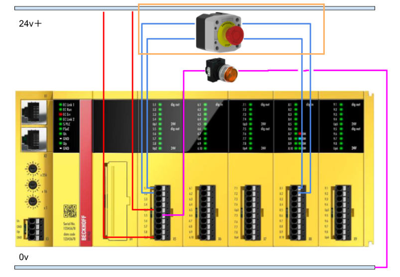
Wiring
This is the wiring for this article.
safety parameter
Click TwinSafeGroup1>Alias Devices>Ek1960 to set the safety parameters for the EK1960-260x.
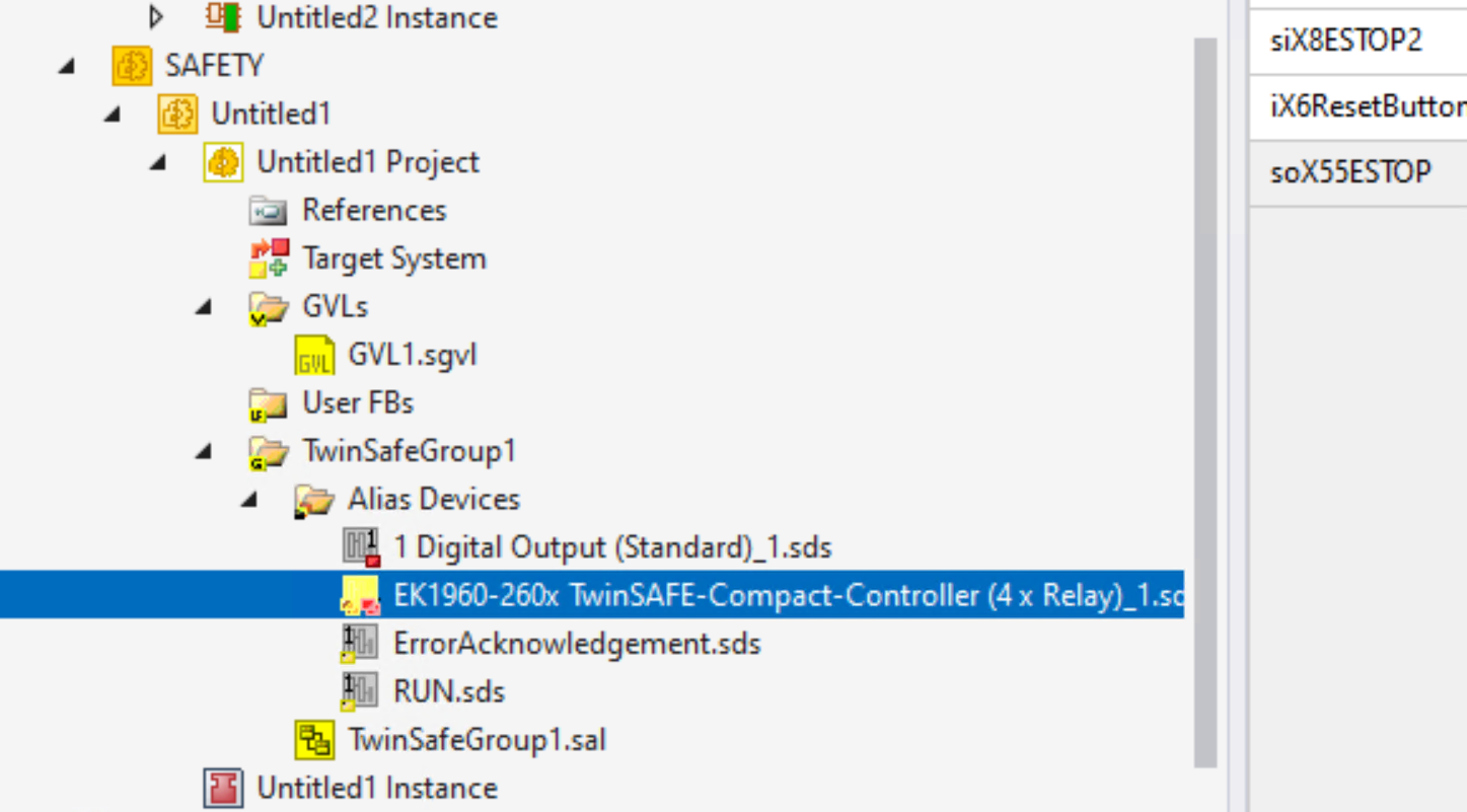
Here you can access and adjust the detailed set values of the respective FSIN (safety input) and FSOUT (safety output) modules.
ESTOP
First set the parameters relating to the emergency stop wired to the Ek 1960.
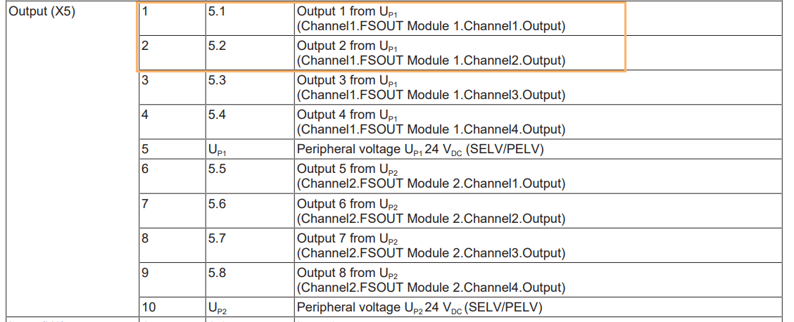
Terminals X5-5.1 and 5.2
First set terminals X5 5.1 and 5.2 as test pulses.
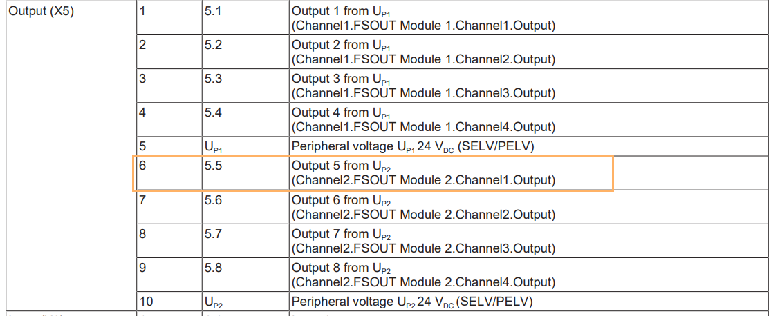
From the EK1960 instruction manual, OutputX5 5.1 and 5.2 are described as FSOUT.Module.1.Channel.Output.
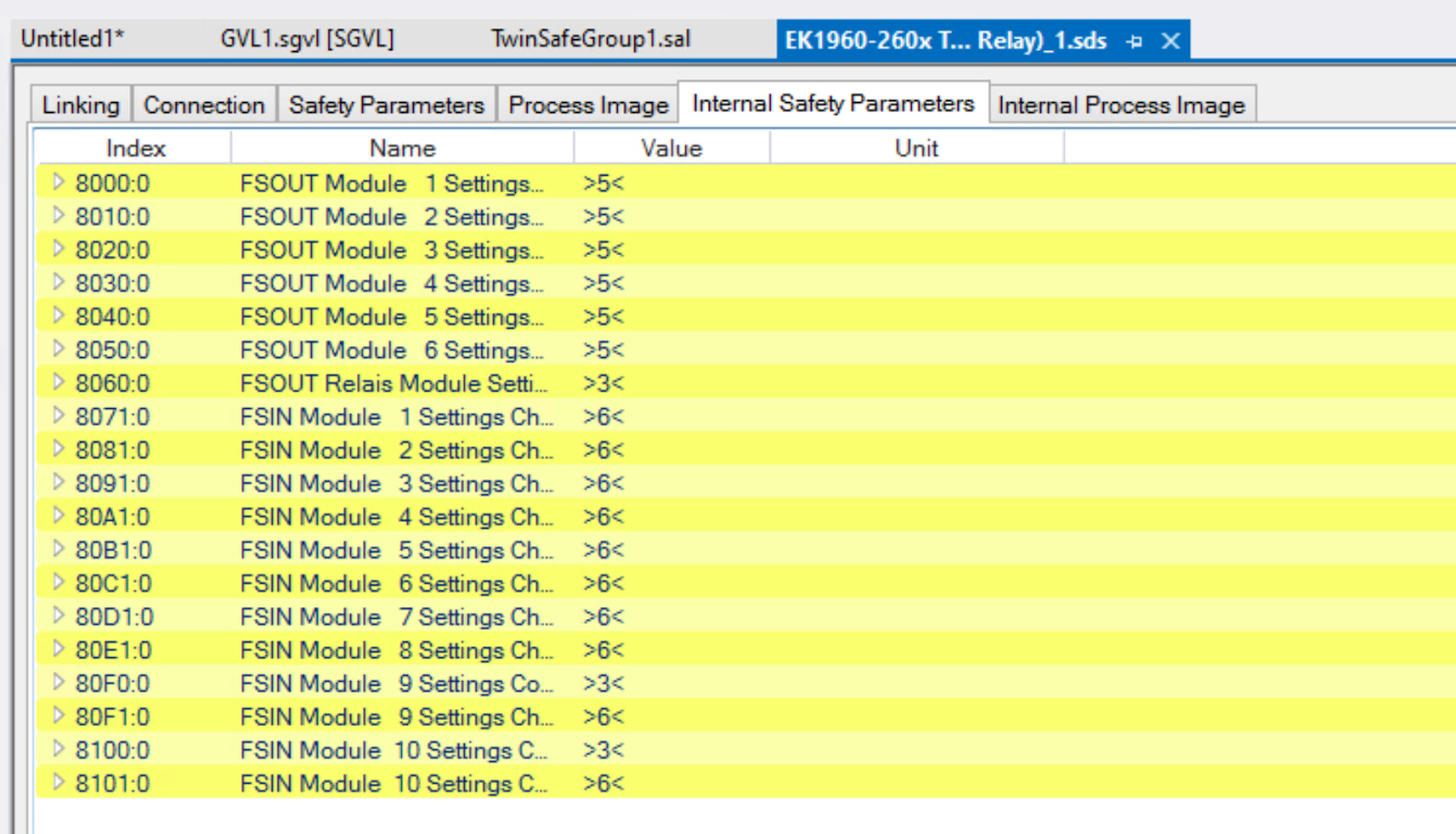
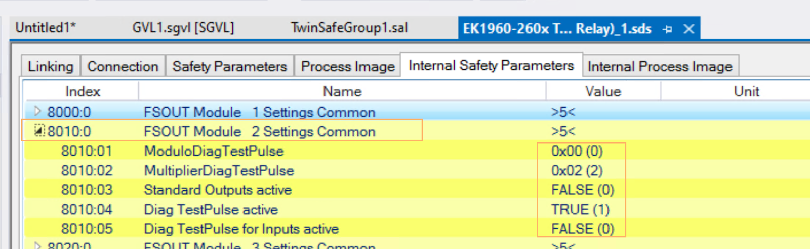
Open the Internal Safety Parameters tab and 8000:00 is the basic setting for FSOUT Module 1.
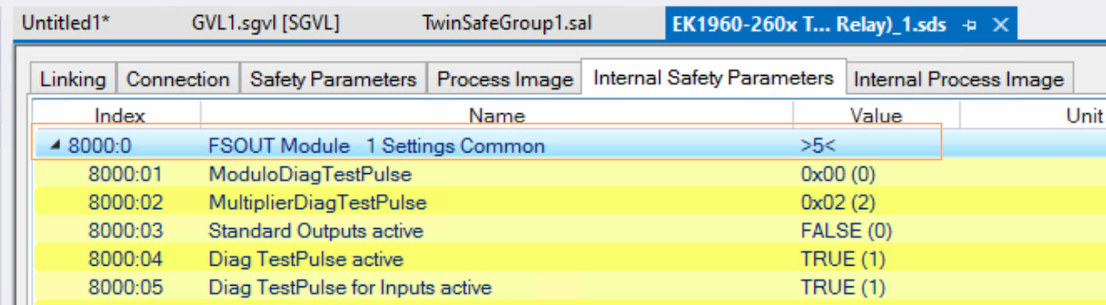
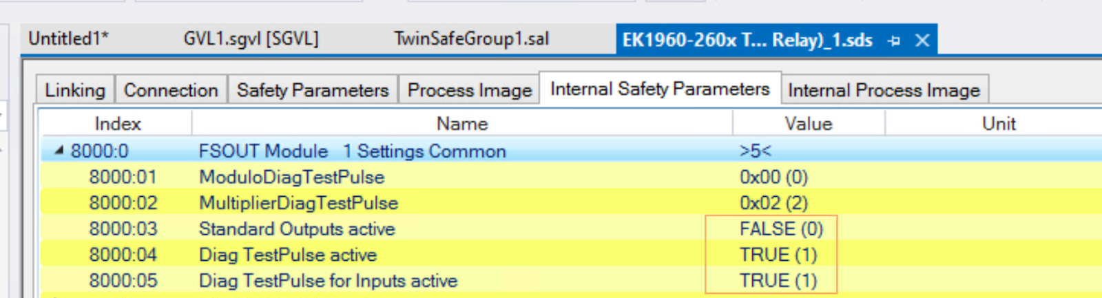
Then set Standard Output Active to FALSE and both Diag TestPulse active and Diag TestPulse For Inputs Active to TRUE.
Meaning of parameters
| Index | Description | DEFAULT |
| ModuloDiagTestPulse (80x:01) | Clock frequency of the test. 0 = every time. | 0 |
| MultiplierDiagTestPulse (80x:02) | Pulse length multiplier. 1 = 400 µs, 2 = 800 µs… | 2 |
| Standard Outputs active (80x:03) | Whether standard signals are used for outputs | FALSE |
| Diag TestPulse active (80x:04) | Use test pulses on the output side or | FALSE |
| Diag TestPulse for Inputs active (80x:05) | Use this output to diagnose the input or | FALSE |
| Module Fault Link active (80x:07) | If this module fails, do other modules also fail? | TRUE |
Terminals X8-X8.1 and X8.2
The next step is to set the safety inputs X8.1 and X8.2, which receive the emergency stop signal.

According to the instruction manual, X8.1 and X8.2 are Channel13.FSIN.Module6.ChannelX.Input.
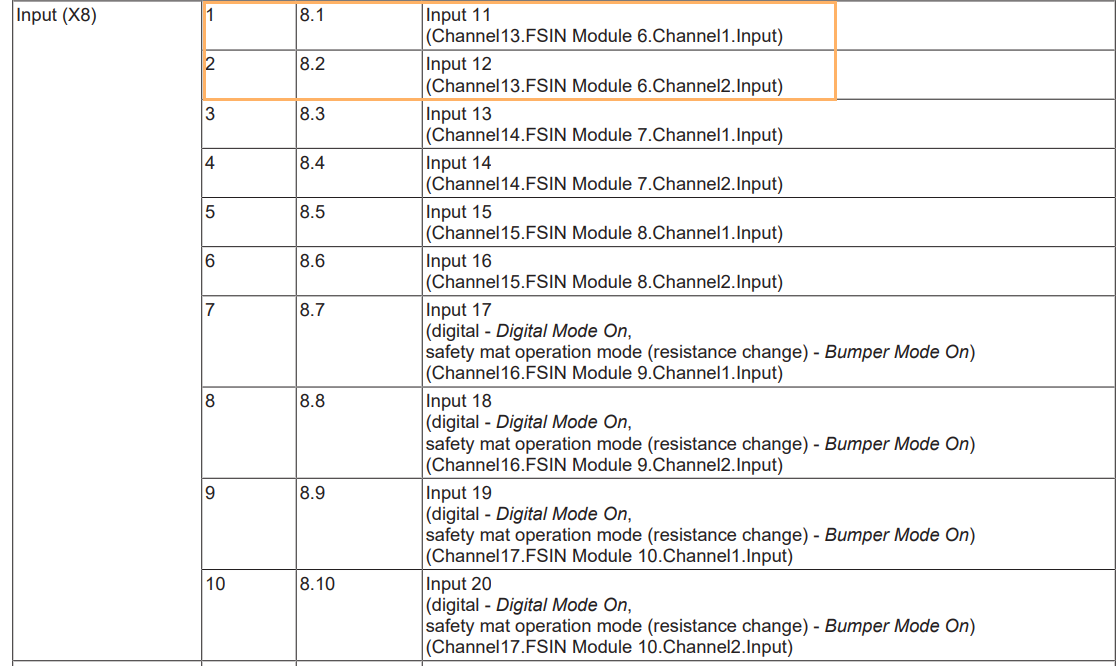
So 80C1 is the relevant setting.
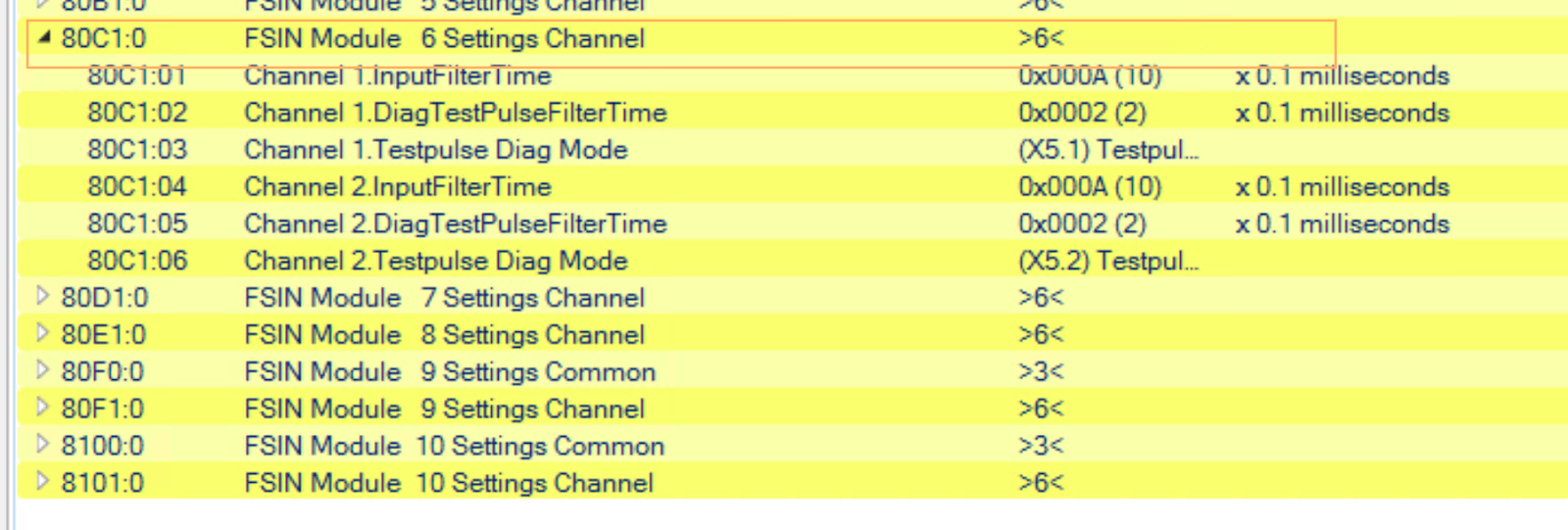
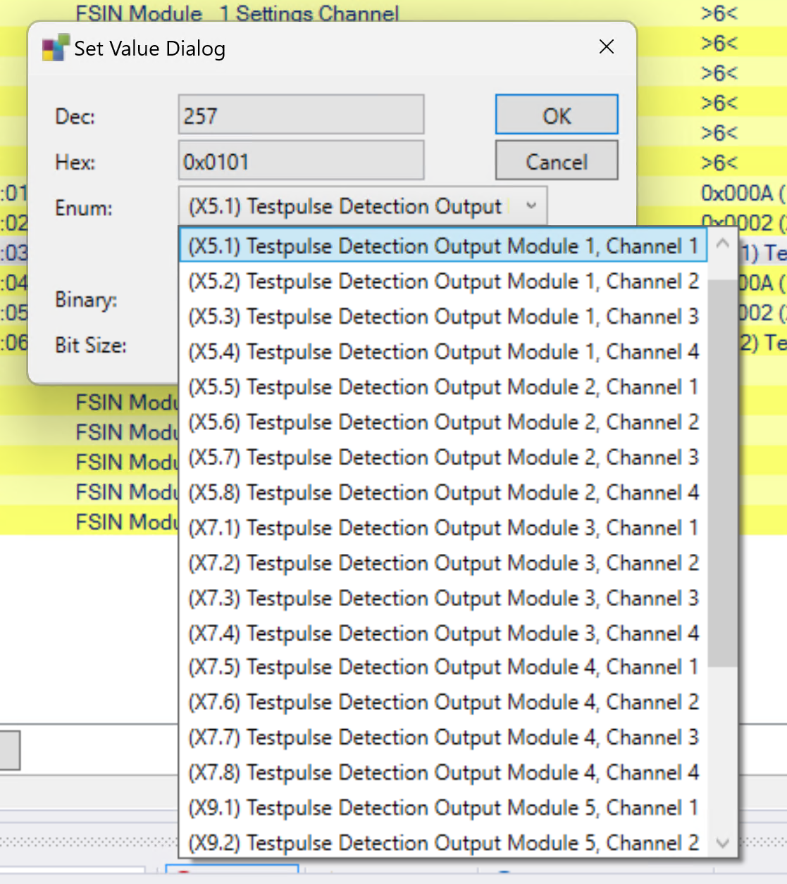
80C1:03 and 80C1:06 are the mode settings for the test pulse.
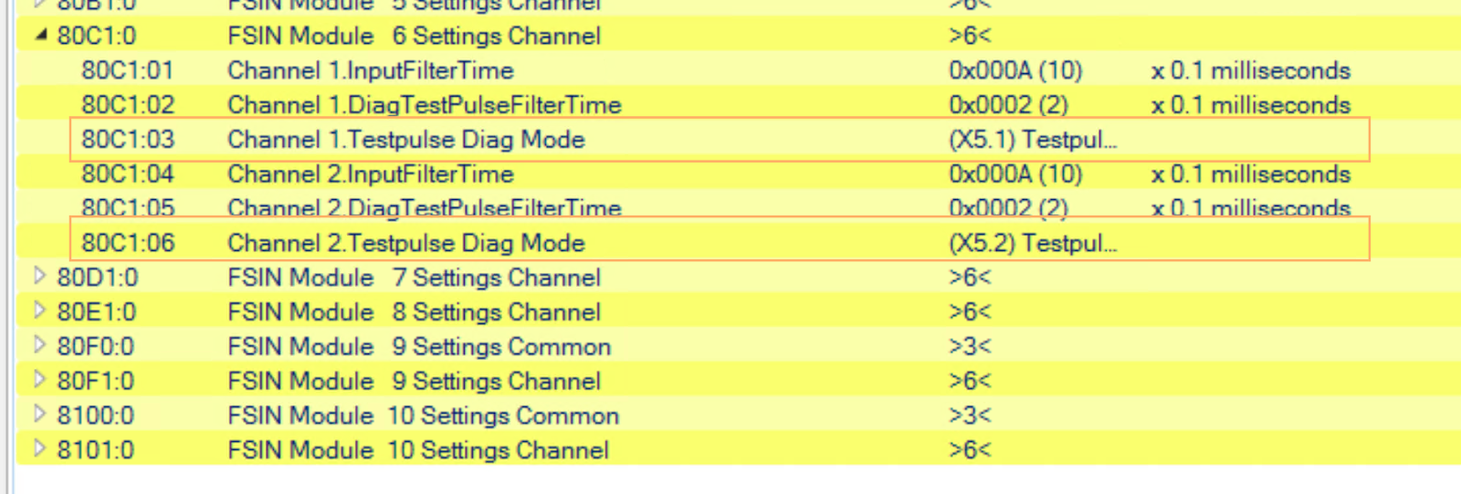
Double-click 80C1:03 and 80C1:06 to display the Set value Dialog screen.
The source of the test pulses can be set from Enum.
Meaning of parameters
| Index | Description | Current value |
| 8071:01 | Channel 1 input filter time in 100 µs | 10(=1ms) |
| 8071:02 | Filter time for Channel 1 test pulse diagnostics (in 100 µs increments) | 3(=300µs) |
| 8071:03 | Which output channel Channel1 receives pulses from | External Testpulse |
| 8071:04 | Channel 2 input filter time in 100 µs | 10(=1ms) |
| 8071:05 | Channel 2 diagnostic pulse filter time | 3(=300µs) |
| 8071:06 | Channel 2 test pulse source. | External Testpulse |
Terminals X5-X5.5
Set terminal X5.5 to the output of the lamp.

According to the instruction manual, X5.5 is Channel2.FSOUT.Module2.
Open 8010.0 and disable the test pulse function.
safety program
The next step is to create a safety programme for the EK1960.
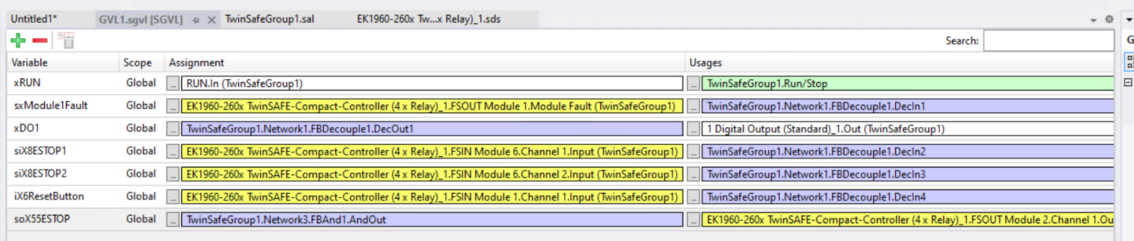
GVL1 – Role of each variable and links to it
This is the variable defined in this article.
| variable name | Description | Connections within TwinSAFE | Connection to actual equipment |
| xRUN | safety group execution signal | Run.In Connected | ― |
| sxModule1Fault | Fault signal for module 1. | FBDecouple1.DecIn1 input | FSOUT Module 1.Module Fault |
| xDO1 | Output signal (DO) | FBDecouple1.DecOut1 → actual output | ― |
| siX8ESTOP1 | Emergency stop button 1 contacts. | FBDecouple1.DecIn2 | FSIN Module 6.Channel 1 |
| siX8ESTOP2 | Auxiliary contacts for emergency stop button 2. | FBDecouple1.DecIn3 | FSIN Module 6.Channel 2 |
| iX6ResetButton | reset button | FBDecouple1.DecIn4 | FSIN Module 6.Channel 1 |
| soX55ESTOP | AND operation result (safety state) | FBAnd1.AndOut | FSOUT Module 2.Channel 1 |
safety group
The following section describes the programmes created within the safety group.
Overall summary (signal flow)
- The main contact (Mon1) and auxiliary contact (Mon2) of the emergency stop button are monitored by EDM.
- Time consistency OK → No Error
- If the reset button is pressed and both emergency stops are OK, AndOut = TRUE
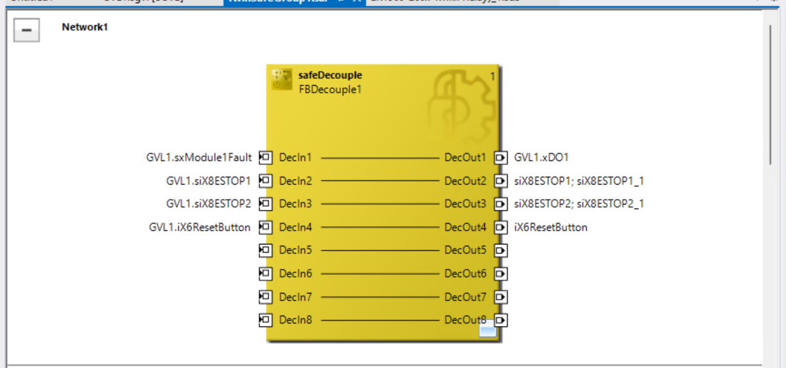
Network1 Decouple block
FBDecouple1 is a functional block for distributing physical inputs to several safety functions, which in turn distribute the variables defined in the GVL to the internal variables of the programme.
input(DecIn)
- DecIn1: Module fault detection (sxModule1Fault)
- DecIn2: Emergency stop button 1 (siX8ESTOP1)
- DecIn3: Emergency stop button 2 (siX8ESTOP2)
- DecIn4: Reset button (iX6ResetButton)
Output(DecOut)
- Distribute DecOut1 to DecOut4 to the respective processing blocks
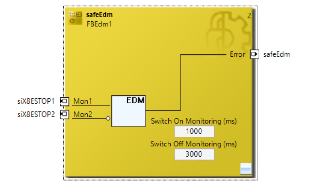
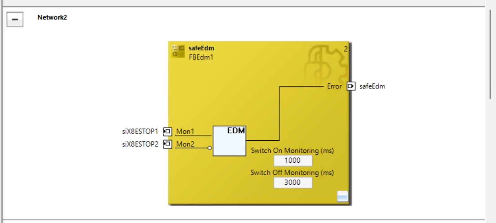
Network2 EDM monitoring block
FBEdm1 is a safety block that monitors the timing between Mon1 and Mon2 and uses this function to monitor the two emergency stop input points.
INPUT
- Mon1:siX8ESTOP1 → Main contacts of the emergency stop button
- Mon2:siX8ESTOP2 → Auxiliary contacts (e.g. safety relays) for emergency stop
Monitor Settings
- Switch On Monitoring:1000 ms (Mon1 goes from 0 to 1, then Mon2 goes to 0 or)
- Switch Off Monitoring:3000 ms (Mon1 goes from 1 to 0, then Mon2 goes to 1 or not)
出力
- Error:TRUE when an error occurs (FbError state inside the FB)
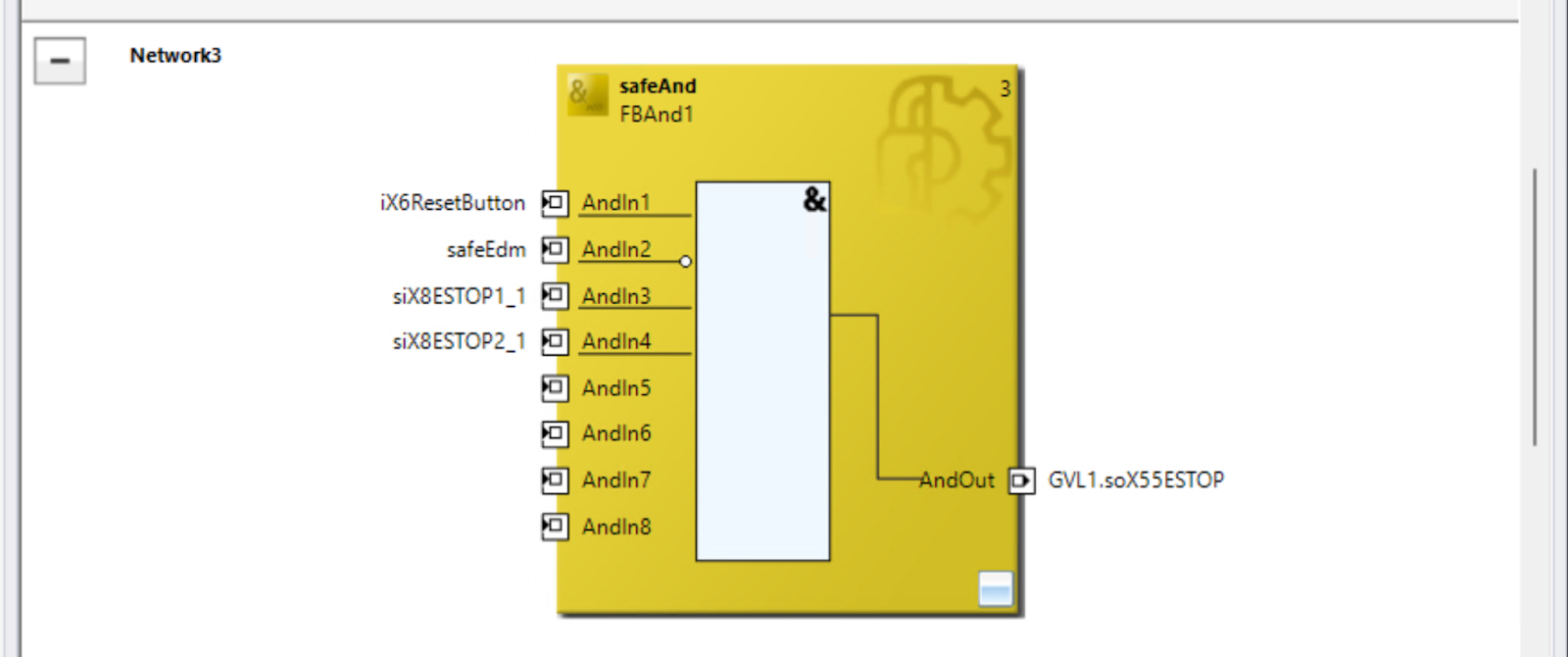
Network3 AND condition block
FBAnd1 is a block for a logical AND to check whether the safety conditions are met, and if the reset button is pressed and both emergency stops are OK, AndOut = TRUE.
INPUT
- AndIn1:Reset button (authorised after safety operation).
- AndIn2:EDM results (safeEdm, assuming no errors)
- AndIn3, 4:Both emergency stop contacts as expected (including auxiliary contacts)
出力
- AndOut → GVL1.soX55ESTOP:If this output is TRUE, the safety condition is considered to be clear.
Result
Indicates that the TwinSAFE EDM block is ‘in good working order’.
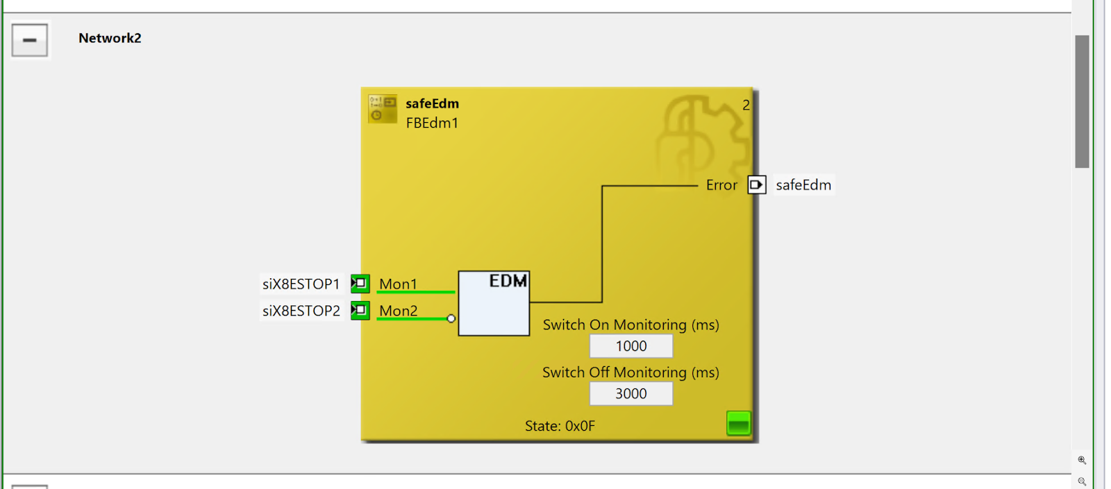
The operation of the actual machine can be checked in the demonstration video uploaded on YouTube.