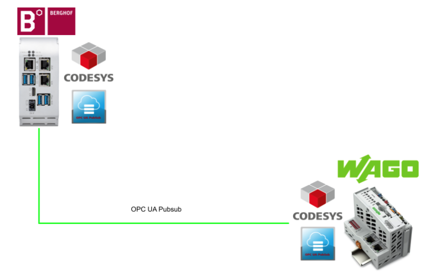
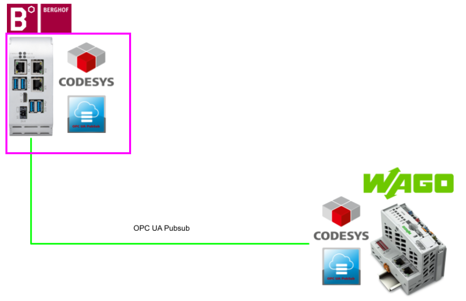
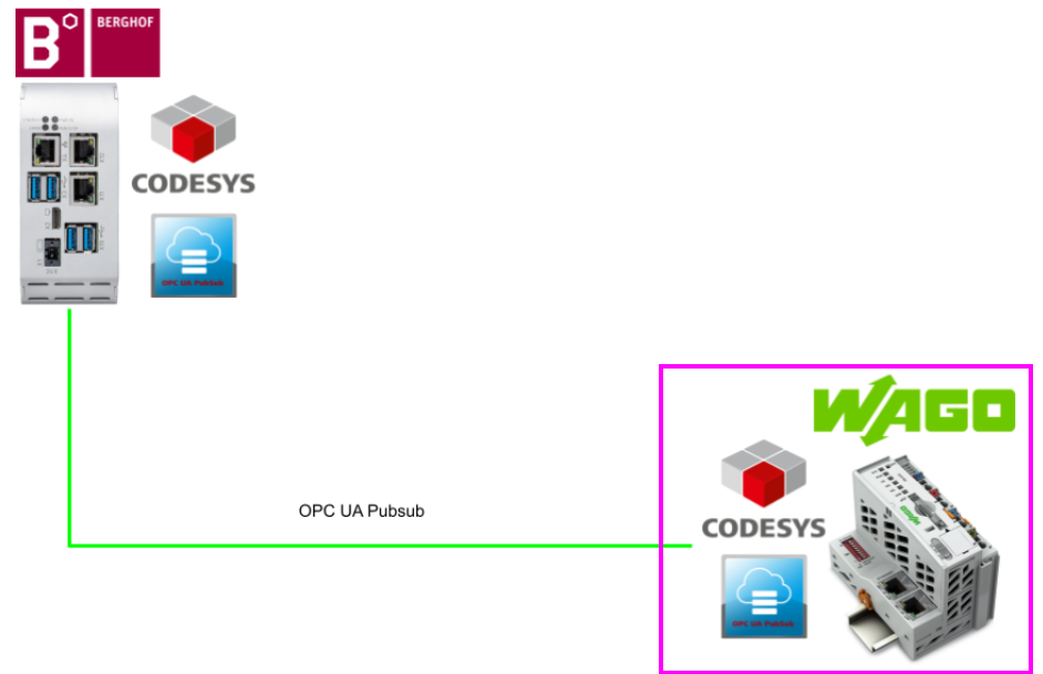
In this article, the Berghof MC-PI controller and WAGO’s PFC100 use OPC UA PubSub communication to exchange data.
Come on, let’s enjoy FA!。

Reference Link
Foreword
Thank you from the bottom of my heart for visiting my technical blog and YouTube channel.
We are currently running the “Takahashi Chris” radio show with Full-san (full@桜 八重 (@fulhause) / X) which I deliver every Wednesday night.
Sharing, not hoarding, technical knowledge
We publish technical information related to factory production technology and control systems for free, through blogs and videos.
With the belief that “knowledge should be accessible to everyone,” we share practical know-how and real-world troubleshooting cases from our own field experience.
The reason we keep it all free is simple: to help reduce the number of people who struggle because they simply didn’t know.
If you’ve ever thought:
- “Will this PLC and device combination actually work?”
- “I’m having trouble with EtherCAT communication—can someone test it?”
- “I want to try this remote I/O, but we don’t have the testing environment in-house…”
Feel free to reach out!If lending equipment or sharing your configuration is possible, we’re happy to verify it and share the results through articles and videos.
(We can keep company/product names anonymous if requested.)
How can you support us?
Currently, our activities are nearly all unpaid, but creating articles and videos takes time and a proper testing environment.If you’d like to support us in continuing and expanding this content, your kind help would mean a lot.
Membership (Support our radio show)
This support plan is designed to enhance radio with Mr Full.
https://note.com/fulhause/membership/join
Amazon Gift List (equipment & books for content production)
Lists equipment and books required for content creation.
https://www.amazon.co.jp/hz/wishlist/ls/H7W3RRD7C5QG?ref_=wl_share
Patreon (Support articles & video creation)
Your small monthly support will help to improve the environment for writing and verifying articles.
https://www.patreon.com/user?u=84249391
Paypal
A little help goes a long way.
https://paypal.me/soup01threes?country.x=JP&locale.x=ja_JP
Just trying to share things that could’ve helped someone—if only they’d known.
Your support helps make knowledge sharing more open and sustainable.
Thank you for being with us.
soup01threes*gmail.com
Technical knowledge shouldn’t be kept to ourselves.
CODESYS OPC UA PubSub
The Codesys OPC UA PubSub SL library enables message exchange via the Pub/Sub protocol defined by the OPC UA Foundation.
Communication via the OPC UA Pub/Sub protocol offers, in addition to client/server communication, the possibility of exchanging data between network subscribers in compliance with OPC UA Foundation regulations. It is important to note that the structure of the data (DataSet) can be freely defined and agreed upon in advance between the sender and receiver.
Data transfer is performed via UDP/IP with the help of the OPC UA PubSub SL library and according to the rules defined for UADP.
The publisher exposes its data to an unknown number of subscribers. In other words, the sender and recipient do not know each other. Therefore, the number of recipients does not affect the sender. The data is transferred in binary format according to OPC UA Foundation rules: the OPC UA PubSub SL library performs the conversion from the IEC data type to the corresponding OPC UA data type. This allows implementations to follow the following profile:
- Publisher: PubSub Publisher UADP fixed periodic settings
- Subscriber:PubSub Subscriber UADP regular fixed setting
Message length is limited to 1500 bytes (MTU) (Chunked NetworkMessages are not supported); unless Time Sensitive Network rules are still available, it cannot comply with hard real-time conditions. However, the OPC UA PubSub SL library implementation tries to keep jitter as low as possible.
Introducing
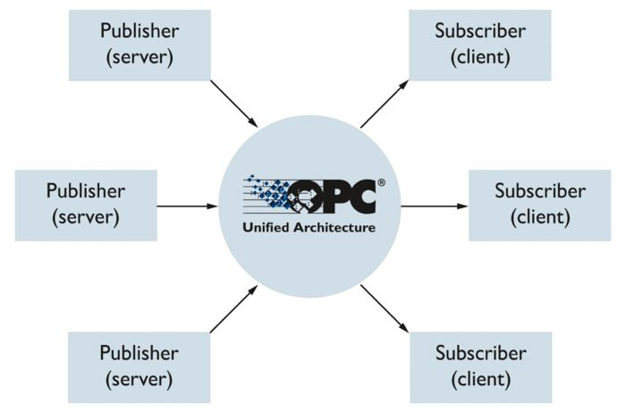
The Publish-Subscribe standard is the fourteenth part of the OPC UA specification. This standard was designed to extend the circumstances under which OPC UA can be employed to resolve and deepen automation; according to the OPC Foundation, PubSub enables OPC UA integration in two important ways.
In the case of the PubSub model of OPC UA, communication is connectionless and unconfirmed; PubSub stands for Publish and Subscribe, which allows the server to send data to the network (Publish) and all clients to receive that data (Subscribe). The server sends the data to the network (Publish) so that all clients can receive it (Subscribe).
In order to encrypt and decrypt data, both communication partners must have the same security credentials: either one publisher provides the data, which is received by any number of subscribers on the network, or a number of publishers send one subscriber to send the information. This makes OPC UA PubSub particularly suited for direct communication in the IoT and for fast cyclic processing at the field level.
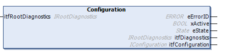
Configuration
This function block is used to represent the Pub/Sub configuration of the OPC UA application. If necessary, a RootDiagnostics instance is created and connected to itfRootDiagnostics. This provides diagnostic data for the OPC UA application through itfDiagnostics output.
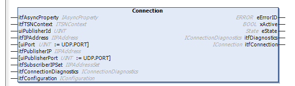
Connection
This function block represents a pub-sub connection. A pub-sub connection is a combination of protocol selection, protocol configuration, and address information.
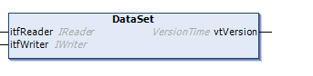
DataSet
Imagine that a DataSet is a list of variables; for publishing, the DataSet is encoded in a DataSetMessage.
In the CODESYS Forge area, there are two different DataSet design examples: a DataSet can be a simple list of variables or a complex structure with several variations of groups of variables.
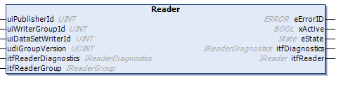
Reader
This function block is used to represent the dataset reader parameters. If necessary, create a ReaderDiagnostics instance and connect it to itfReaderDiagnostics. Provides diagnostic data for the dataset reader through itfDiagnostics output.
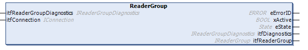
ReaderGroup
This function block is used to represent the configuration parameters of the reader group. If necessary, create a ReaderGroupDiagnostics instance and connect it to itfReaderGroupDiagnostics. Provide diagnostic data for the reader group through the itfDiagnostics output.
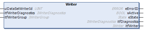
Writer
This function block is used to represent data set writer parameters.
If necessary, create a WriterDiagnostics instance and connect it to itfWriterDiagnostics. This will provide diagnostic data for the data set writer through itfDiagnostics output.
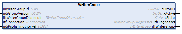
WriterGroup
This function block is used to represent WriterGroup configuration parameters.
If necessary, create a WriterGroupDiagnostics instance and connect it to itfWriterGroupDiagnostics. This will provide diagnostic data for the WriterGroup through itfDiagnostics output.
METHOD FINAL SetInitialValue : ERROR
SetInititalValue is a helper method for cases where static initialization does not work correctly in the context of a declaration due to compiler initialization sequences.
Implementation
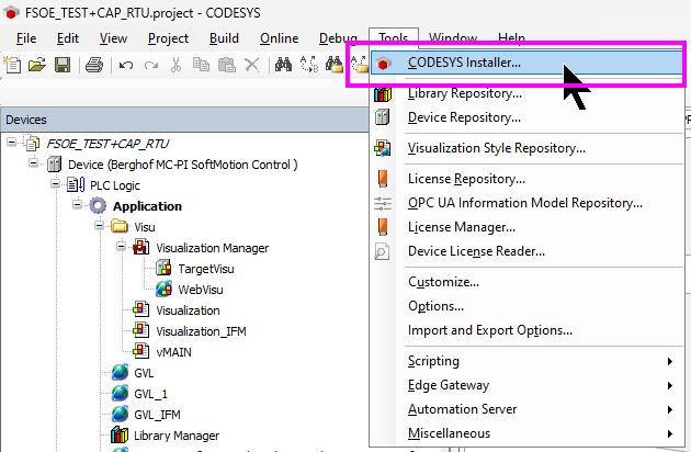
Install Library
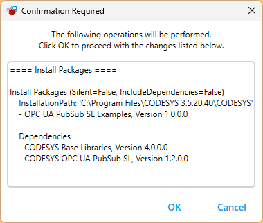
First click on Tools>CODESYS Installer to install the CODESYS OPC UA PubSub library.
The Codesys Installer screen will appear, search for OPC and select the Pubsub library>Install.
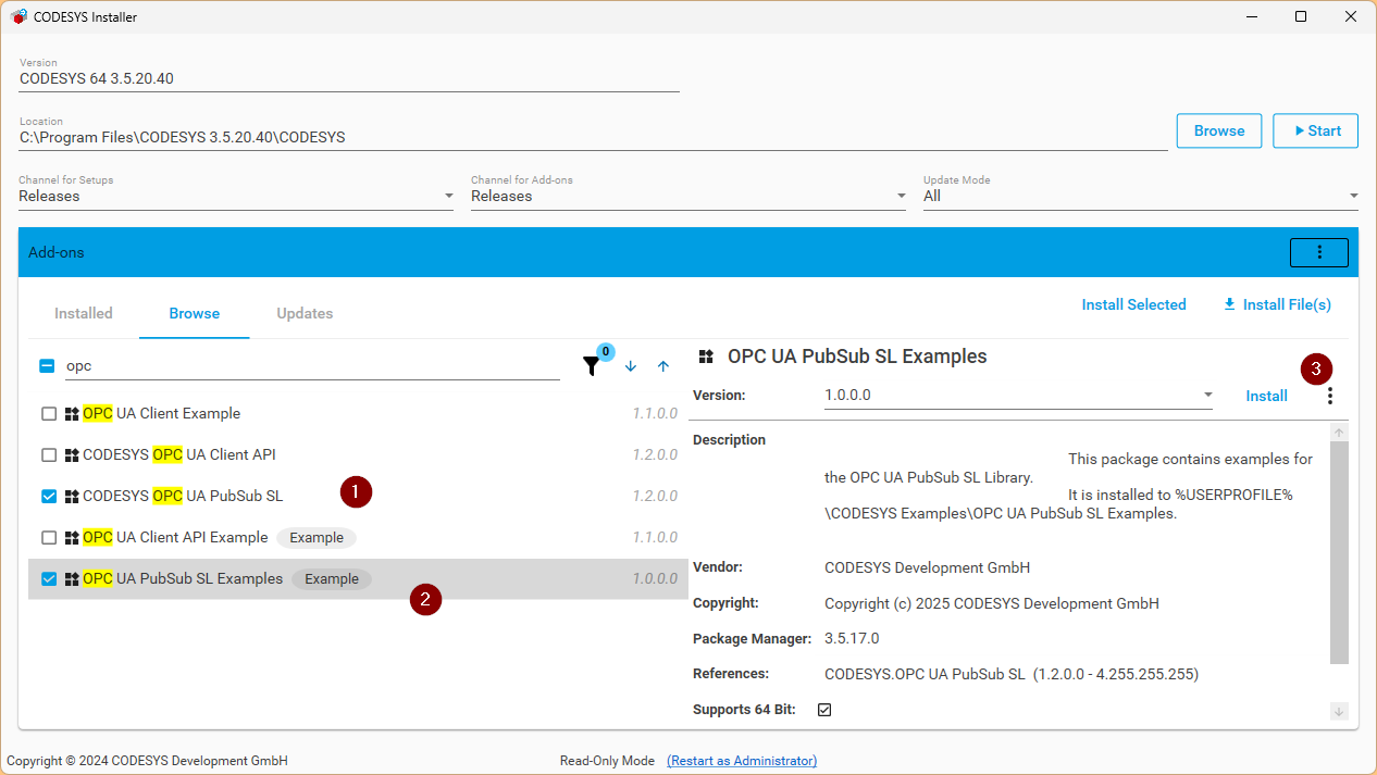
OK proceed.
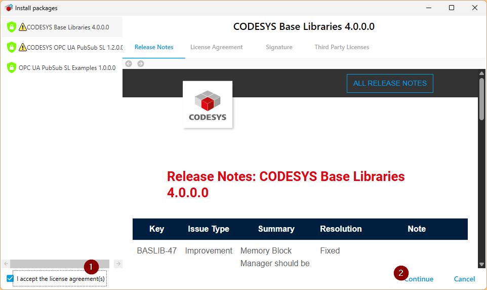
Accept the license and proceed with Continue.
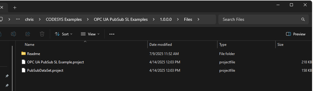
For your information, the sample project of OPC UA PubSub is stored in the following Directory.
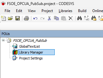
POUs Configuration
Since the two CPUs will be created in the same project for this article, open the POUs Tab and define common parameters, structures, etc.
Add Library
Click Library Manager to import the library.
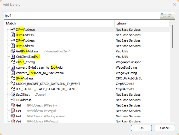
Search for Ipv4 and import the Net Base Services library.
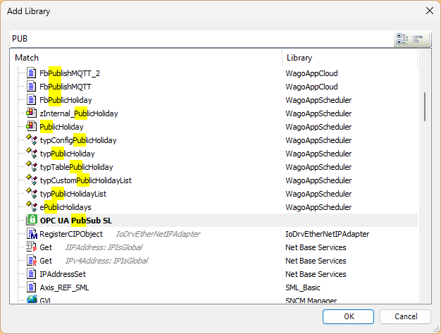
Next, let’s also install the OPC UA PubSub SL library.
DUT
Create structures in POUs.
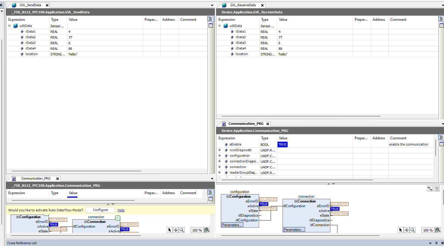
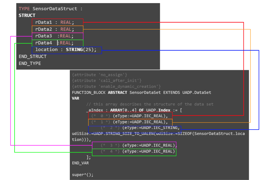
SensorDataStruct
Here is the data structure that the two Codesys controllers used in this article (Berghof’s MC-PI and WAO’s PFC100) exchange in OPC UA PubSub.
|
TYPE SensorDataStruct : |
|---|
GVL
GlobalIP
The GVLs here are WAGO PFC100 and Berghof IP addresses, multicast addresses, and OPC UA ports.
|
{attribute ‘qualified_only’} |
|---|

FB
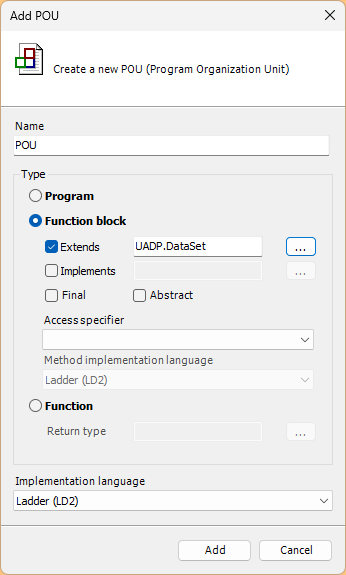
The next step is to create a Function Block.
SensorDataSet
Right click at the top of the project>Add Object>POU.
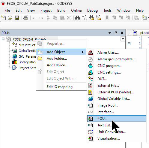
Set Type to Function block.
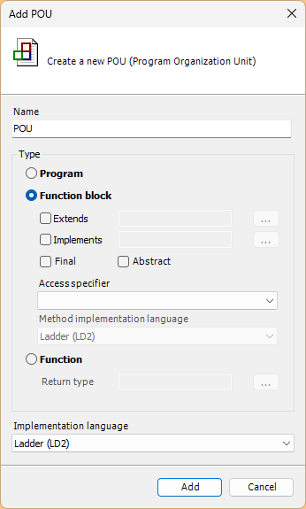
Put in the Option for Extends and click the … button next to it.
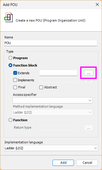
Search for the FB named DataSet.
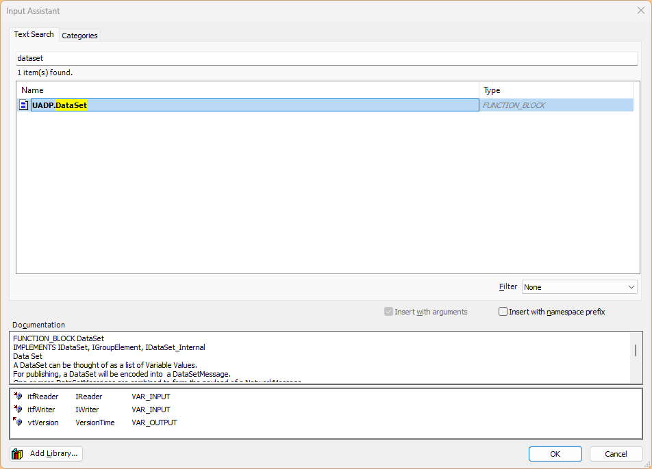
This is OK, click the Add button to add the FB.
VAR
In the VAR portion of the FB, Pub defines the data type of the variable you want to sub.
|
{attribute ‘no_assign’} super^(); |
|---|

Method -Init
Init Method is basically OK without modification.
|
{attribute ‘call_after_init’} |
|---|
Berghof Side
The first step is to build from the MC-PI controller on the Berghof side. In this article, the MC-PI controller is the Subscribers role.
GVL
Create GVL for OPC UA Subscribe.
GVL_ReceiveData
Variables are defined using the structure defined in POU earlier.
|
{attribute ‘qualified_only’} |
|---|
FB
rxSensorDataSet
The next step is to create a FB for OPC UA Subscribe.
The ioData is a parameter set up to allow variables to be passed from outside the FB.
|
{attribute ‘call_after_init’} |
|---|
Method-PrepareValues
PrepareValues is a program that transfers the address number of each Index variable.
|
// spread the received data over the application |
|---|
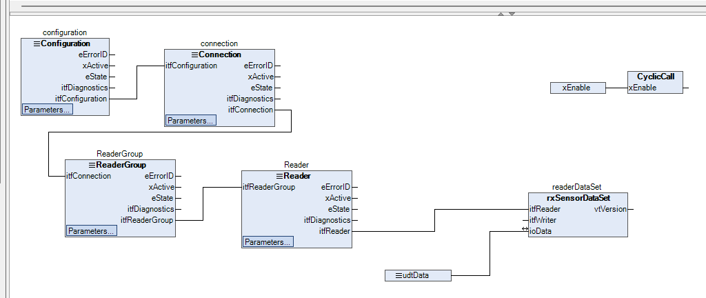
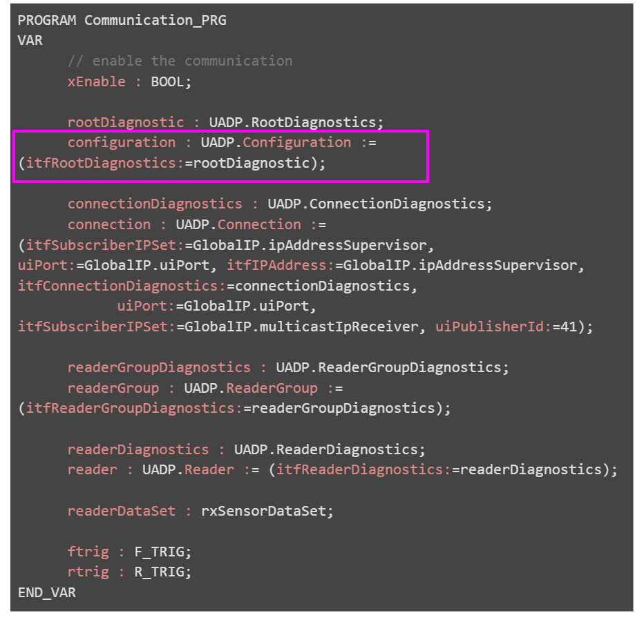
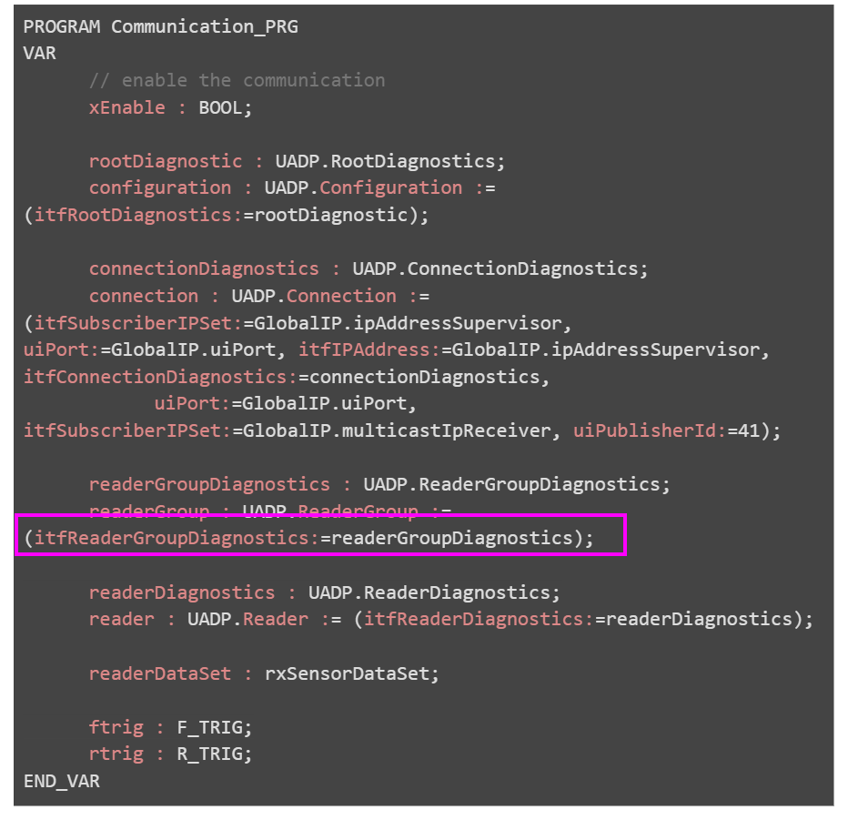
Program-Communication_PRG
Now let’s actually create a Pubsub communication program.
VAR
Define variables needed for the program in the VAR area.
|
PROGRAM Communication_PRG |
|---|
FLOW
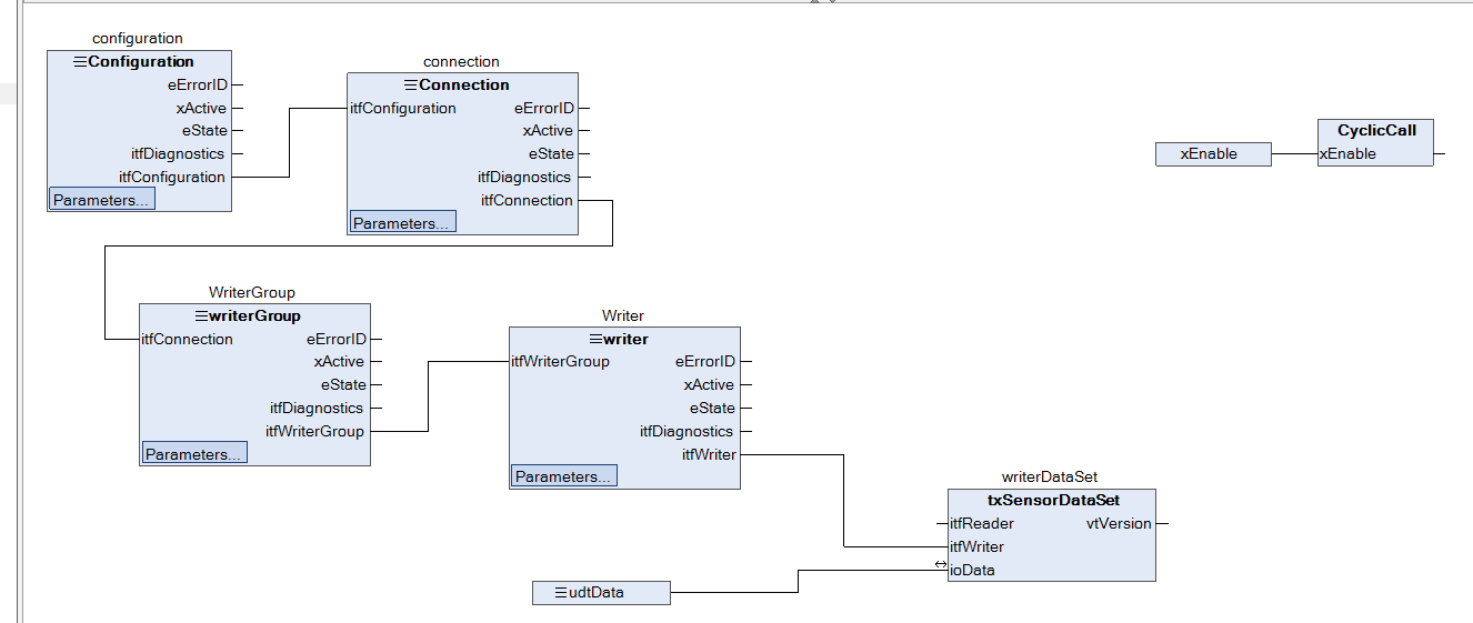
This is the overall FLOW of the communication program.
The flow is as follows: Setup→Connection→Reader and other settings→Start communication→TRUE the cycle execution method.
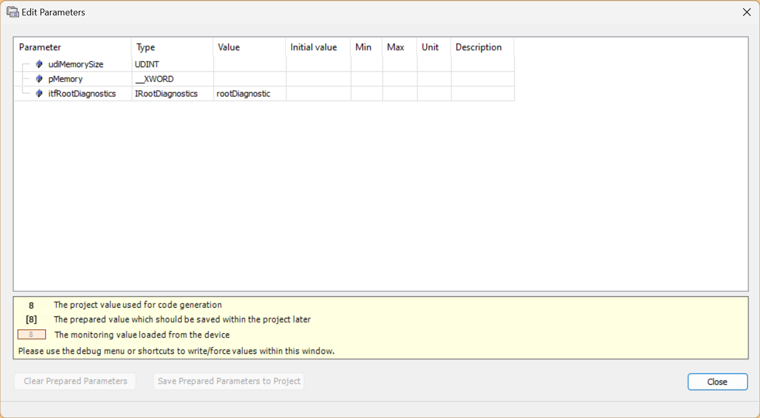
There is also a Configuration button on the FB for Configuration, etc.
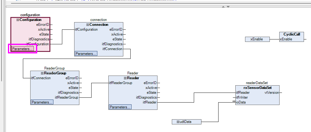
Click this button to assign the parameter settings for the corresponding FB.
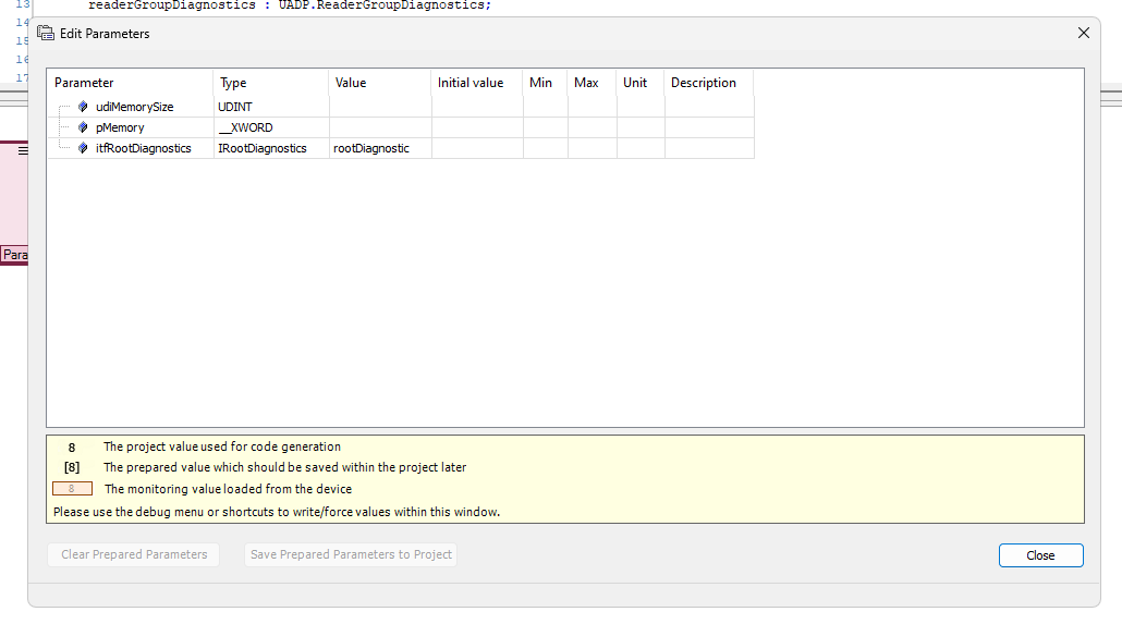
That is because the Configuration iftRootDiagnostics was initially assigned to rootDiagnostic.
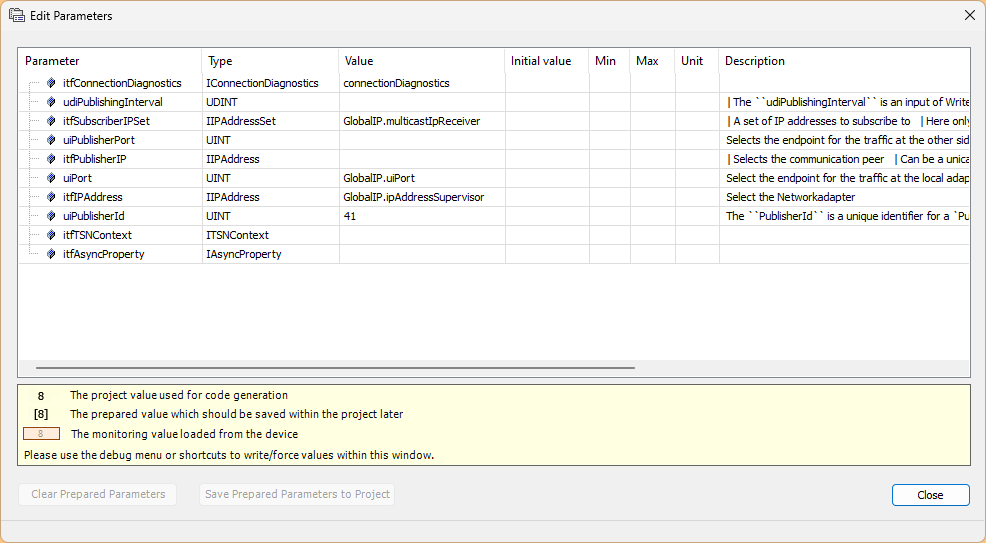
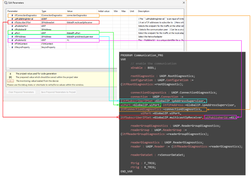
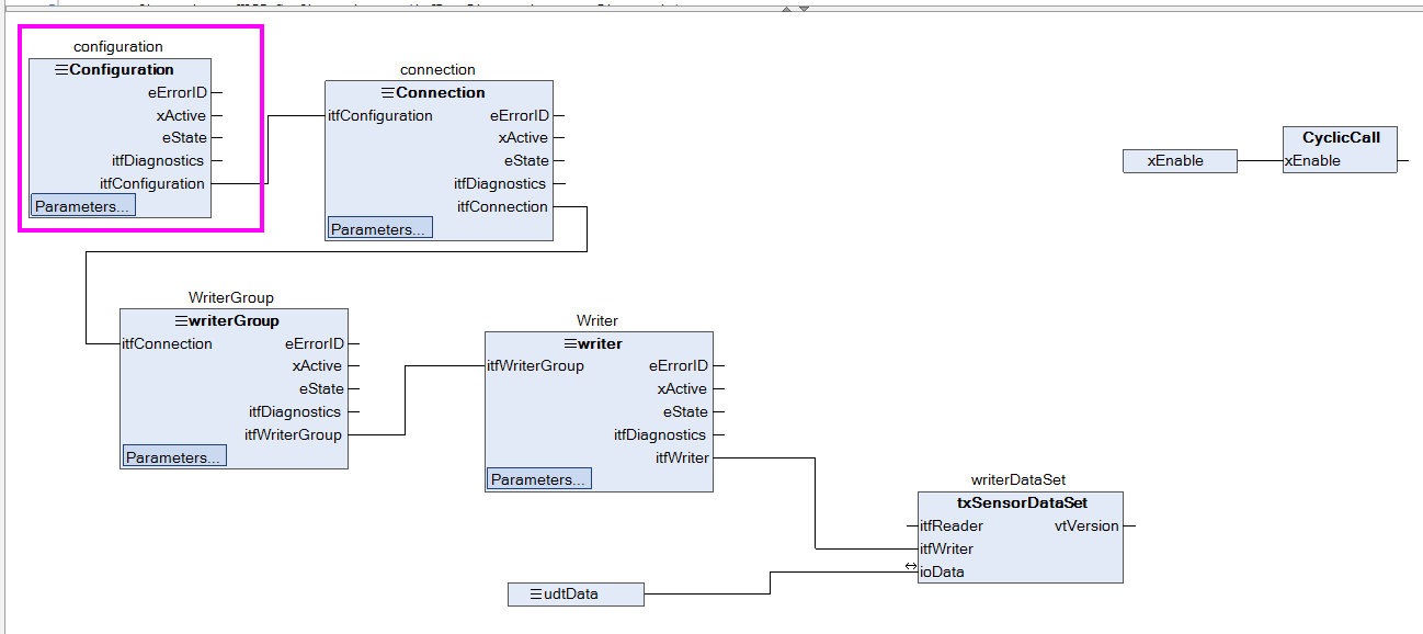
Configuration
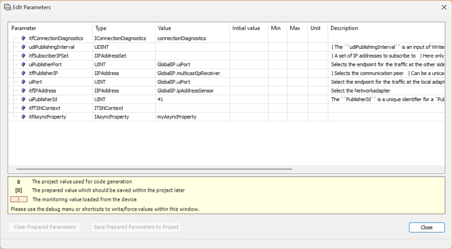
First, set the Configuration Block.
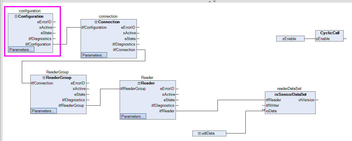
The variables are already assigned to diagnostic variables on the parameter screen.
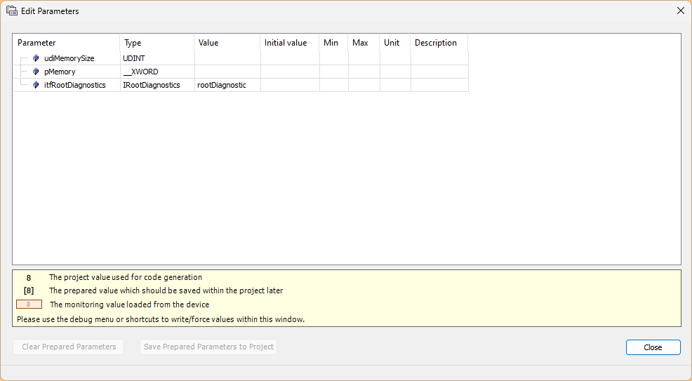
Then, let’s connect the output “itfConfiguration” of the Configuration FB Block with the input parameter “iffConfiguration in the next Connection block.
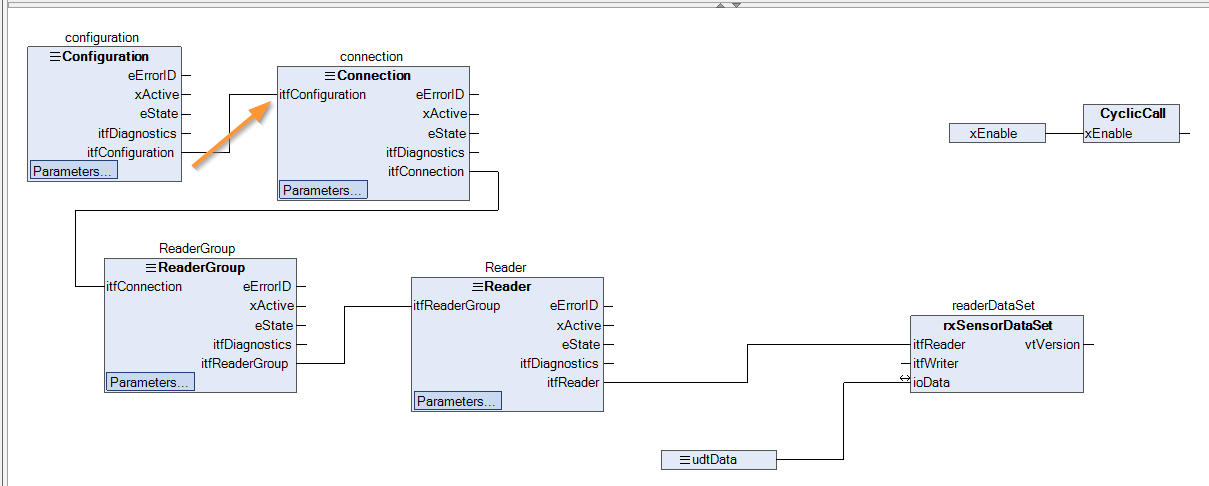
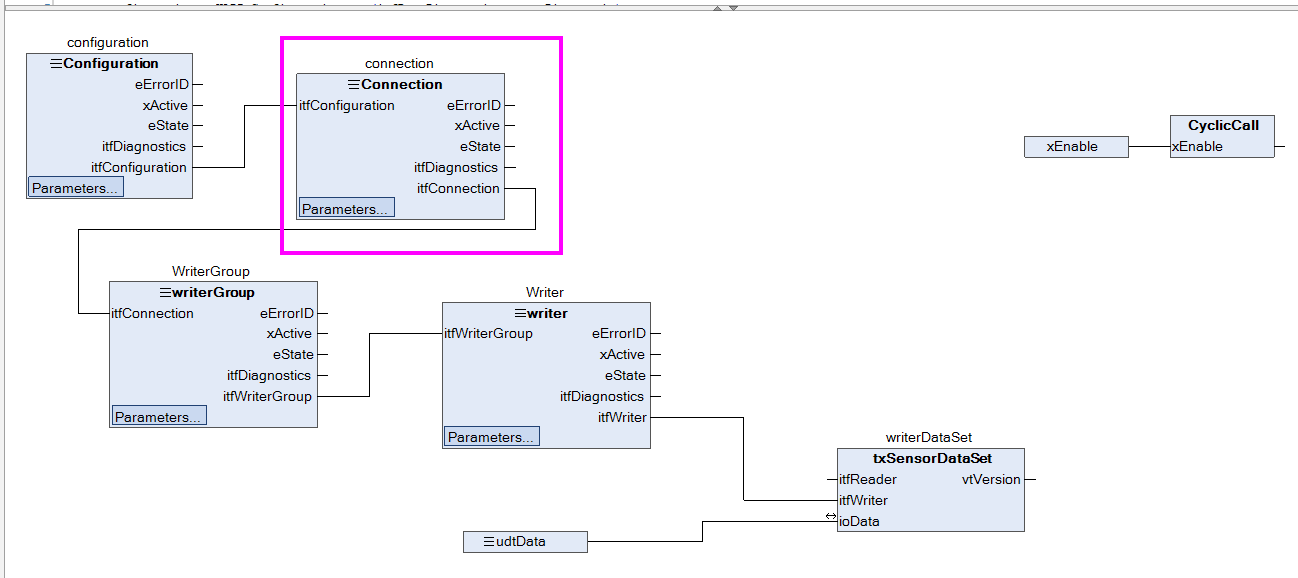
Connection
Next, create a Connection FB.
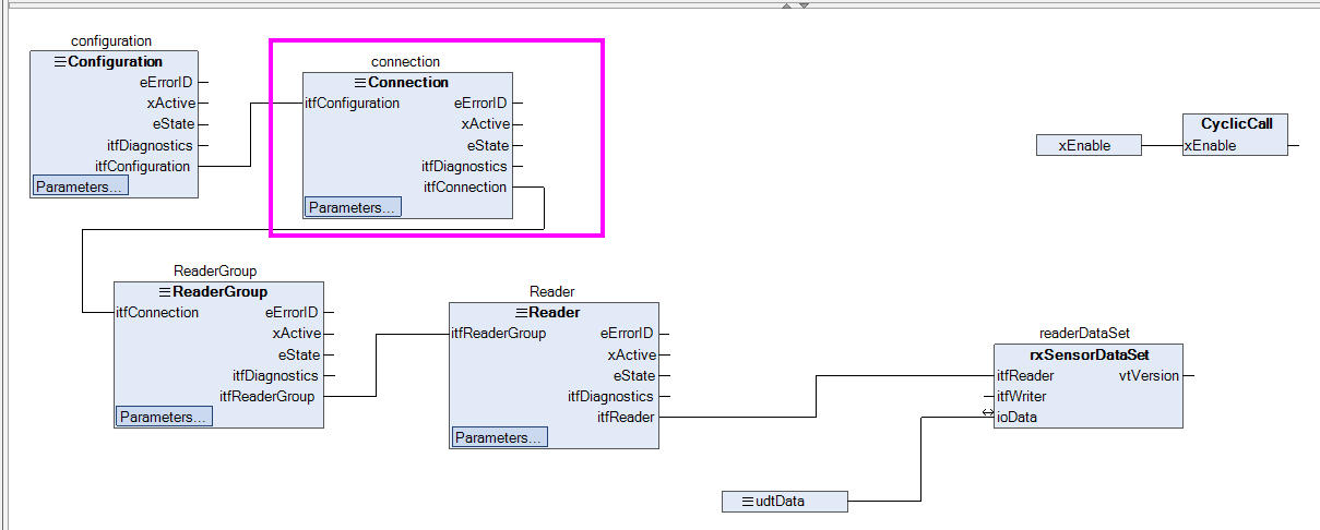
The required parameters are already in place in the Configuration Block.
When Instnace was defined as shown below, some parameters were already defined.
![]() Then, let’s connect the output “itfConnection” of the Connection FB Block with the input parameter “iffConnection” of the next ReaderGroup block. Let’s connect the output “itfConnection” of the Connection FB Block to the input parameter “iffConnection” of the next ReaderGroup block.
Then, let’s connect the output “itfConnection” of the Connection FB Block with the input parameter “iffConnection” of the next ReaderGroup block. Let’s connect the output “itfConnection” of the Connection FB Block to the input parameter “iffConnection” of the next ReaderGroup block.
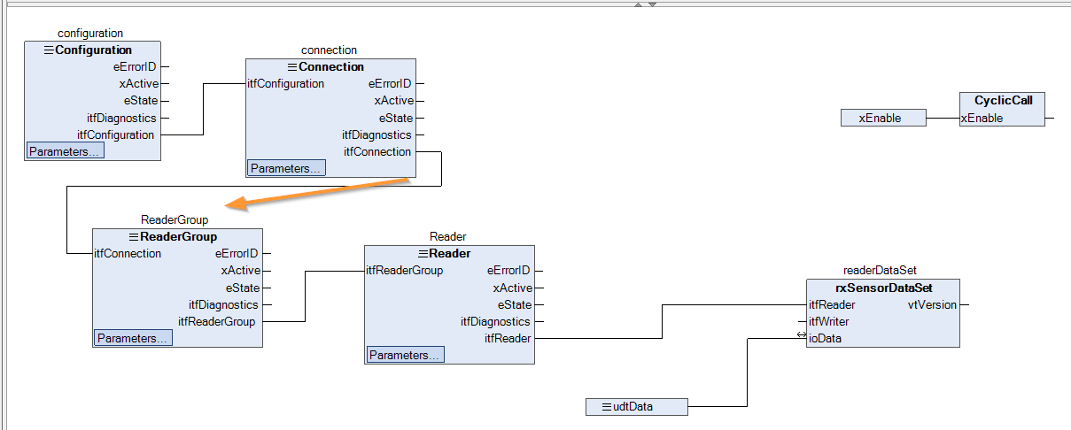
ReaderGroup
Now we will configure the ReaderGroup.
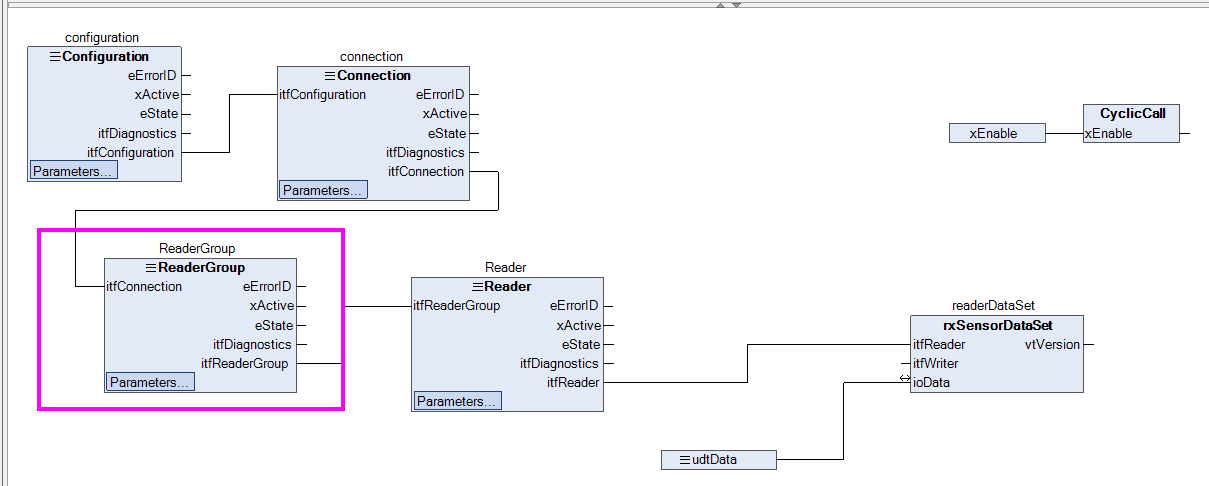
The parameters are already set as well.
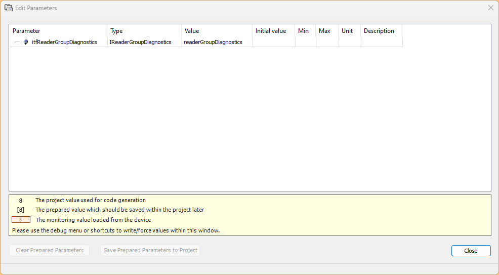
That is because ReaderGroup’s iftReaderGroupDiagnostics is initially rare and assigned to GroupDiagnostics.
Then, let’s connect the output “itfReader” of the ReaderGroup FB Block to the input parameter “iffReaderGroup” of the next Reader block Let’s connect the output “itfReader” of the FB Block to the input parameter “iffReaderGroup” of the next Reader block.
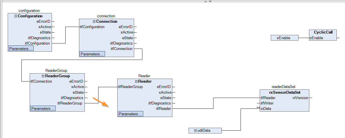
Reader
The Reader Block settings are also the same as other Communication Blocks.
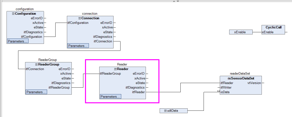
The parameters are already set as well.
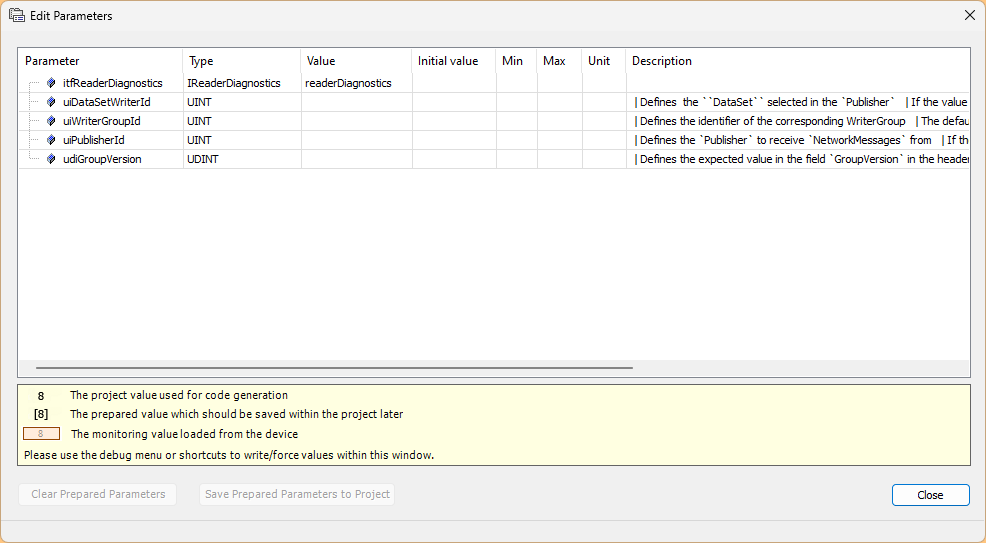
That is because the Reader’s iftReaderDiagnostics was initially assigned to readerDiagnostics, which is rare.
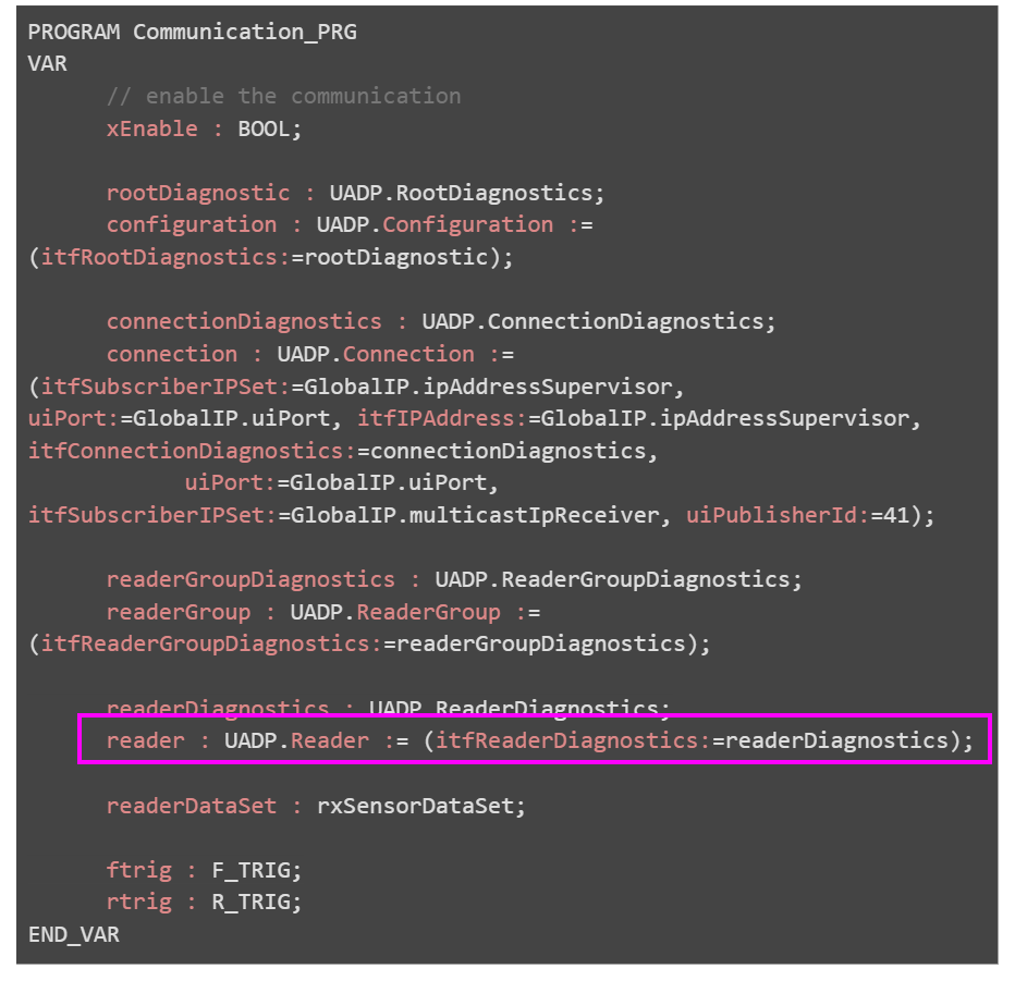
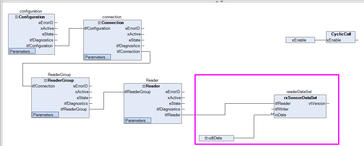
Then, let’s connect the output “itfReader” of the Reader FB Block to the input parameter “iftReader” of the FB rxSensorDataSet block we just created, which is extended to the next DataSet. Let’s connect the output “iffReader” of the FB Block to the input parameter “iftReader” of the FB rxSensorDataSet block we just created, which is Extended in the next DataSet.
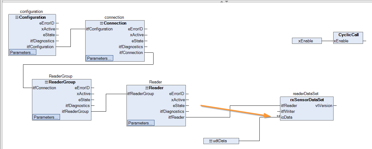
rxSensorDataSet
The rxSensorDataSet has no items to set when, and the ioData parameters are connected to the structure variables just defined in GVL.
CyclicCall
Input the Enable signal to the CyclicCall Method to enable cyclic execution of the program.
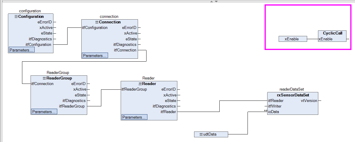
Method-CyclicCall
This is the CyclicCall program.
- When Enable detects a rising signal, it sets the Enable signal True for all Blocks.
- If Enable detects a falling signal, it will set the Enable signal to False for all Blocks.
|
ftrig(CLK:=xEnable); |
|---|
Download
Finally, please DOWNLOAD the project.
WAGO Side
The next step is to build the WAGO PFC100 side. In this article, PFC100 is the Publisher role.
GVL
Create GVL for OPC UA Publish.
GVL_SendData
Variables are defined using the structure defined in POU earlier.
|
{attribute ‘qualified_only’} |
|---|
FB
txSensorDataSet
The next step is to create a FB for OPC UA Publish.
ioData is a parameter set up to allow variables to be passed from outside the FB.
|
{attribute ‘call_after_init’} |
|---|
Method-PrepareValues
PrepareValues is a program that transfers the address number of each Index variable.
|
// spread the received data over the application |
|---|
Program-Communication_PRG
Now let’s actually create a Pubsub communication program.
VAR
Define variables needed for the program in the VAR area.
|
PROGRAM Communication_PRG
|
|---|
FLOW
This is the overall FLOW of the communication program.
The flow is as follows: Setup → Connection → Writer and other settings → Communication start → TRUE for the cycle execution method.
Configuration
First, set the Configuration Block.
The variables are already assigned to diagnostic variables on the parameter screen.
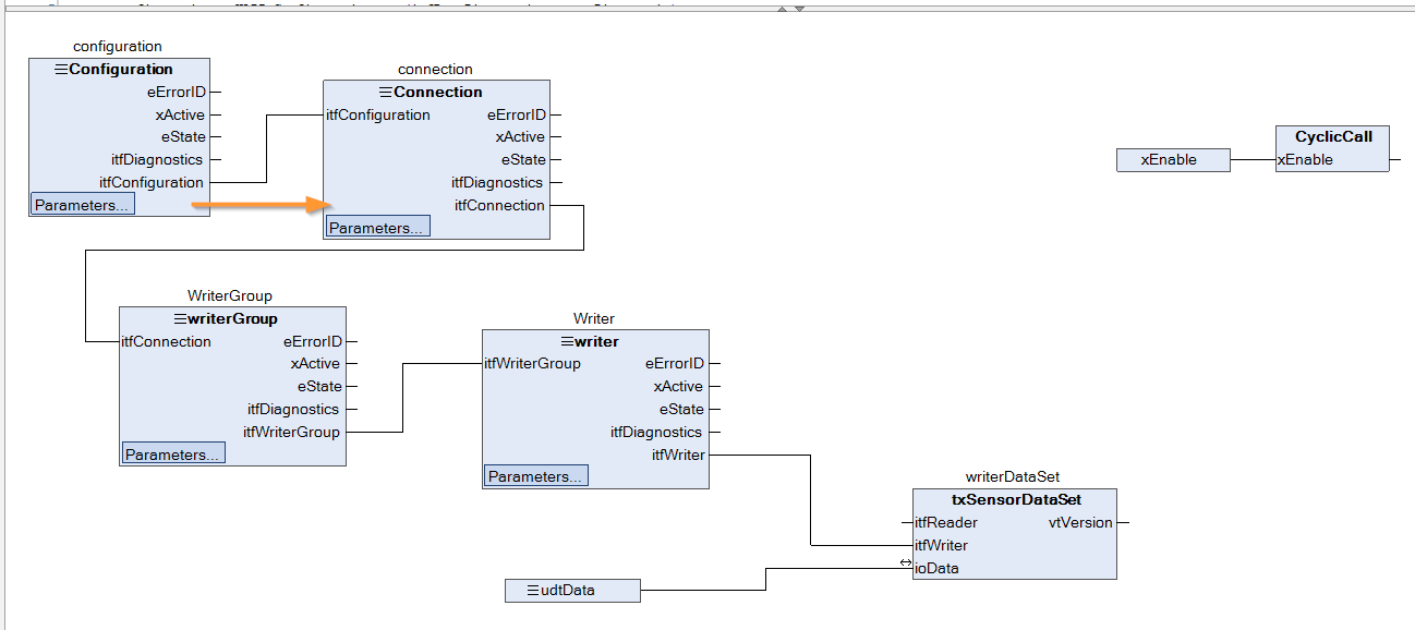
Then, let’s connect the output “itfConfiguration” of the Configuration FB Block with the input parameter “iffConfiguration in the next Connection block.
Connection
Next, create a Connection FB.
The required parameters are already in place in the Configuration Block.
Then connect the output “itfConnection” of the Connection FB Block to the input parameter “iffConnection” of the next WriterGroup block Let’s connect it to the input parameter “iffConnection” of the next WriterGroup block.
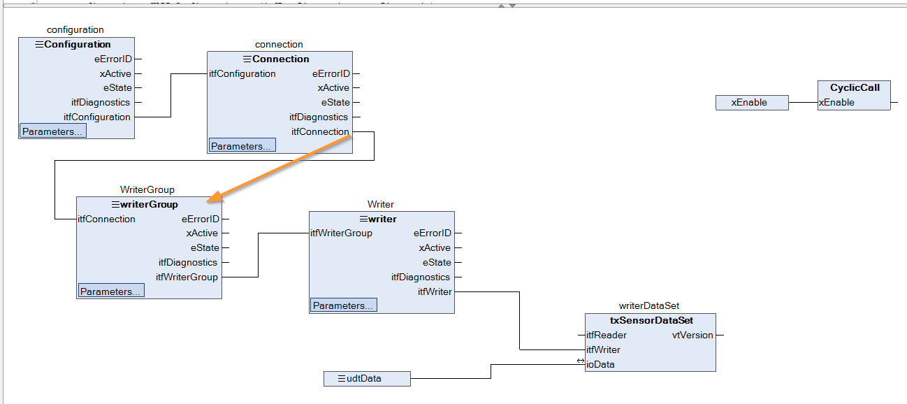
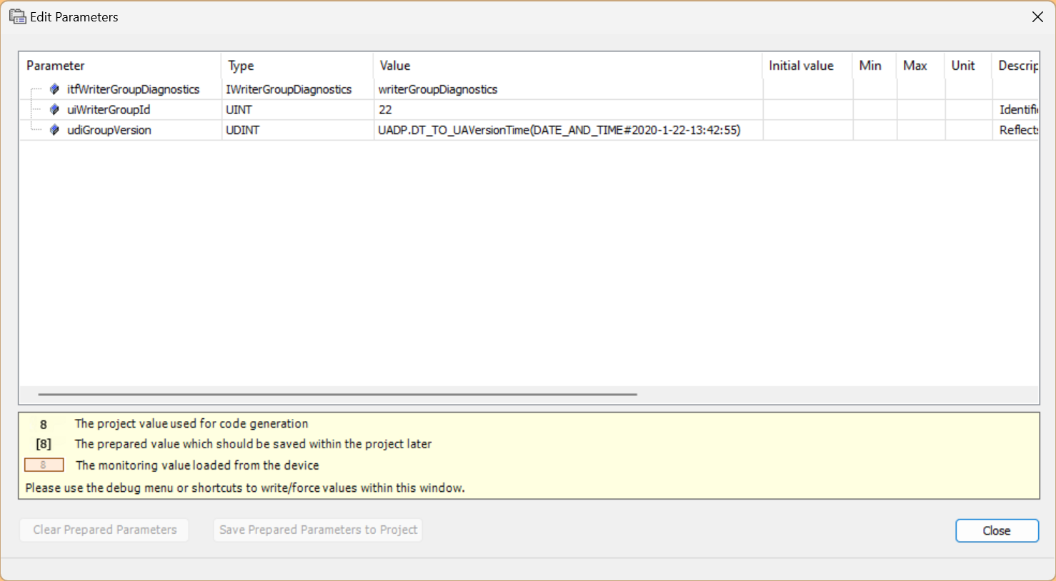
WriteGroup
This time it is WriteGroup.
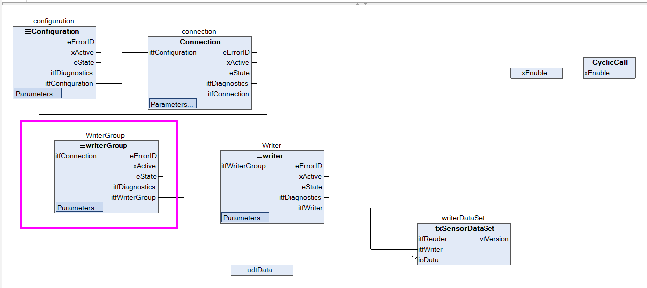
Parameters are already set as well.
Then, connect the output “itfReader” of the WriterGroup FB Block to the input parameter “iffWriterGroup” of the next Writerr block Let’s connect the output “itfReader” of the FB Block to the input parameter “iffWriterGroup” of the next Writerr block.
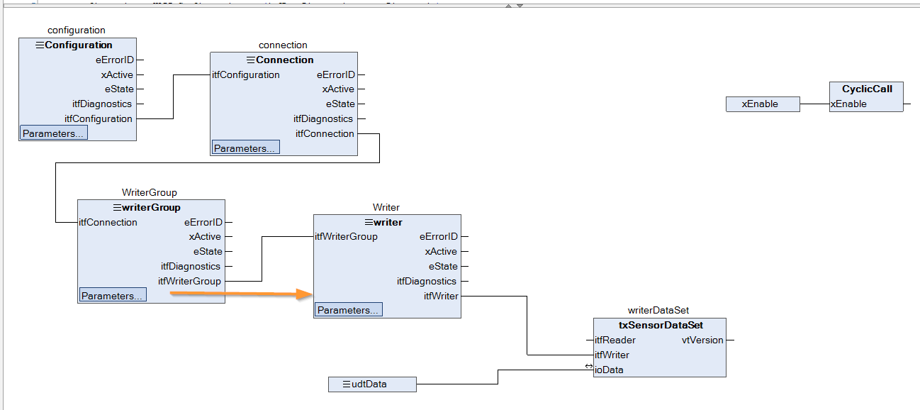
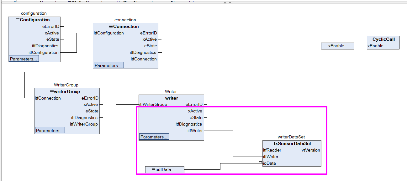
Writer
The Writer Block settings are also the same as for other Communication Blocks.
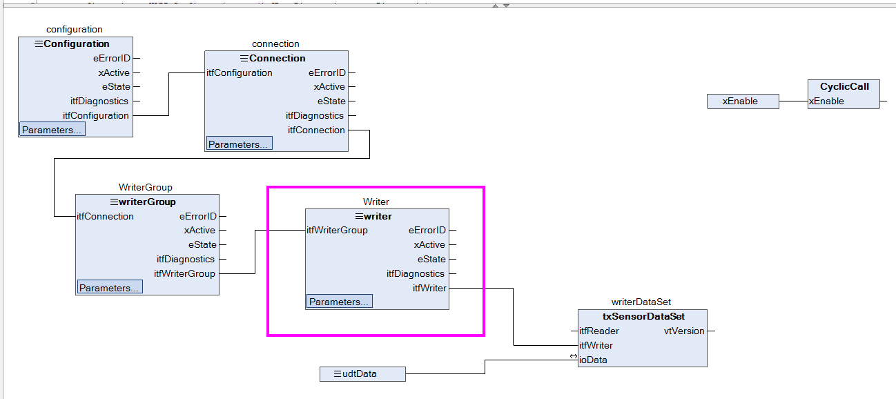
The parameters are already set as well.

Then, let’s connect the output “itfWriter” of the Writer FB Block to the input parameter “iftReader” of the FB txSensorDataSet block we just created, which is Extend to the next DataSet. Let’s connect it to the input parameter “iffReader” of the FB txSensorDataSet block that we just created.
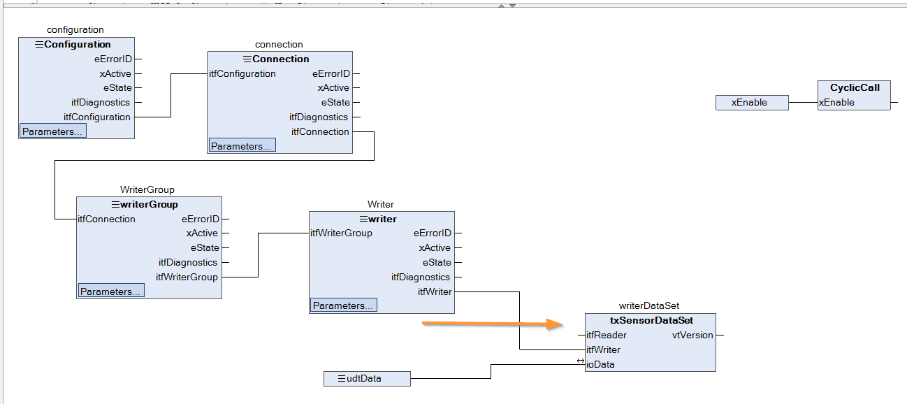
tsSensorDatSet
The txSensorDataSet has no items to set when, and the ioData parameters are connected to the structure variables just defined in GVL.
CyclicCall
Input the Enable signal to the CyclicCall Method to enable cyclic execution of the program.
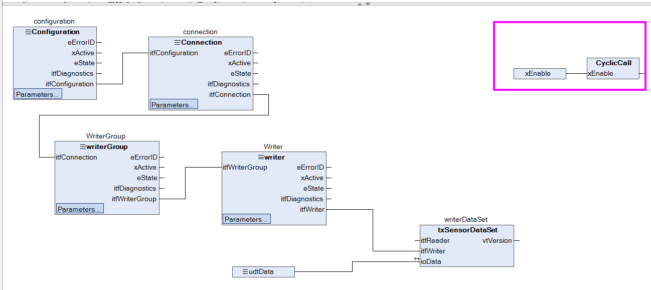
Method-CyclicCall
This is the CyclicCall program.
- When Enable detects a rising signal, it sets the Enable signal True for all Blocks.
- If Enable detects a falling signal, it will set the Enable signal to False for all Blocks.
Then program the data to be published to be variable.
|
METHOD CyclicCall : BOOL |
|---|
Download
Finally, please DOWNLOAD the project.
Result
Done!The Berghof MC-PI controller, shown below, and WAGO’s PFC100 controller can now communicate via OPC UA PubSub!