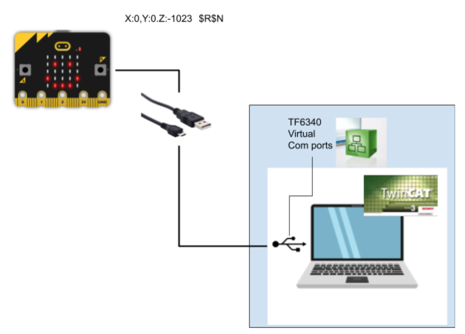
This post I will show you how to use Beckhoff TwinCAT3 TF6340 to serial Communicate with micro:bit. Why I chose Micro:bit – It is a very good device that has a 3-axis acceleration sensor, temperature sensor,etc. And the price is only 3000 yen.
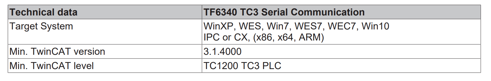
System Requirment
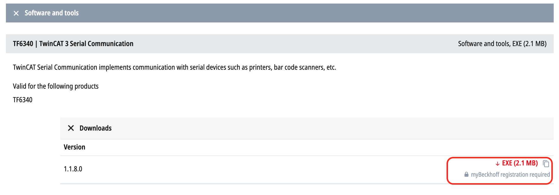
Install
Please access the following link to download the exe files.
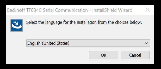
Choose English and OK.
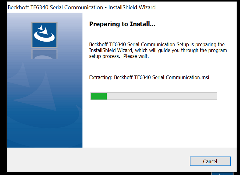
Please wait a second..
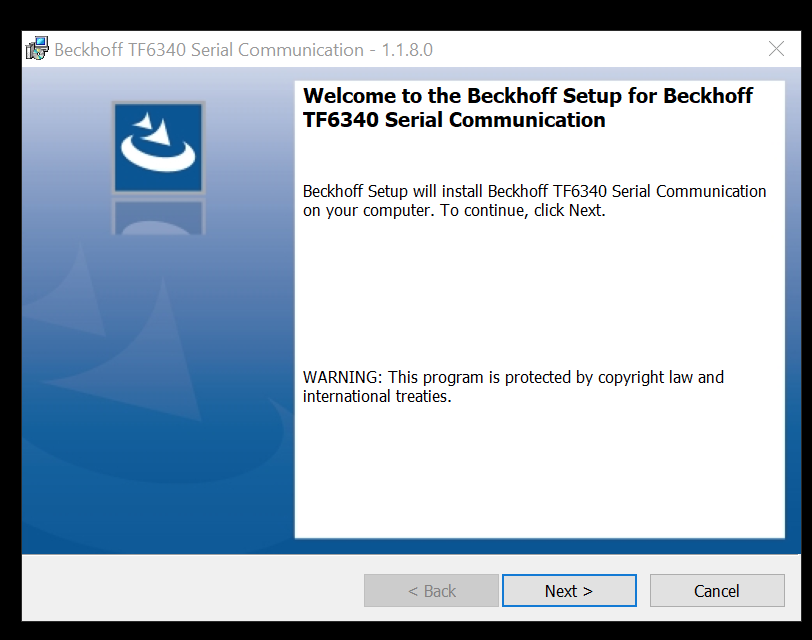
Click Next>.
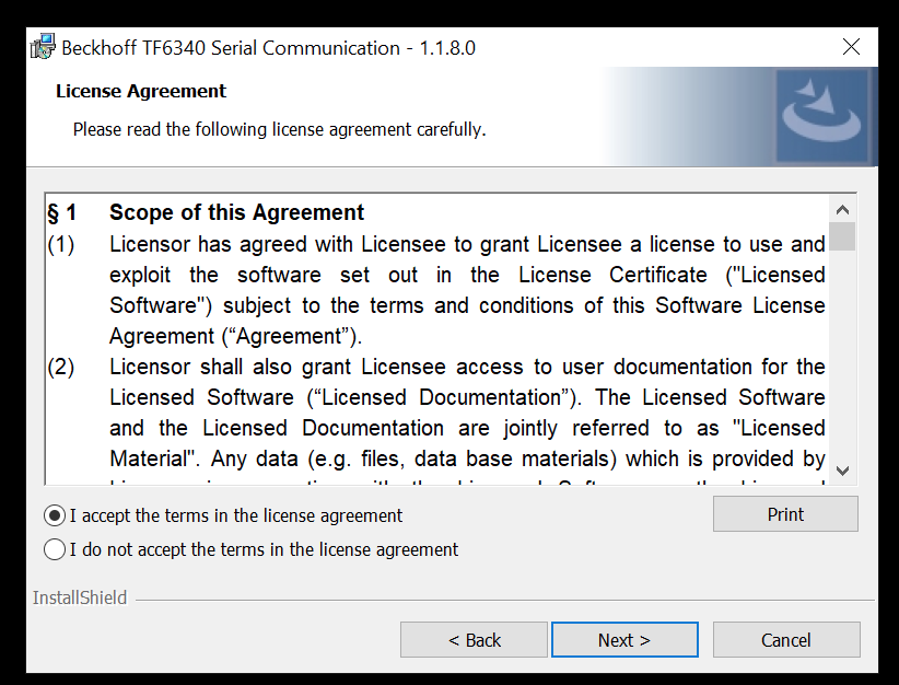
Accept the license and Press Next>.
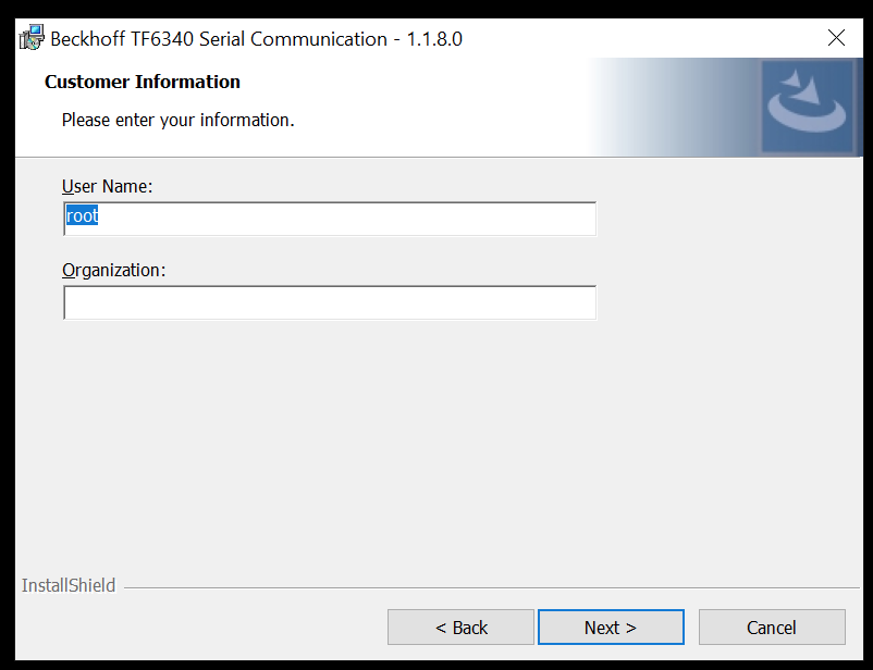
Enter the username and Organization, then press Next>.
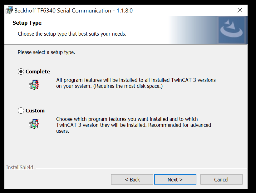
Choose Complete as your setup type and Press Next>.
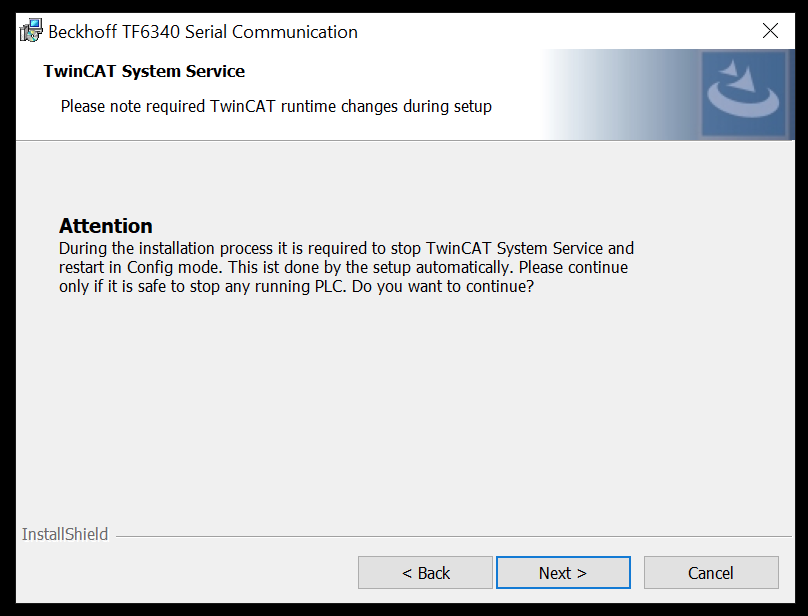
Next>.
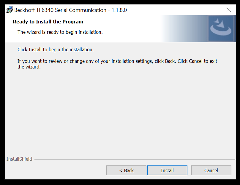
Install.
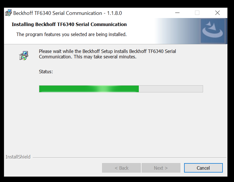
Please wait a second.
The installation is Finished.
Configuration
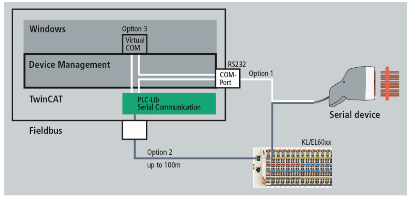
Reference to the Manual , there are 3 types of configuration of TF6340.
- Option 1: PC COM ports
- Connect COM Port directly to PLC.
- Option 2: Beckhoff terminals
- Connect the Devices to Beckhoff Field bus terminal (Max 100m)
- KL6xxx Bus Terminals
- EL60xx EtherCAT Terminals
- Connect the Devices to Beckhoff Field bus terminal (Max 100m)
- Option 3:Virtual COM port
- We will use this Option and make sure the usb that you connected , COM1..COMM255 is detected in your window system.
Support Hardware
まず最大の有効データ転送レート(bps)以下の要素に左右されます。
- PLC Cycle Time
- Total Bit that you need
- 1 Start bit
- N Data bits
- P parity bits
- m Stop bits
- Total:Start bit+n Data bit+ P Parity bits +m stop bit
I tried Option Serial PC interface and Virtual serial COM port and will explain these two options.
Serial PC Interface
The PC interface(COM1…COM255) is managed by the TwinCAT system.64 bytes buffer is used inside the Library – the max data exchange is 64 bytes in one time. And then the the system needs 3 cycles to exchange the data.
Bps=(LB*64/3)/T.
Virtual serial COM port
If we are using Virtual serial Com port(COM1..COM255), we do not need to configure anything in the TwinCAT system Manager.All the communication parameters are configured in the user program.
But this type of connection is not a Real-time communication.
The baud rate that you can set is from 150 to 128000.
Function Block
Sorry that I will only explain the Function Blocks that I am using in the example.
SerialLineControlADS
you need to cyclic call this block in the PLC and this block will manage the communication between PLC and Virtual serial interface.
If Connect is True, Runtime will refer to the SerialCfg setting and start to connect to the device.you need to change the status to false and true again while the SerialCfg setting is changed.All the stuff of port open,close is managed by Function block.
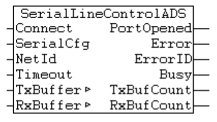
| VAR_INPUT | ||
| Connect | Bool | True=Open the Port False=Close the Port |
| SerialCfg | ComSerialConfig | Serial Port setting |
| NetId | T_AmsNetId | Keep empty while you access local. |
| Timeout | TIME | Default=5s |
| VAR_IN_OUT | ||
| TxBuffer | ComBuffer | Buffer of Data Transfer Function Block of SendByte,SendData, SendString will use this. |
| RxBuffer | ComBuffer | Buffer of Data ReceivedFunction Block ofReceiveByte, ReceiveData, ReceiveString will use this. |
| VAR_OUTPUT | ||
| PortOpened | BOOL | True=Port is opned |
| Error | BOOL | True=Error is occured |
| ErrorID | UDINT | |
| Busy | BOOL | True=ADS is communicating |
| TxBufCount | UDINT | data that TxBuffer is still not sent |
| RxBufCount | UDINT | data that RxBuffer is still not received |
ComSerialConfig
Basically the key setting is ComPort,Baudrate,Parity,DataBits.
| ComPort | UDINT | 1-255 |
| Baudrate | UDINT | |
| Parity | ComParity_t | |
| DataBits | INT | |
| DTR | ComDTRCtrl_t | |
| RTS | ComRTSCtrl_t | |
| CST | BOOL | |
| DSR | BOOL | |
| TraceLevel | BYTE | None=0;Error=1,Warning=2,Info=3,Verbose=4,Noise=5 |
| Reserved1 | BYTE | |
| Reserved2 | BYTE | |
| Reserved3 | BYTE |
ComBuffer
Do not directly modify the value of this variable.You only need is – define this variable and pass it as TxBuffer and RxBuffer parameters in SerialLIneControlAds.
| Buffer | ARRAY[0..300] OF BYTE | |
| RdIdx | INT | |
| WrIdx | INT | |
| Count | INT | |
| FreeByte | INT | |
| Error | INT | |
| blocked | BOOL |
ReceiveString
This is the Function Block to receive the data from serial communication as String format.
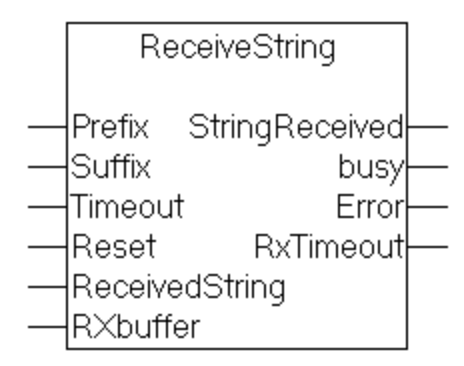
| VAR_INPUT | ||
| Prefix | STRING | if not empty, the starting characters must match with this. |
| Suffix | STRING | if not empty, the Ending characters must match with this.。 |
| Timeout | TIME | |
| Reset | BOOL | |
| VAR_IN_OUT | ||
| ReceivedString | STRING | Default=5s |
| RxBuffer | ComBuffer | Buffer of Data ReceivedFunction Block ofReceiveByte, ReceiveData, ReceiveString will use this. |
| VAR_OUTPUT | ||
| StringReceived | BOOL | True=String is Received |
| Busy | BOOL | True=Executing |
| Error | ComError_t | Error ID |
| RxTimeout | BOOL | True=Timeout |
micro:bit
Let’s take a serial communication test between your PC and micro:bit.
please click the follow links below:
https://makecode.microbit.org/
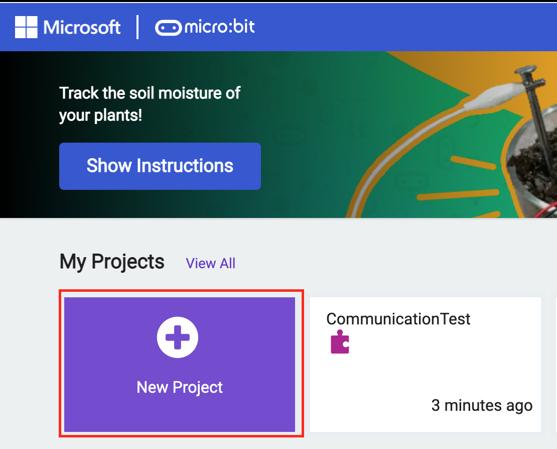
Go to My Projects>New Project.
We can program in the Web browser and IDE installation is not necessary.
you can use High languages just like javascript or Python but Blocks is used in this time.
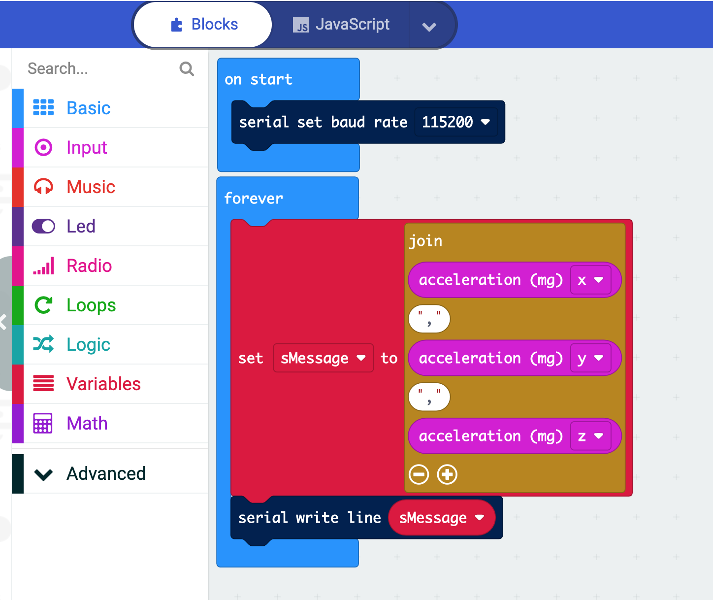
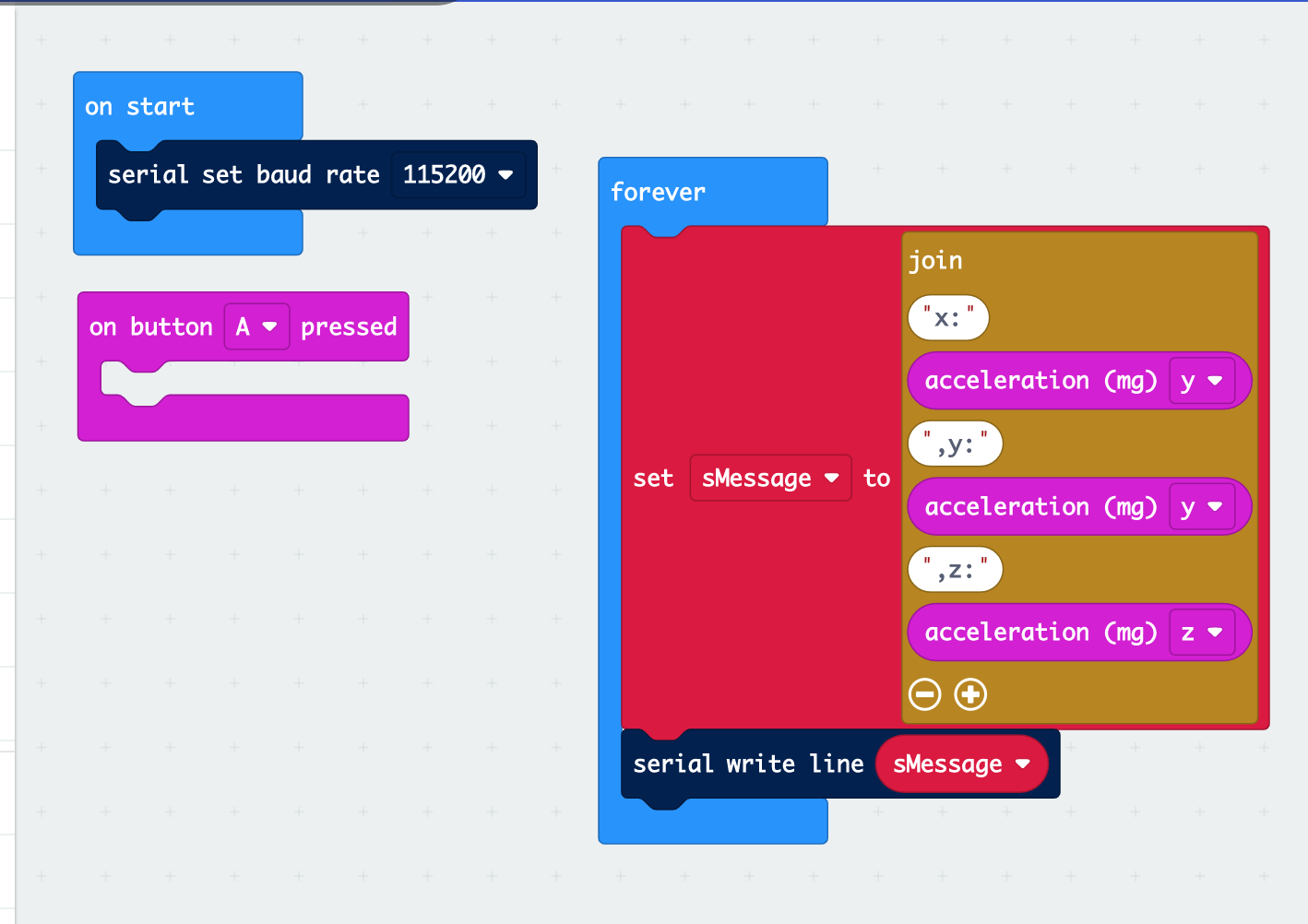
Here is the testing program.
It just creates a variables that called sMessage and join all the acceleration sensor values in String format, finally output to serial line.
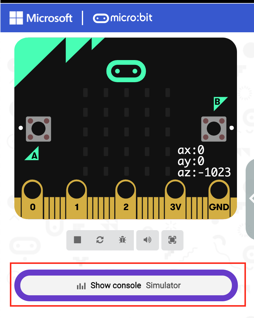
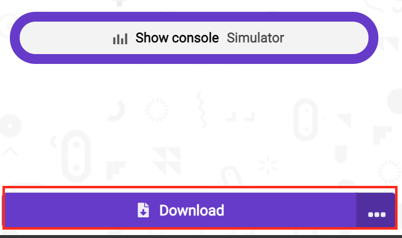
Let’s click the “Show Console Simulator” to view the output.
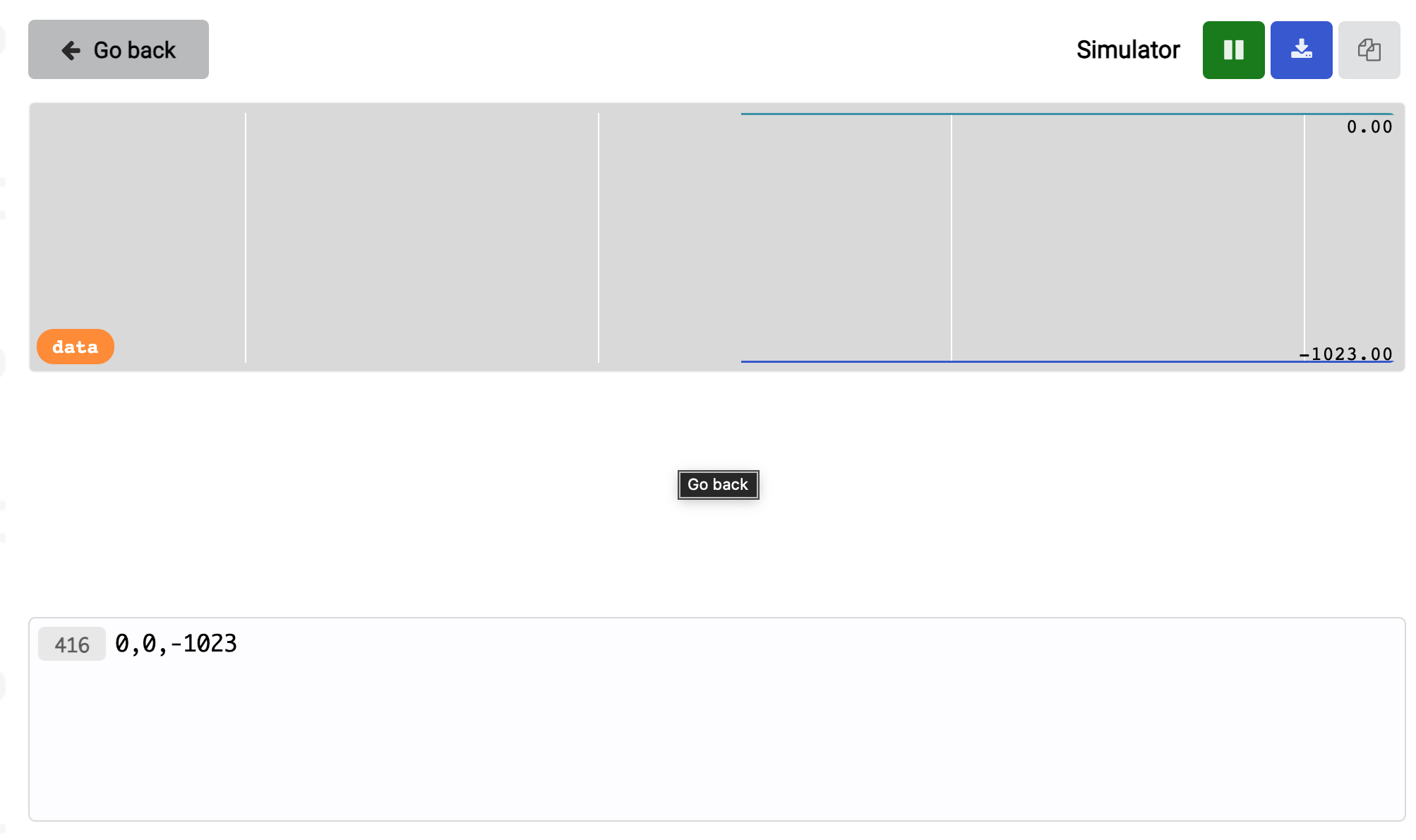
0,0,-1023 is shown.
416=currently output Count
0,0,-1023 are the acceleration sensor output value.
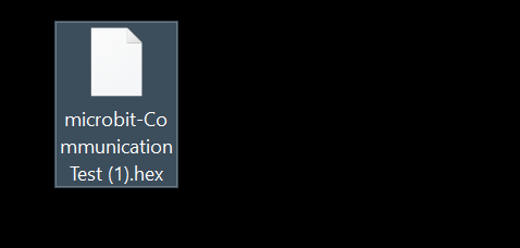
Click the Download button to Download your code.
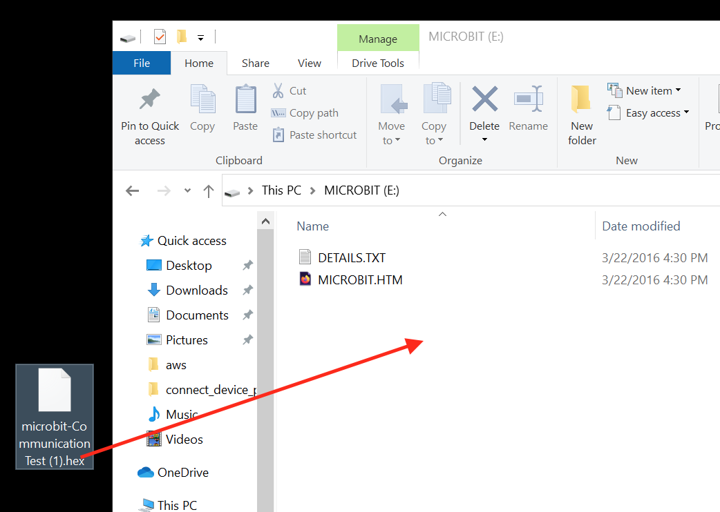
you can see the files with .hex on your PC.
Connect the micro:bit board with USB and drag the .hex files to micro:bit.
Test
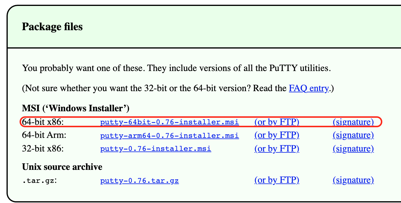
Putty is used in this testing and it is a very good tool.
Please download the link below.
https://www.chiark.greenend.org.uk/~sgtatham/putty/latest.html
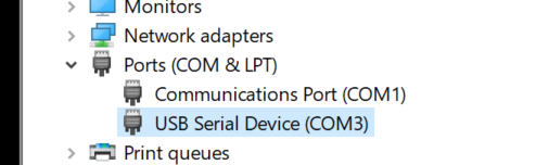
Start up the Device Manager.
confirm the COM port of micro:bit.
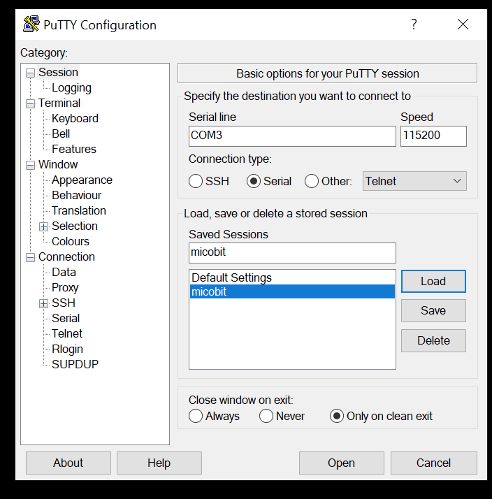
Start the Putty.
Connection Type:Serial
Serial line :COM3
Speed :115200
You can enter the name of sessions if you want to save the configurations,then press the “save” button.Next time you just need to choose the session you saved and then press the ”load” button.
Finally,Press the “Open” button to open the terminal.
If you can see the data that comes from Micro:bit, the communication is successful.
Example
Here is the Configurations.
Mirco:bit Side
Same as below.
Program
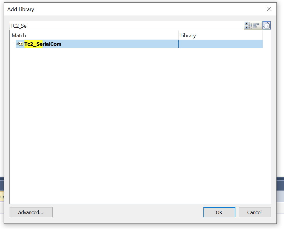
References>Add library.
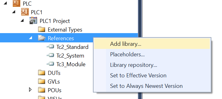
Search TC2_SerialCom and add it into your project.
VAR
| VAR RxBuffer :ComBuffer; TxBuffer :ComBuffer; SerialLineControlADS :SerialLineControlADS; bConnect :BOOL; stSerialCfg :ComSerialConfig; sNetId :T_AmsNetId; bAdsError :BOOL; bReset :BOOL; AdsErrorID :UDINT; ReceiveString :ReceiveString; data :STRING; nReceiveCounter :UDINT; END_VAR |
PROGRAM
you can refer to the setting in putty to match the serial communication setting in the user program.
| //Config stSerialCfg.Baudrate:=115200; stSerialCfg.ComPort:=3; stSerialCfg.DataBits:=8; stSerialCfg.StopBits:=1; stSerialCfg.Parity:=PARITY_NONE; //Reset IF bReset THEN bAdsError:=FALSE; nReceiveCounter:=0; END_IF //Open command line SerialLineControlADS( Connect:=bConnect ,SerialCfg:=stSerialCfg ,NetId:=sNetId ,Timeout:= ,TxBuffer:=TxBuffer ,RxBuffer:=RxBuffer ); //Error IF SerialLineControlADS.Error THEN bAdsError:=TRUE; AdsErrorID:=SerialLineControlADS.ErrorID; END_IF //Receive data ReceiveString( Prefix:=’x:’ ,Suffix:=’$R$N’ ,Timeout:= ,Reset:= ,ReceivedString:=data ,RXbuffer:=RxBuffer ); //Total Counter IF ReceiveString.StringReceived THEN nReceiveCounter:=nReceiveCounter+1; END_IF |
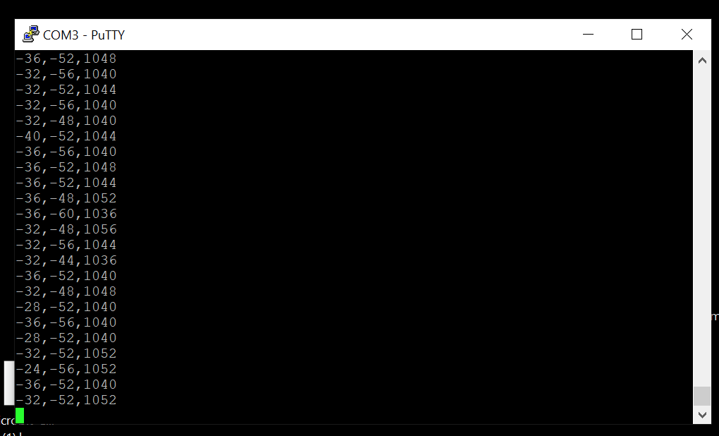
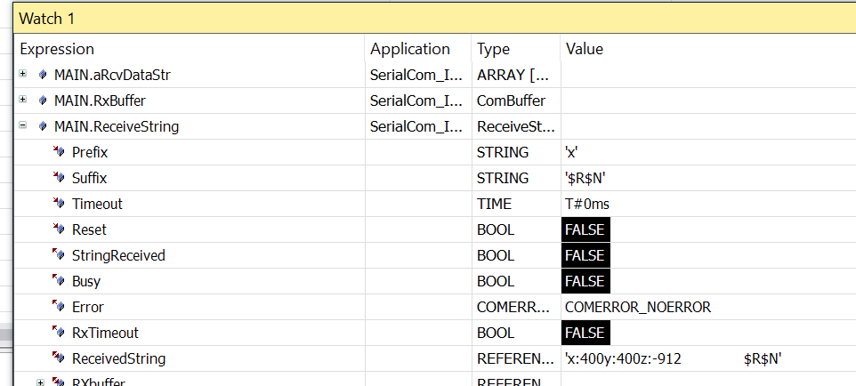
Result
You can see the data that sent from Micro:bit
Sample Code link:
https://github.com/soup01Threes/TwinCAT3/blob/main/TwinCAT%20Project_TF6340_connectwithMicobit.zip
Twitter:@3threes2
EMail:soup01threes*gmail.com (*to@)