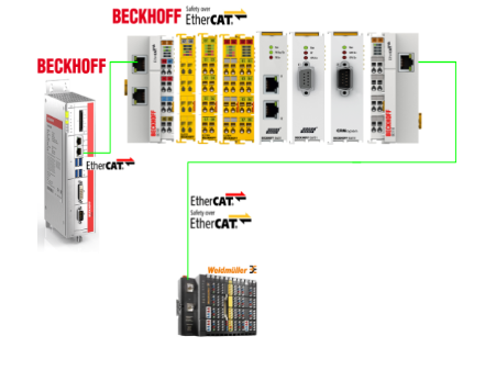
In this article, the EtherCAT Master is set up from a Beckhoff C6920 and the EL6910 is connected to a weidmueller UR20-FBC-EC-ECO (EtherCAT Coupler) UR20-4DI-4DO-PN-FSOE-V2 (FSOE SubDevices module) are connected to explain the EtherCAT and FSoE communication set-up.
Let’s start!
Reference Link
Reference Video
Beckhoff.Let’s connect Weidmueller’s UR20-FBC-EC-ECO with FSOE EL6910
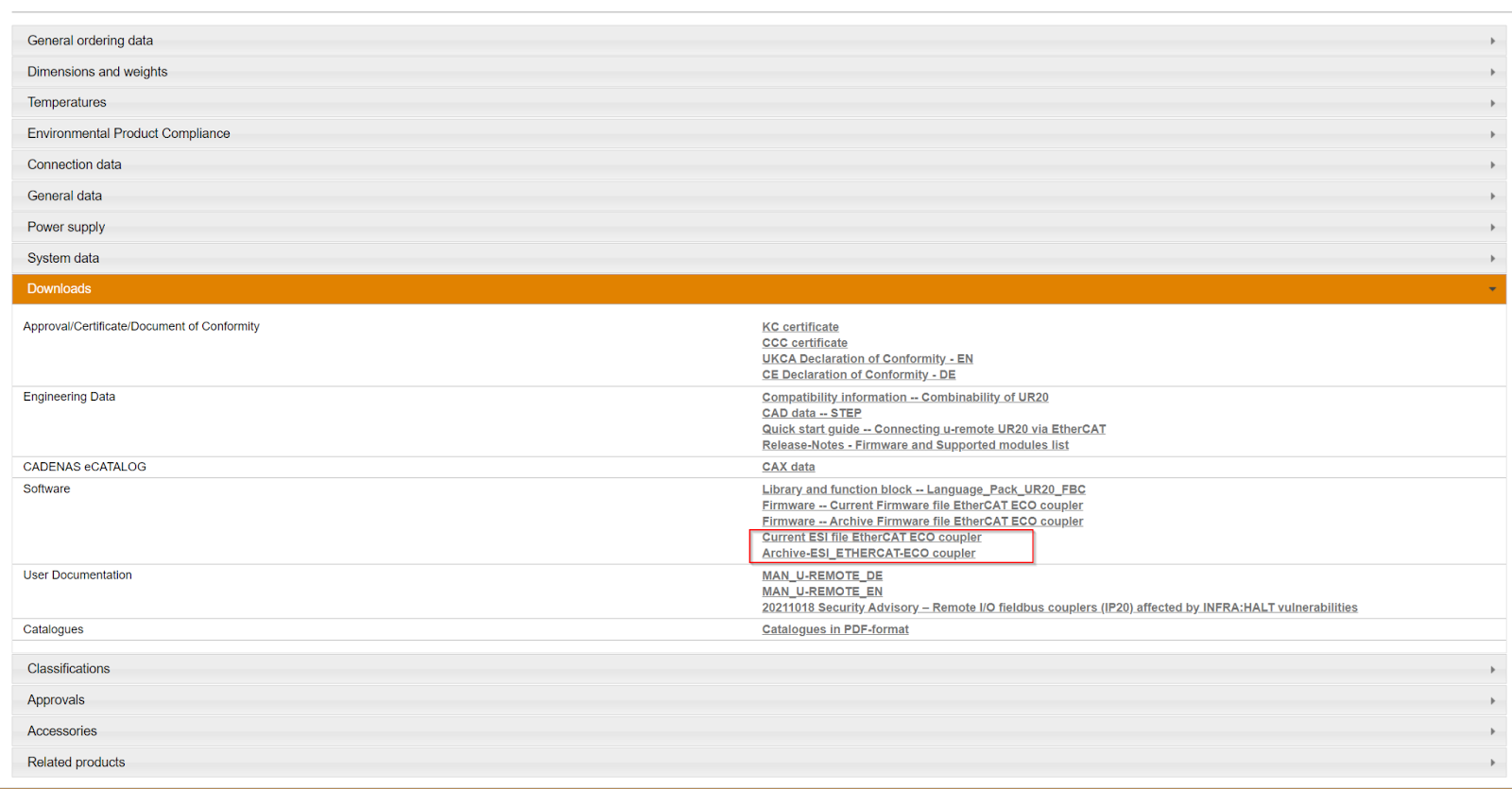
Download ESI File
Download the ESI File from the Link below.
https://catalog.weidmueller.com/catalog/Start.do?localeId=en&ObjectID=2659690000
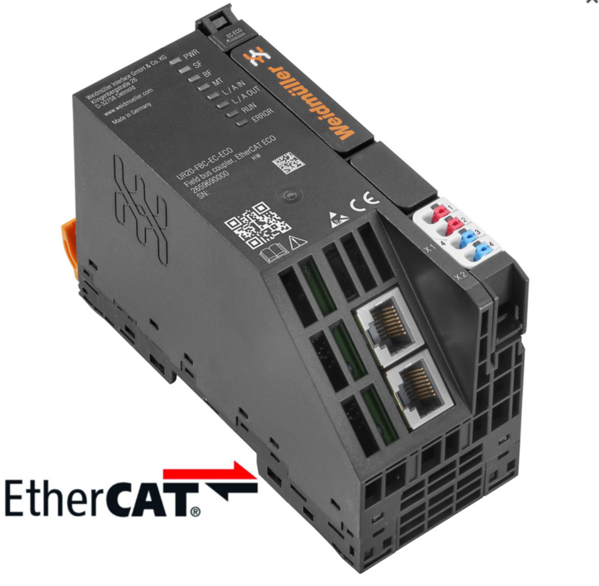
UR20-FBC-EC-ECO?
The UR20-FBC-EC-ECO fieldbus coupler is certified by the EtherCAT Technology Group as an EtherCAT1) participating product. The coupler can connect up to 16 active u-remote modules.
EoE must be enabled on the controller and a valid IP address must be assigned to the coupler in the controller configuration.
It should be noted that the station’s mains power is built into the coupler and power is supplied via a 4-pole connector.
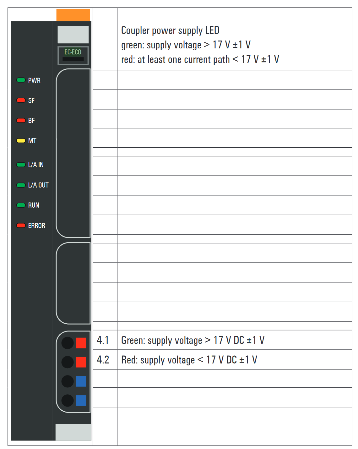
Power Supply
This is the power diagram for the UR20-FBC-EC-ECO.
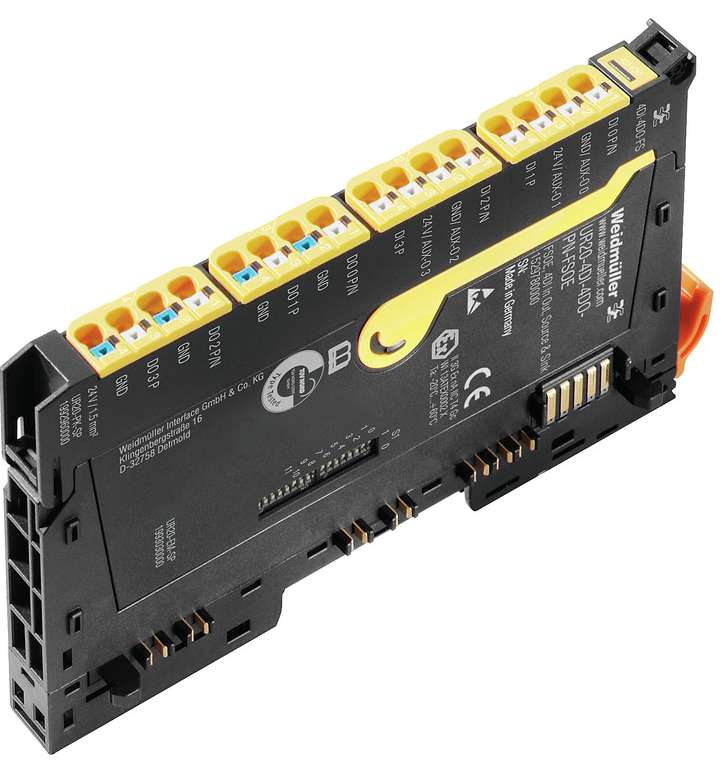
UR20-4DI-4DO-PN-FSOE-V2?
The digital I/O modules UR20-4DI-4DO-PN-FSOE or UR20-4DI-4DO-PN-FSOE-V2 are safety I/O modules for the Fail Safe Over EtherCAT (FSoE) protocol.
Each module provides four digital inputs and outputs respectively, and can detect up to four binary control signals and control up to four actuators at up to 0.5 A each.
The two inputs and outputs can be parameterised for P- or N-switching respectively. Sensors can be connected to connectors 1 and 2 in 2-wire, 3-wire or 4-wire versions.
If the supply current of 0.8 A per plug is not sufficient, the auxiliary output of another module in the same power segment (e.g. potential distribution module) must be used to realize the sensor supply.
The supply of the sensor must be realized using the auxiliary output of another module in the same power segment (e.g. potential distribution module).
Actuators can be connected to connectors 3 and 4 via a 2-wire connection. A status LED is assigned to each channel. The module electronics supply power to the inputs and outputs from the output current path (IOUT).
Test pulse checks on the inputs can be parameterised as cross-circuit detection between input signals and supply voltage, between different input signals or between other signals. Therefore,
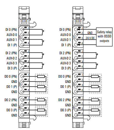
The input is only active when a signal on the dedicated auxiliary output is pending.
If a safety relay with an OSSD output that generates its own test pulse is connected, the test pulse must be deactivated.
Wiring
This is the wiring diagram for the UR20-4DI-4DO-PN-FSOE-V2.
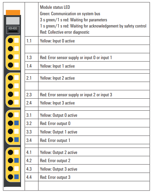
LED
This is the LED status meaning of the UR20-4DI-4DO-PN-FSOE-V2.
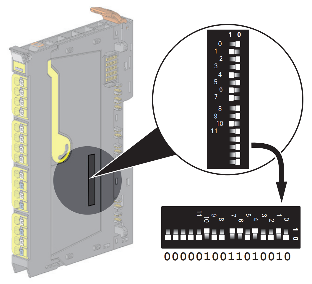
FSOE Address setting
DIP switch for setting the FSoE address next to the UR20-4DI-4DO-PN-FSOE-V2 module.
Implementation
Beckhoff Side
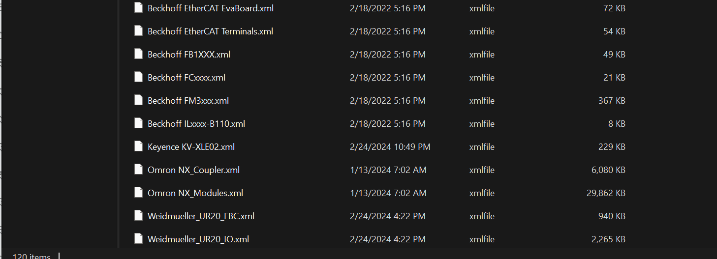
Install ESI File
Store the ESI File downloaded from the weidmueller HP earlier in the following Directory.
C:\TwinCAT\3.1\Config\Io\EtherCAT
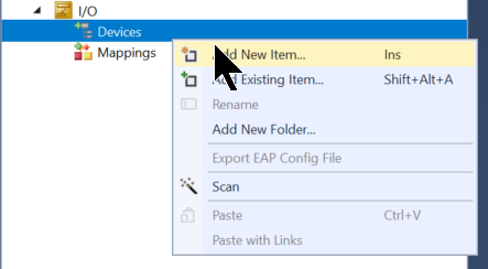
Add EtherCAT Master
To add an EthernetCAT Master, go to I/O>Devices>Right click>Add New Item.
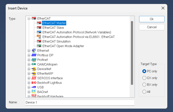
Select EtherCAT>EtherCAT Master and proceed with Ok.
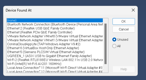
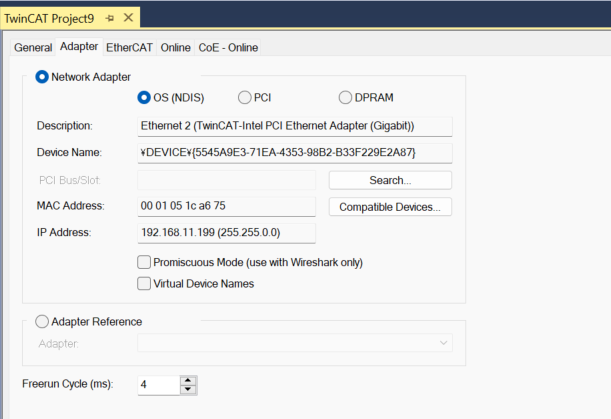
Select the Ethernet Interface to be used as EtherCAT Master and proceed with OK.
Done!
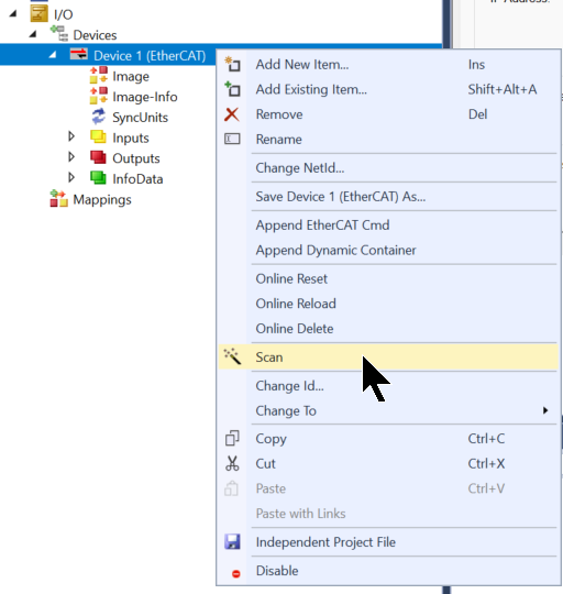
Auto Scan
Use the Auto Scan function to search for EtherCAT Slaves in the network.
Done!You could search for UR20-FBC-EC-ECO.
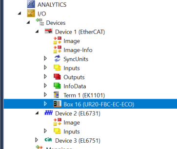
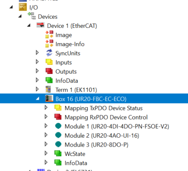
The UR20-4DI-4DO-PN-FSOE-V2 and other modules installed on the UR20-FBC-EC-ECO were also automatically added to the project.
UR20-FBC-EC-ECO Configuration
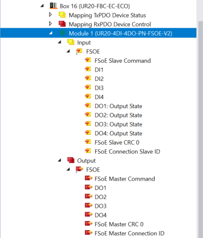
Input/Output Data
The DI/DO signals of the UR20-4DI-4DO-PN-FSOE-V2 used in this project can be mapped directly, etc. The FSoE Master used in this project is the EL6910, but Process IO can be accessed here even when connecting to an FSoE Master from another manufacturer.
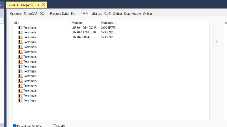
Slot Cofiguration
Also, if there are Slot changes depending on the application, you can use the Tab in Slots to add module configurations, etc.
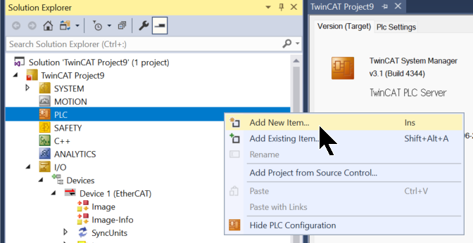
Add PLC
Right-click on PLC>Add New Item to add a new PLC project.
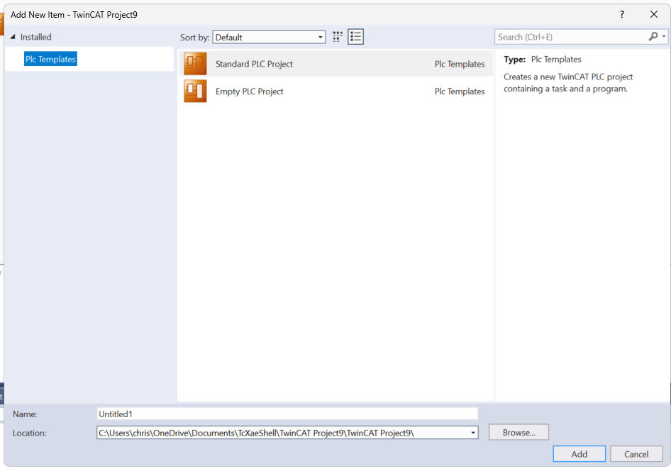
Select Standard PLC Project and proceed with Add.
Add GVL
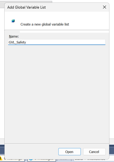
Next, add a Global Variables List to communicate with the Safety project.
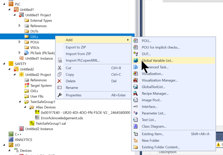
Enter a GVL name and create it.
Declare variables to interact with the Safety project as follows.
| {attribute ‘qualified_only’} VAR_GLOBAL RunStop AT %Q*:BOOL; ErrorAck AT %Q*:BOOL; EStopReset AT %Q*:BOOL; ESTOPStatus ,FBErr ,CommErr ,OutErr ,OtherErr ,FbRun AT %I*:BOOL; END_VAR |
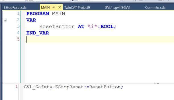
Program
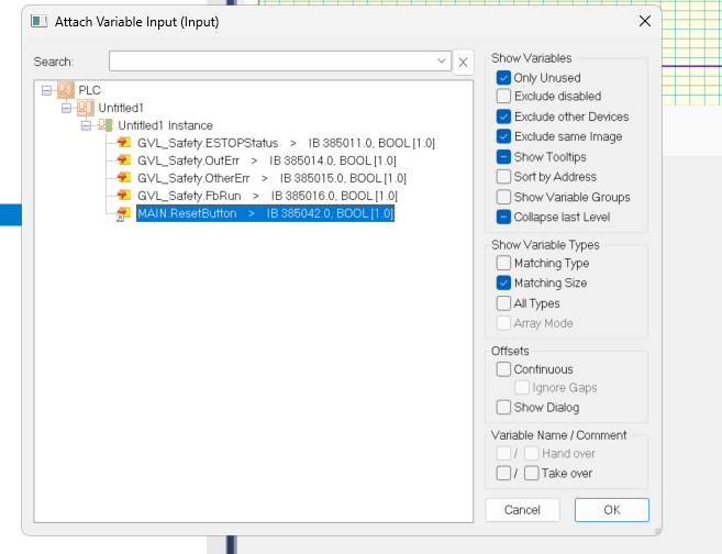
Define a Process Input variable so that the Button for the Emergency Stop Reset is mapped to the actual IO.
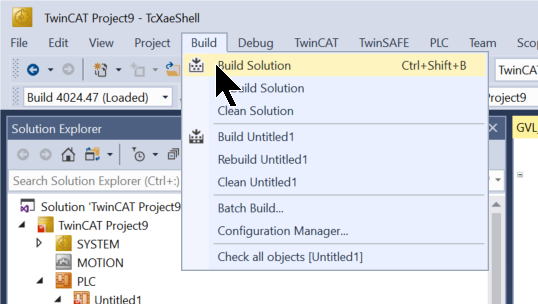
Build
Compile the project under Build > Build Solution.
Map
The EL1088 has been placed in the article this time and Channel 1 is used in it.
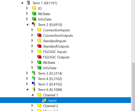
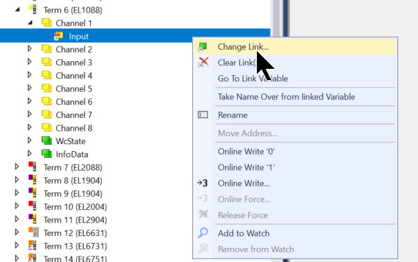
Channel1>Input>Change Link.
Set the variables you defined in the Main program earlier.
Add Safety Project
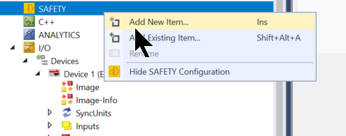
In this case, EL6910 will be used, so add a new Safety project under Safety>Add New Project.
Select TwinCAT Safety Project Preconfigured ErrAck and proceed with >Add.
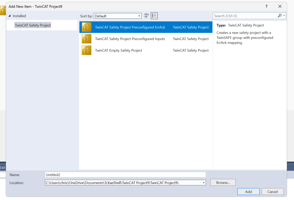
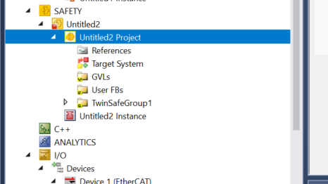
Done!New Safety projects have been added.
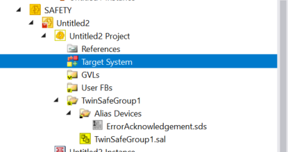
Setup Target System
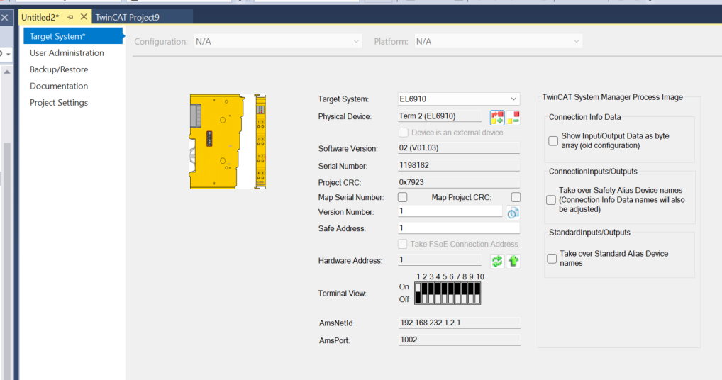
Configure the EL6910 under Project>Target System.
This is the FSOE Master settings screen.

Target System
Set the EL6910 used in this article from the Drop-List of the Target System.

Next, click on Physical Device.
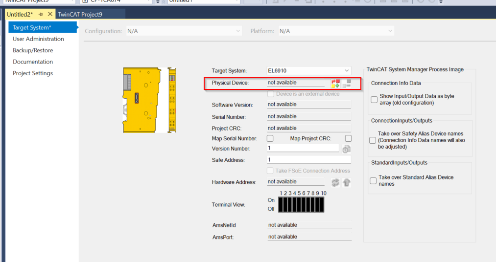
Select the EL6190 that you have just searched for with the TwinCAT auto-scan function.
Done!
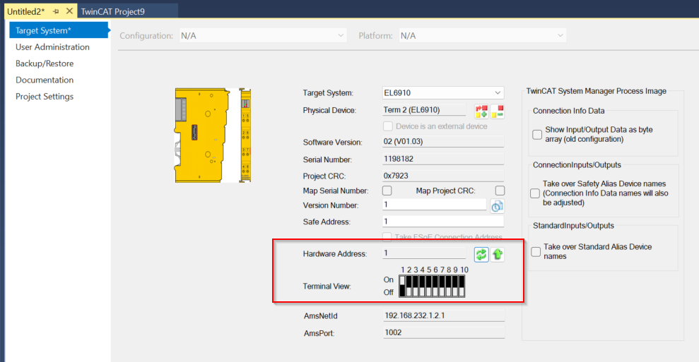
Hardware Address
The next step is to set the FSOE address of the EL6910; there is also a DIP switch next to the EL6910 where the address can be set.
Add FSoE Connection
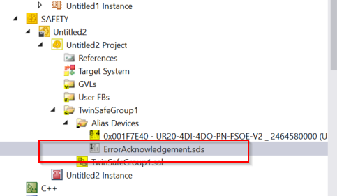
Next, to add Weidmueller’s UR20-4DI-4DO-PN-FSOE-V2 module to the Safety Group, click Alias Devices>Right click>Add>New Item.
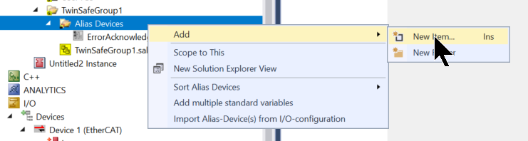
Add Safety>EtherCAT>UR20-4DI-4DO-PN-FSOE-V2.
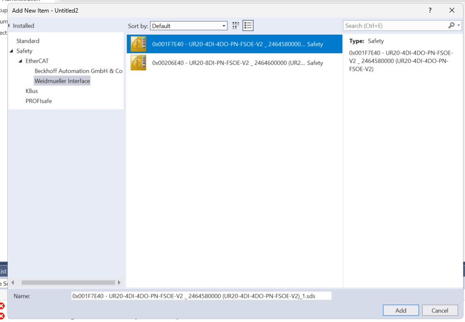
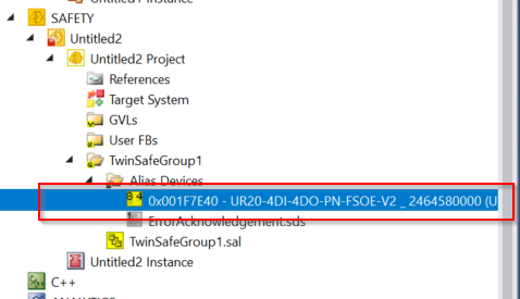
Done!UR20-4DI-4DO-PN-FSOE-V2 has been added.
Configuration
Continue with the configuration of the UR20-4DI-4DO-PN-FSOE-V2.
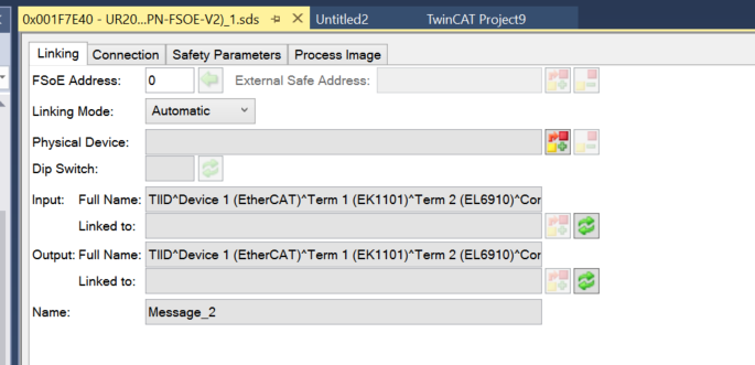
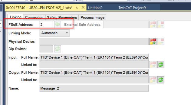
FSoE Address
The FSoE address should be entered according to the DIP switch next to the module.
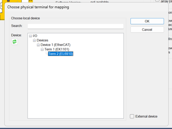
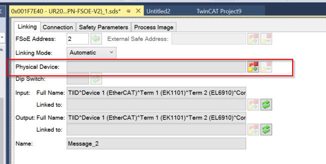
Physical Device
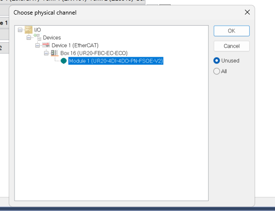
The next step is to configure the Physical Device. This means that this Safety EtherCAT Connection specifies which UR20-4DI-4DO-PN-FSOE-V2 is used within the EtherCAT network.
Select UR20-4DI-4DO-PN-FSOE-V2 >OK.
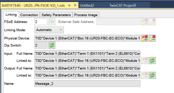
Done!
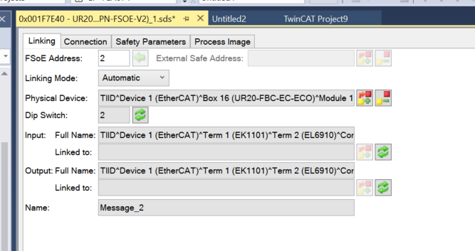
Once the project is saved, the Input/Output is also automatically updated.
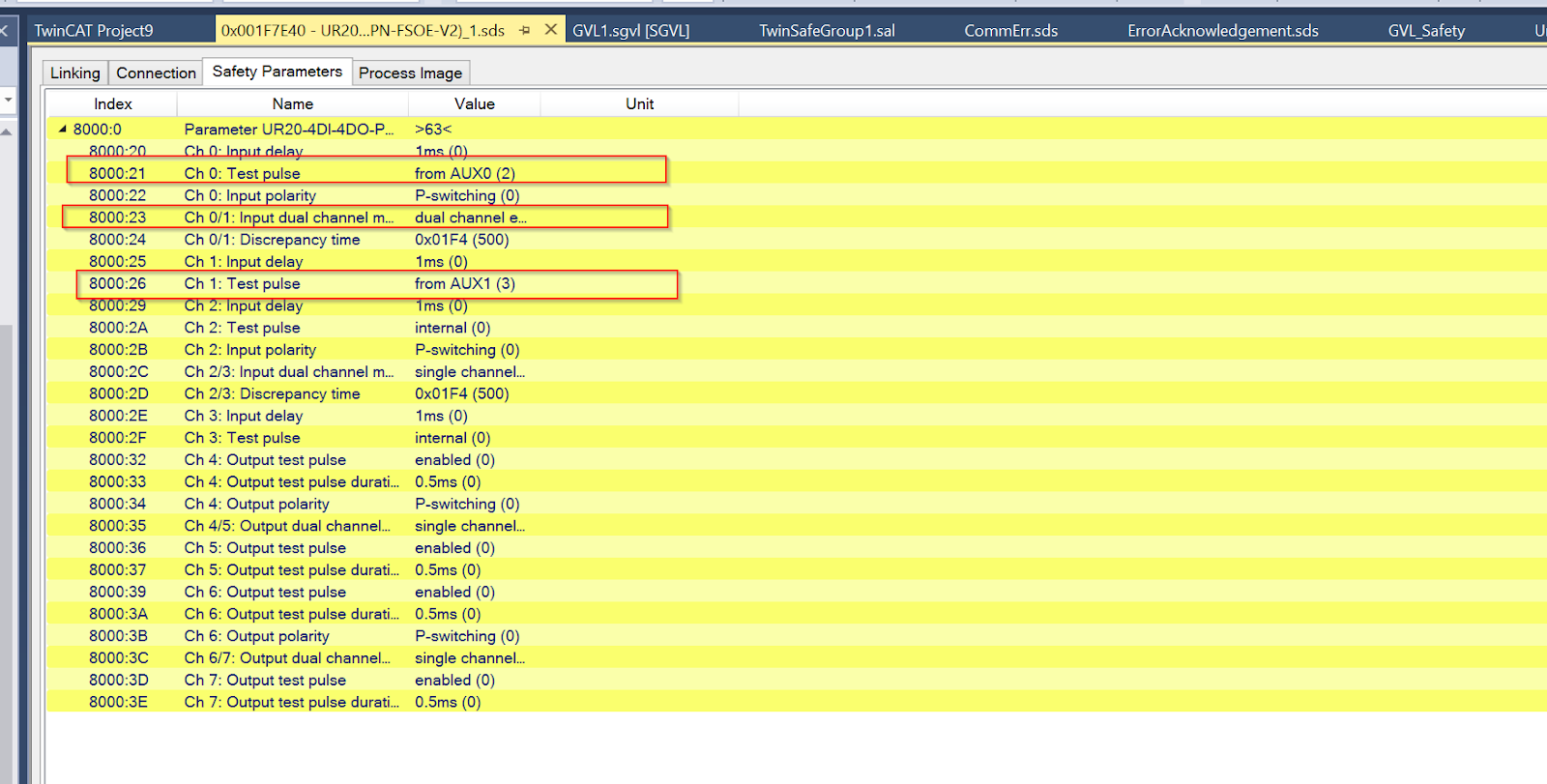
Safety Parameters
The parameters of the module should also be set according to the application.
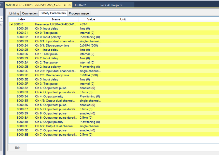
This time, use the 1-to-2 emergency stop input and use Test Input on AUX0 and AUX1.
Add Alias Devices
Now define the variables to interact with the Normal PLC project.
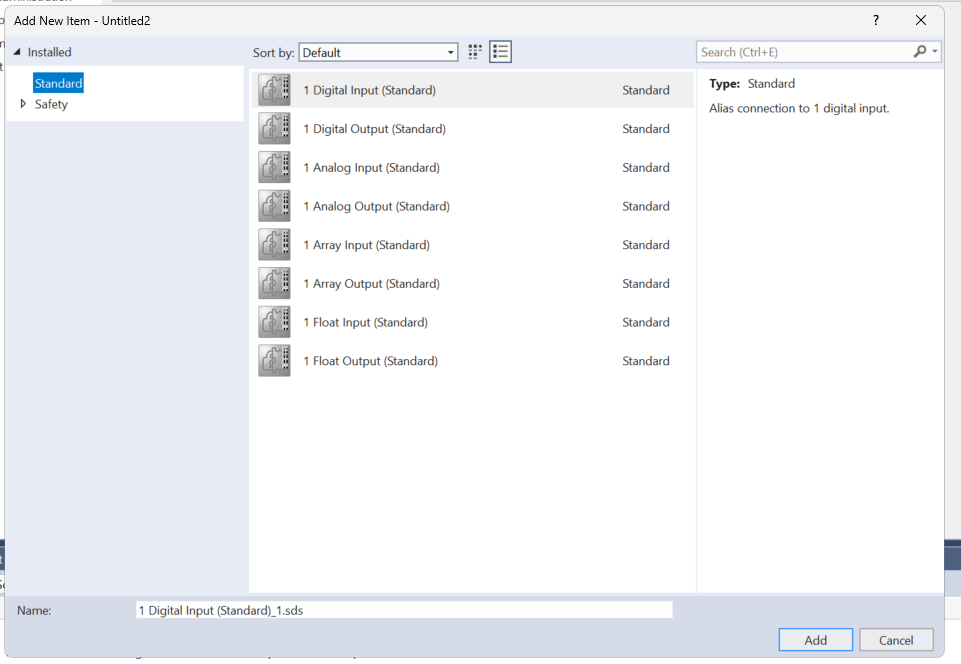
Alias Devices>Right click>Add>New Item.
1Select Digital Input (Standard) and add it with >Add.
Mapping
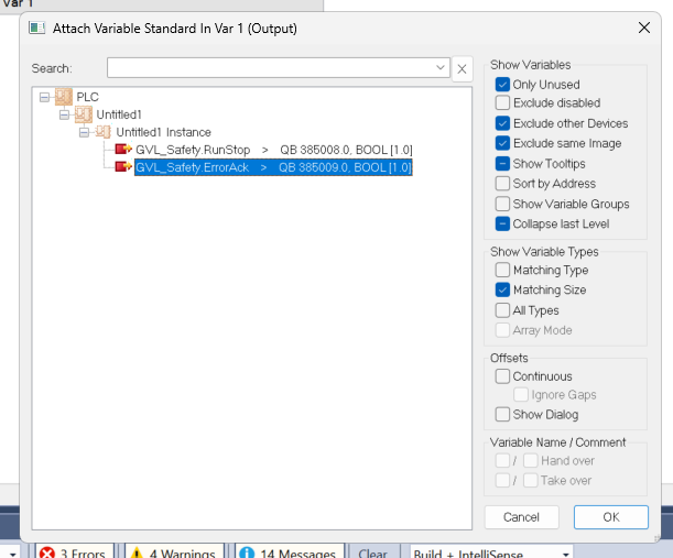
The next step is Mapping the Normal variable.
Click on Linked To.
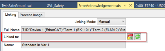
Mapping with the variables you have just defined in the PLC project.
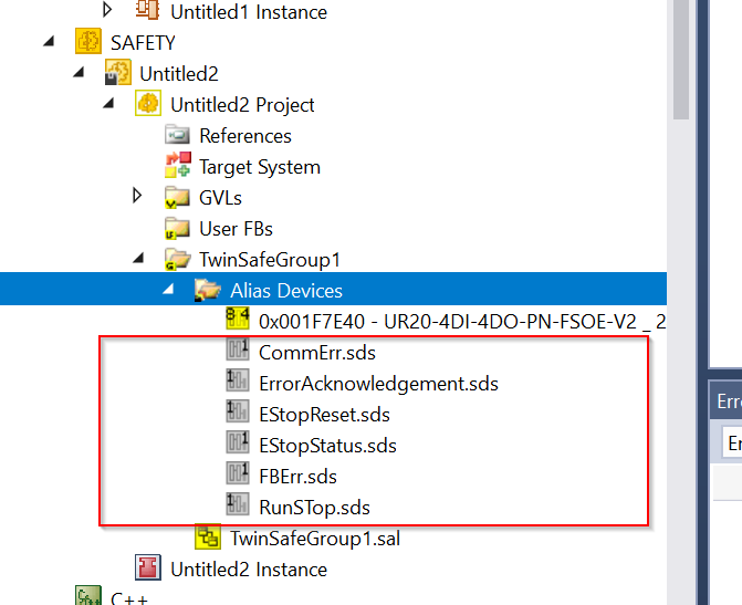
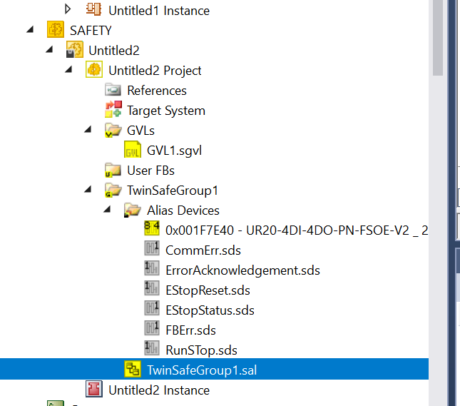
Add Other Alias
Use the same operation to define Input/Output variables and Mapping them to variables in the Normal PLC project.
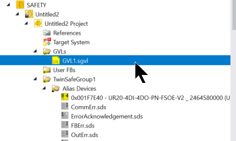
Add GVL
Now add a Global Variable List to the Safety project.
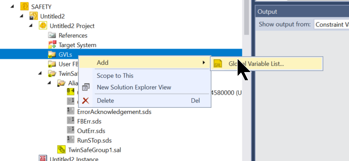
GVL is added.
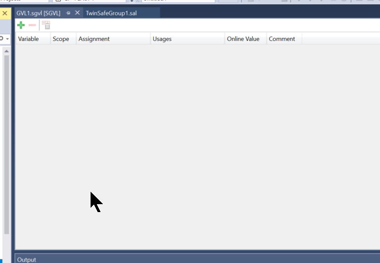
This is the edit screen of the Safety GVL.
Mapping
Please map all variables to match the application.
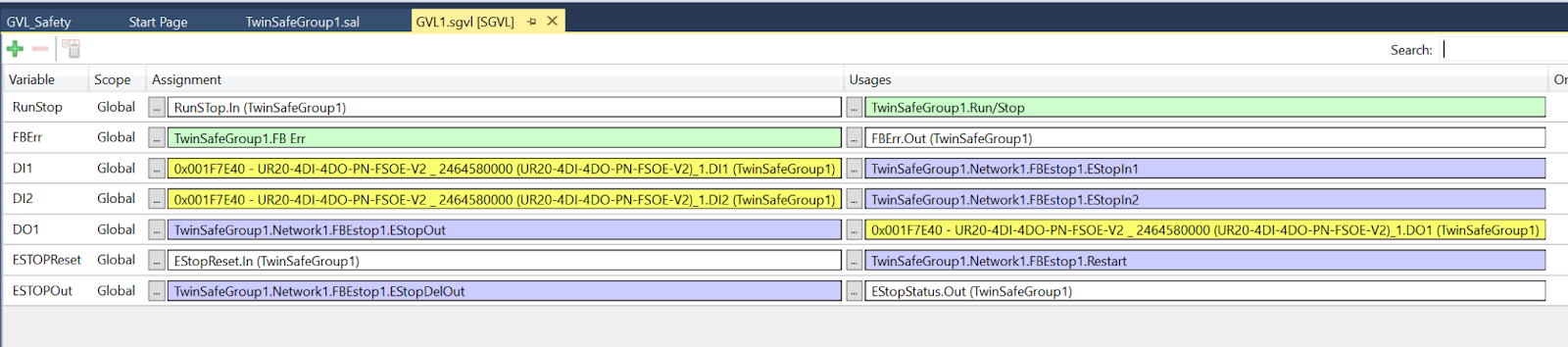
This is a Normal PLC and INPUT/OUTPUT Mapping.
Safety Project
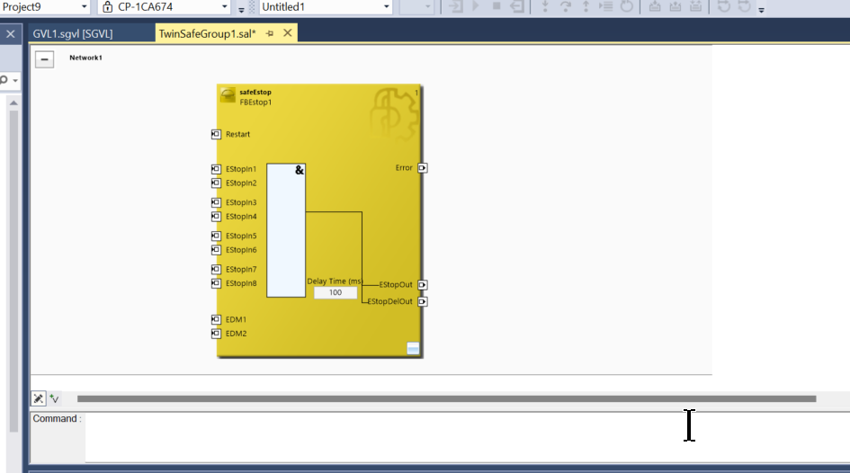
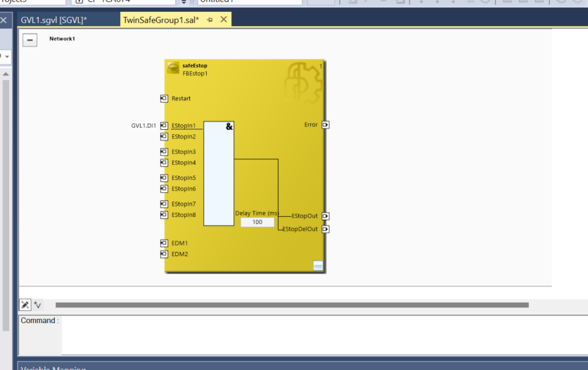
The final step is to create a Safety programme.
Add safeEstop Function Block to FunctionBlocks(boolean).
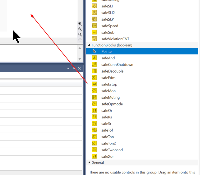
Done!
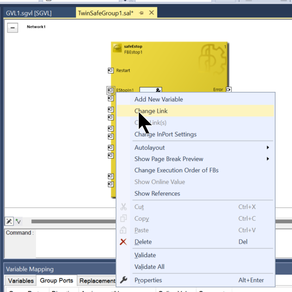
Link Input
To link a variable to EStopIn1 in the Function Block, right-click EStopIn1 > Change Link.
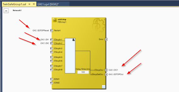
Connect to the digital inputs on the Weidmüller UR20-4DI-4DO-PN-FSOE-V2.
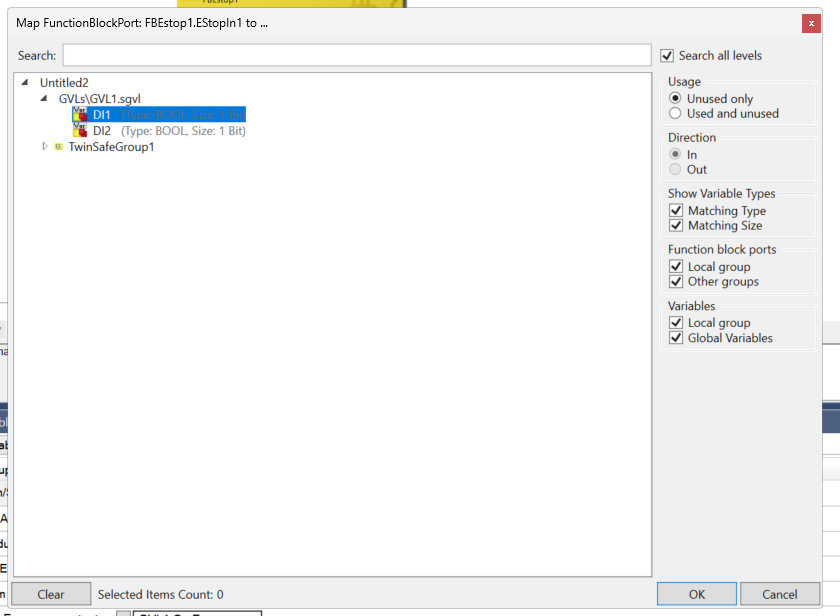
Done!
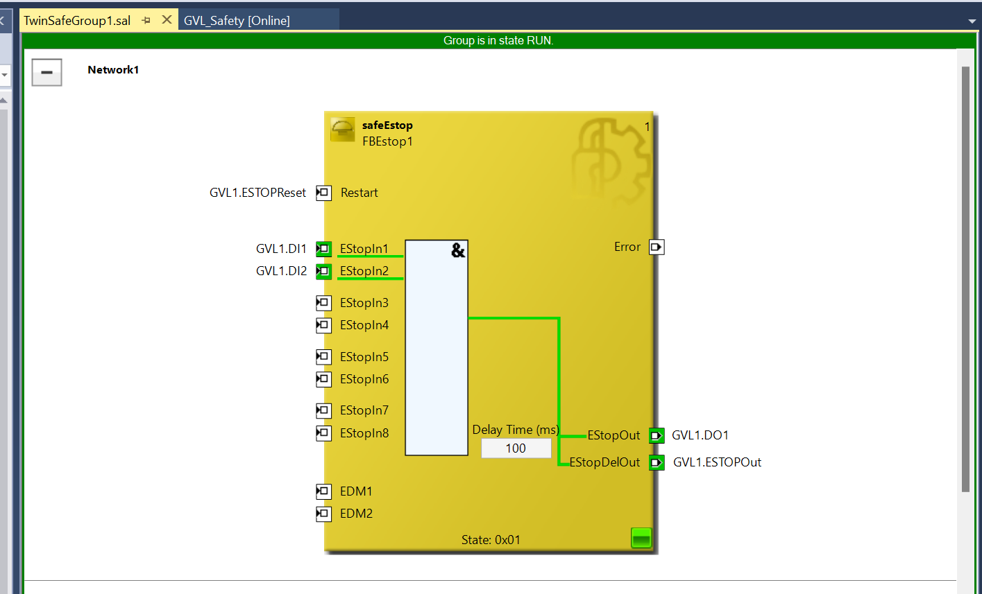
As shown in the diagram below, the ESTOP input, output signal and reset signal are also connected.
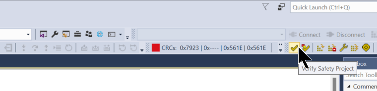
Build
Compile the Safety project and check for errors.
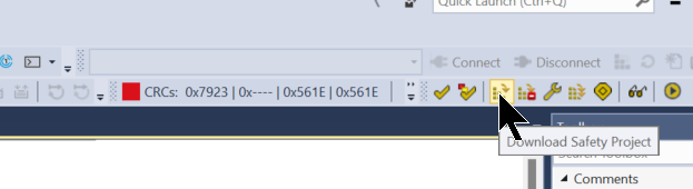
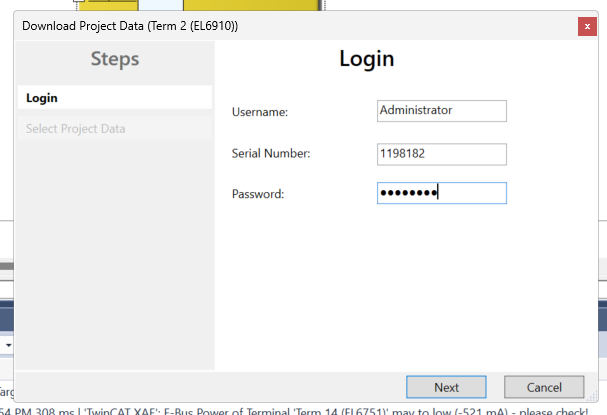
Click on “Download Safety Project” to download the Safety project to the EL6910.
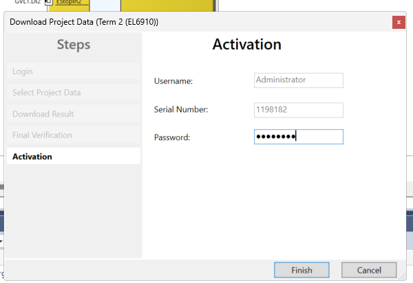
Also enter the User Name, EL6910 serial number and EL6910 Password.
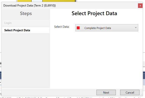
Download Complete Project Data.
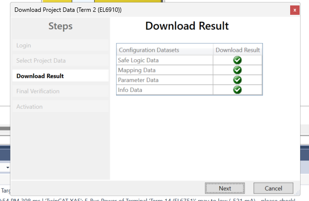
Check the Download results and proceed with Next.
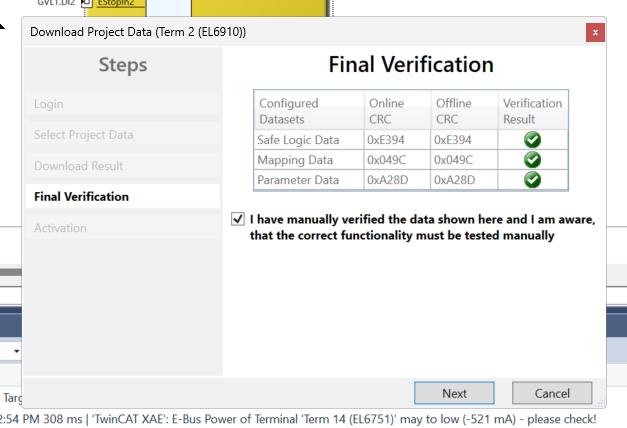
Checkbox and press Next to proceed.
Enter the Password one more time and activate the Safety project.
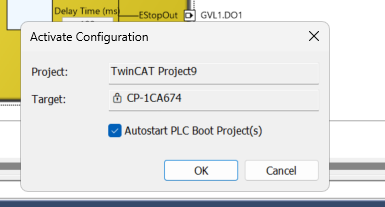
Activate Configuration
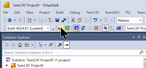
Finally, click Activate Configuration to download the Hardware Configuration, etc.
OK to proceed.
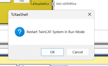
Shift to Run Mode.
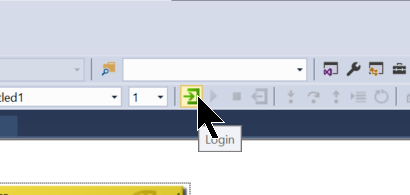
Login
Login to the project.
Result
Issue the ErroAck down signal to reset the Safety Group. Afterwards, the RunStop signal should be set to True and the Safety Group should be executed.
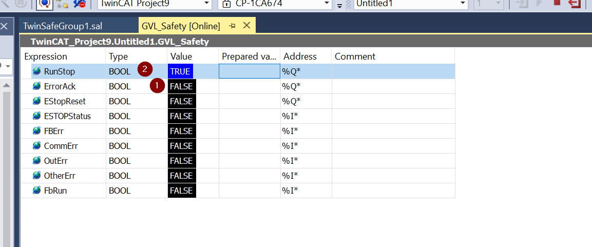
Done!Now Safety Group is running Run.
The UR20-4DI-4DO-PN-FSOE-V2 is now also lit green and the UR20-FBC-EC-ECO EtherCAT Coupler is also error-free.
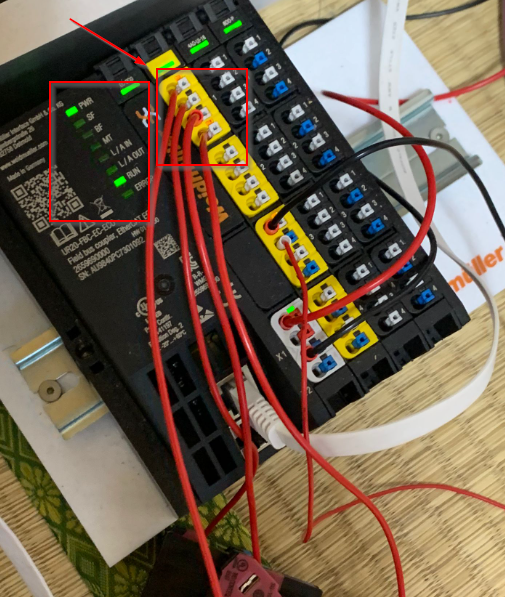
Only the emergency stop and lamp are connected, but you can see the actual operation in the video below.