
のちほど翻訳させて頂きます
First, What is CClink?
Here is the information from Wiki:
CC-Link is an open-architecture network that was originally developed by the Mitsubishi Electric Corporation in 1997.
CC-Link is open industrial network that enables devices from numerous manufacturers to communicate. It is predominantly used in machine, cell or process control applications in manufacturing and production industries, but can also be used in facilities management, process control and building automation.
Simply, it is a method to be easier to communicate between PLC and other devices.While you would like to receive 20 XY from other PLC, it is not a easy job because there are so many hardware work and you need to correct the electrical drawing…etc. But using CCLink, you do not need to do these stuff and just install a CCLink module and programming. And this time i will show how to make the program by defining a FX5U PLC in a Slave station and receive the data from the master.
Which Module should you choose?
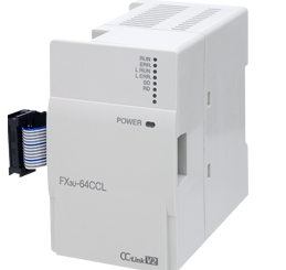
Here is the CCLink Module that for the slave station that I chose for this application.
If you are using FX5U PLC, “FX5-CNV-BUS” is necessary. And also only one FX3U-64CCL can be connected with One PLC.
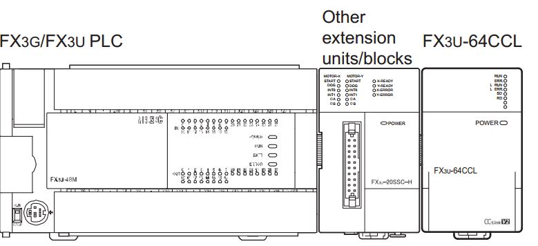
Configuration Example
Station and Communication Setting
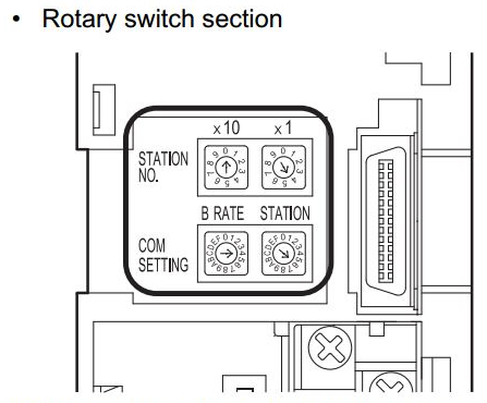
STATION NO : Set the station numbers.
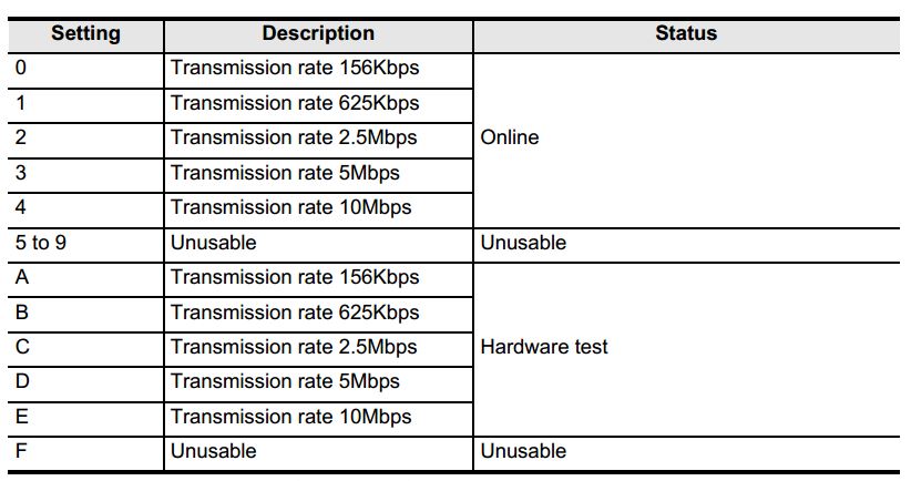
COM SETTING: Set the Brand rate.
Programming
By using this module, Only two instructions that you need to take care. But in here, I would like to explain what is “Buffer Memory”.
Buffer Memory
It is a memory area that in the module and you can using the instruction inside the program to write/read them.
FROM

These instructions read (n) words of data from the buffer memory specified by (s) in intelligent function module specified by (U/H), and store the data to the device specified by (d) and later (d).
TO
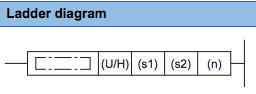
These instructions write the (n) points of data in the device starting from the one specified by (s2) to the buffer memory address specified by (s1) in intelligent function module specified by (U/H).
Buffer Memory(BFM) Tables that normally use
#0 to #7 is operated by Bit.
#8 to #23 is operated by word.
#25 is using to get the communication status of master and slave.
#29 is using to get the status from modules.
Ladder Program
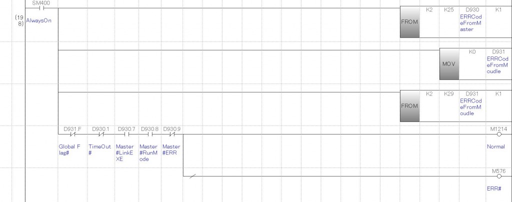
Here is a Ladder program to get the data from the master.
Line1//Access BFM#25 at station 2 to get the communication status, save as D900.
Line2//reset the module receive D931.
Line3//Access BFM#29 at station 2 to get the Error code from modules, save as D931.
Line4//Make sure master and slave are all in good condition.*Please refer the manual
Line5//If condition is good, OutputM1214.
Line6//if not, Output M576.
It is very simple, right?;).
By using CCLink, you can easily to make a master station to do the remote control of other local machine by sending the I/O status.
*Make sure to reset all the status at zero while having a communication ERROR.
See u next time~!