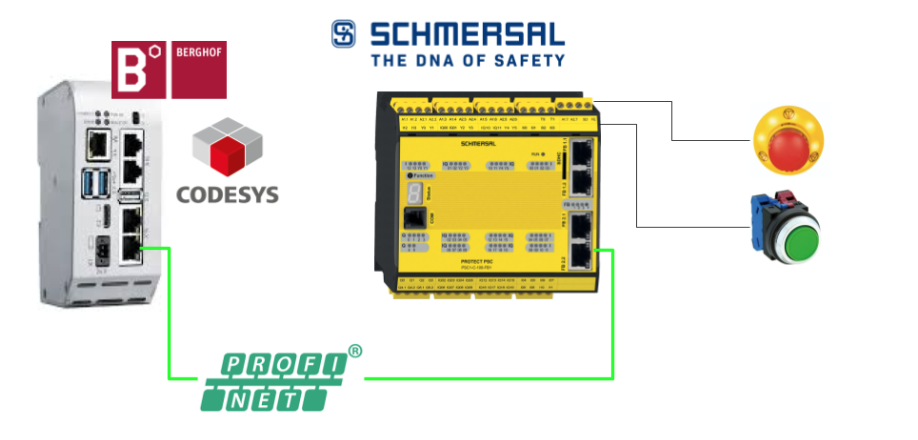
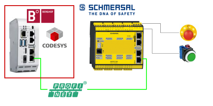
This is a new series, in which various articles will be developed using the PSC1-C-100-FB1 Safety Controller from Schmersal. Episode 3 explains how to build up Profinet communication with the Berghof Codesys Controller.
Come on, let’s enjoy FA.
Foreword
Thank you from the bottom of my heart for visiting my technical blog and YouTube channel.
We are currently running the “Takahashi Chris” radio show with Full-san (full@桜 八重 (@fulhause) / X) which I deliver every Wednesday night.
Sharing, not hoarding, technical knowledge
We publish technical information related to factory production technology and control systems for free, through blogs and videos.
With the belief that “knowledge should be accessible to everyone,” we share practical know-how and real-world troubleshooting cases from our own field experience.
The reason we keep it all free is simple: to help reduce the number of people who struggle because they simply didn’t know.
If you’ve ever thought:
- “Will this PLC and device combination actually work?”
- “I’m having trouble with EtherCAT communication—can someone test it?”
- “I want to try this remote I/O, but we don’t have the testing environment in-house…”
Feel free to reach out!If lending equipment or sharing your configuration is possible, we’re happy to verify it and share the results through articles and videos.
(We can keep company/product names anonymous if requested.)
How can you support us?
Currently, our activities are nearly all unpaid, but creating articles and videos takes time and a proper testing environment.If you’d like to support us in continuing and expanding this content, your kind help would mean a lot.
Membership (Support our radio show)
This support plan is designed to enhance radio with Mr Full.
https://note.com/fulhause/membership/join
Amazon Gift List (equipment & books for content production)
Lists equipment and books required for content creation.
https://www.amazon.co.jp/hz/wishlist/ls/H7W3RRD7C5QG?ref_=wl_share
Patreon (Support articles & video creation)
Your small monthly support will help to improve the environment for writing and verifying articles.
https://www.patreon.com/user?u=84249391
Paypal
A little help goes a long way.
https://paypal.me/soup01threes?country.x=JP&locale.x=ja_JP
Just trying to share things that could’ve helped someone—if only they’d known.
Your support helps make knowledge sharing more open and sustainable.
Thank you for being with us.
soup01threes*gmail.com
Technical knowledge shouldn’t be kept to ourselves.
Reference Video
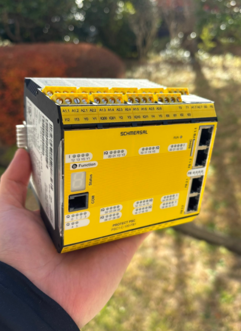
Schmersal.Open box with PSC1-C-100-FB1!
Reference Link
http://soup01.com/en/category/schmersal_en/psc1-en/
Fieldbus with PSC1 Controller
Ethernet-based fieldbus is available here.
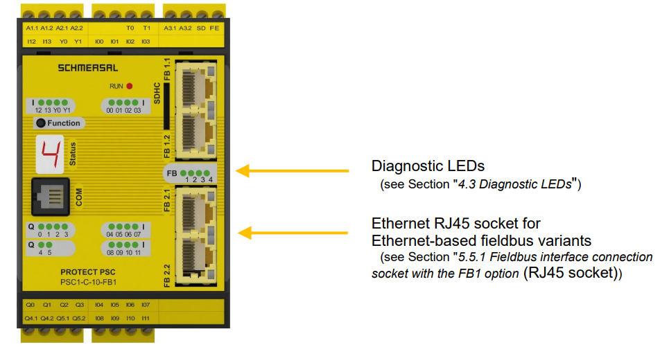
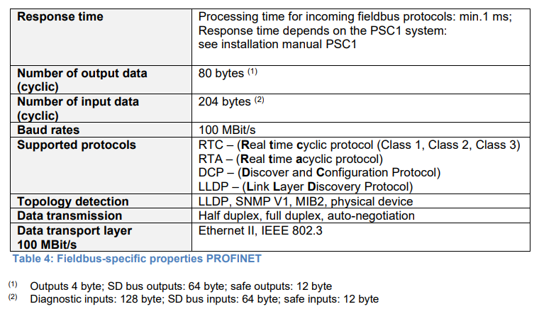
Profinet
This is the specification when used as Profient IO Devices with PSC1-C-100-FB1.
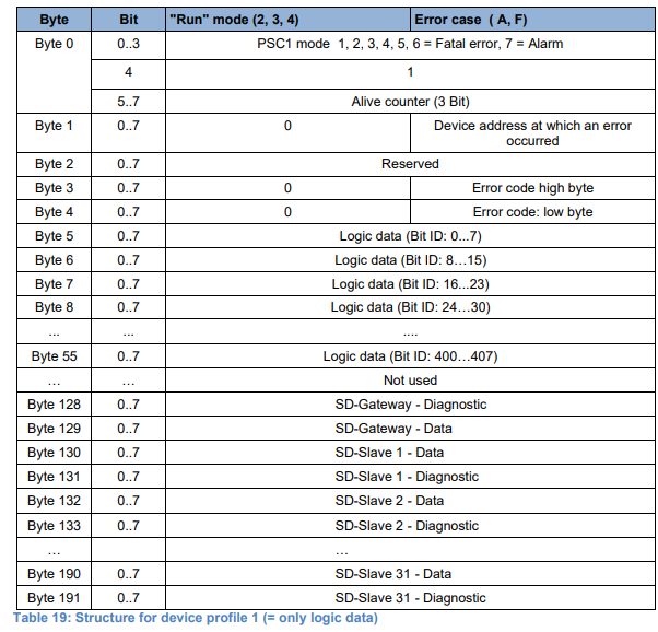
Device Profile
This is the input Mapping for Profinet Profile 2 of the SCHMERSAL PSC1-C-100-FB1.
This is the output Mapping of Profinet Profile 2 of the SCHMERSAL PSC1-C-100-FB1.
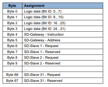
Non-Safe Usage Object
For the first time in this article, a logic input/output data component was used: for non-safety-related communication from PSC1 to a higher controller, the PSC1-C-10 provides 55 bits and the PSC1-C-100 up to 408 bits (depending on the selection).
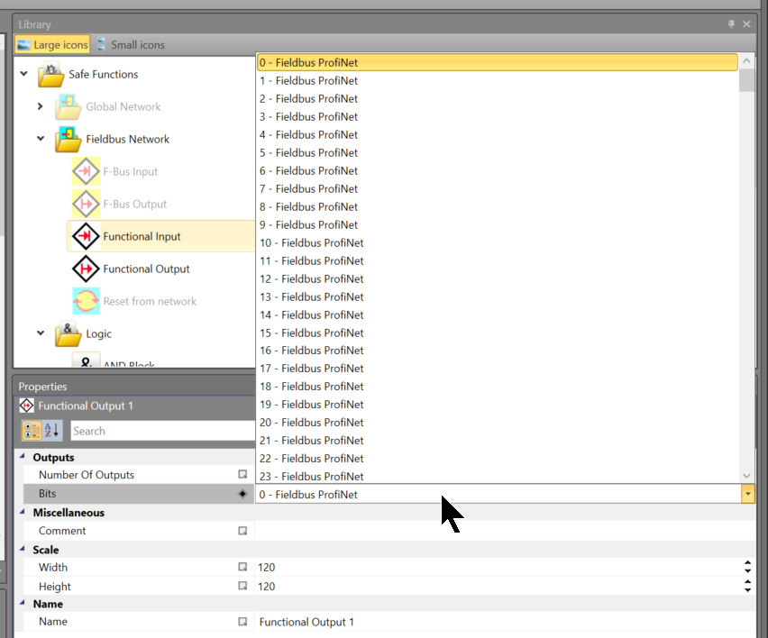
Functional Inputs
Functional Input can only be used once” and the ‘Number of Inputs’ property for each functional block can be set in the range 1-32.
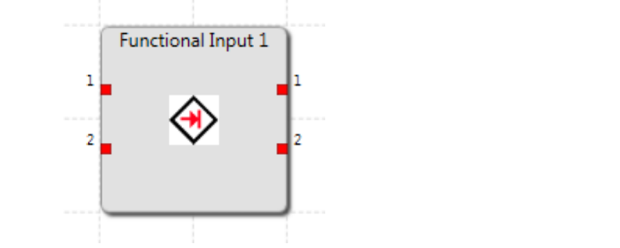
Functional Inputs allow non-safety-related signals from a higher-level controller to be used in SafePLC2 applications. Note that in accordance with DIN EN 13849-1, chapter 4.6.3, there must be no logical linkage of safety and non-safety signals that may reduce safety integrity.
The designer of the safety application is responsible for ensuring this. SafePLC2 forces Functional Inputs to ‘and’ link with other signals.
This makes it clear already in the design that the corresponding inputs have to be specially processed and facilitates application validation.
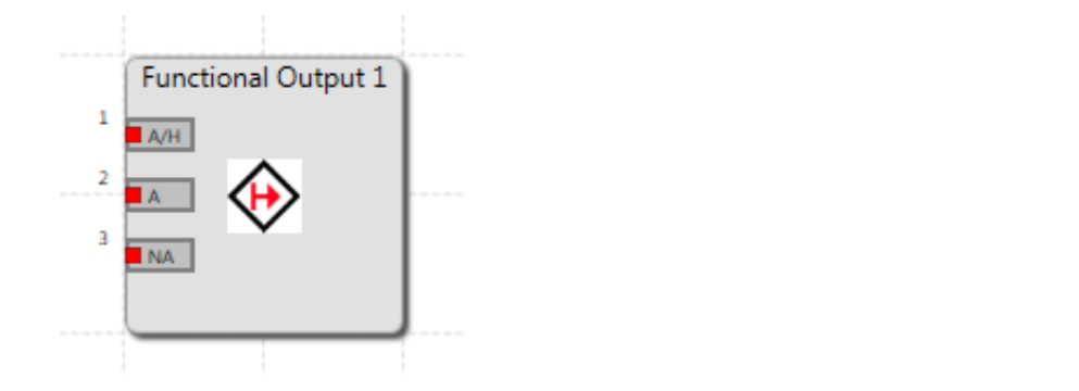
Functional Outputs
Functional Outputs can only be used once. The number of outputs for each block can be set from 1 to 55 for the PSC1-C-10 series and from 1 to 408 for the PSC1-C-100 series. The diagram below shows a function output block with three connectors. Each connector can also be set individually.
Implementation
This is the structure of this article.
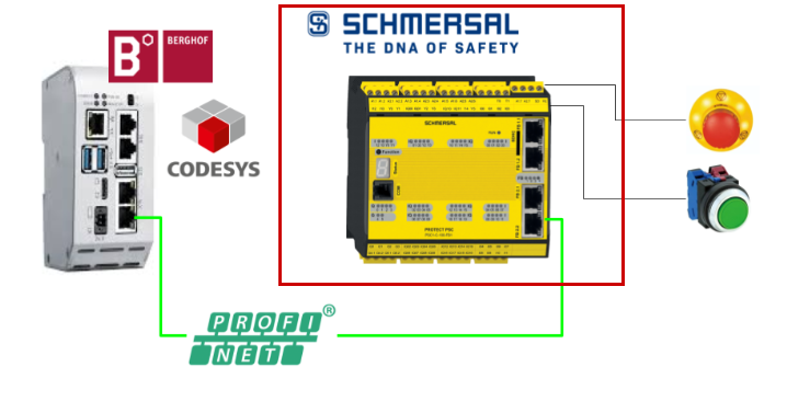
Schmersal Side
Start with the PSC1-C-100-FB1 Safety Controller on the SCHMERSAL side first.
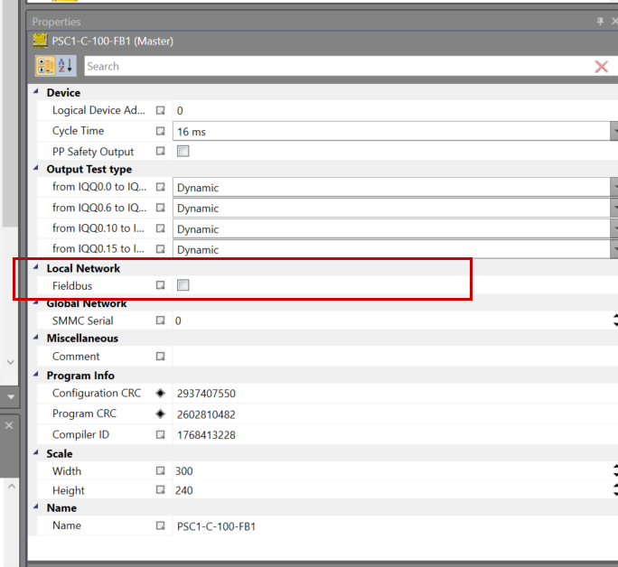
Activate Fieldbus
Select Controller to enable Interface for Profinet IO Devices.
Put the Local Network>Fieldbus Checkbox in the Properties of the PSC1-C-100-FB1 Safety Controller.
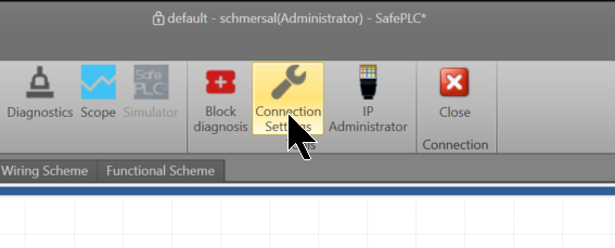
Configure Profinet
An item called Fieldbus ProfiNet has been added to the Local Network on the left-hand side of the SafePLC2 tool.
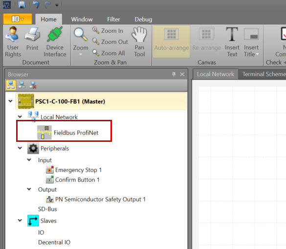
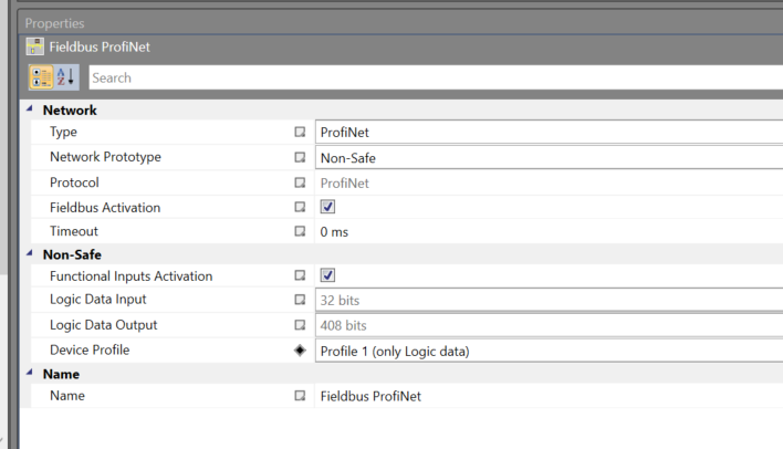
In the Properties of the Fieldbus ProfiNet, you will find items such as connection settings.
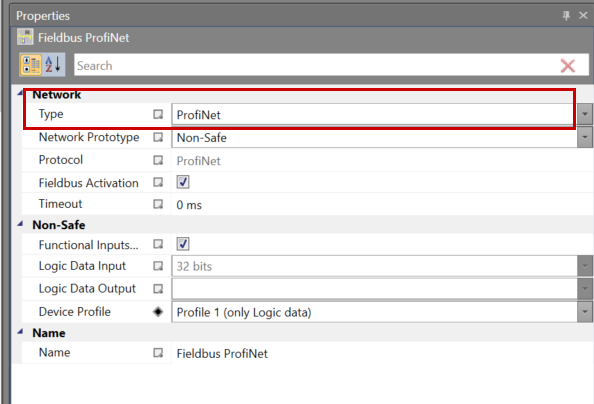
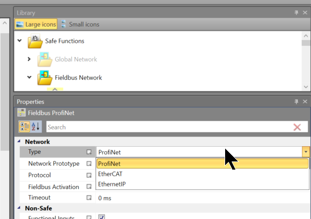
Type
This selects the Fieldbus type of PSC1-C-100-FB1 Safety Controller.
Either Profinet, EtherCAT or EthernetIP can be configured.
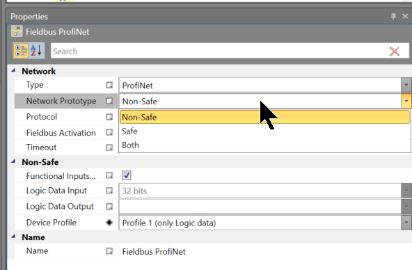
Network Prototype
Either Profinet, EtherCAT or EthernetIP can be configured.
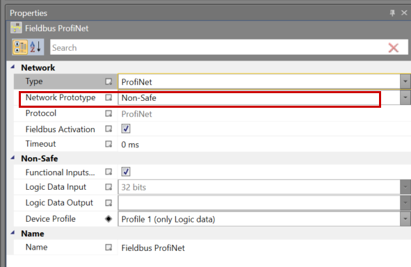
This time, set Non-Safe to Network Properties as you are building Non-Safety Profinet communication.
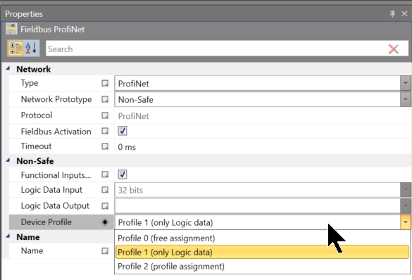
Device Profile
Here you can set the type of data exchange when communicating with a higher level.
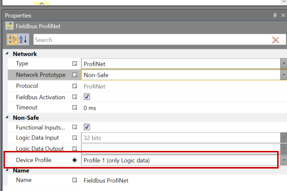
In this article, it will be set to Profile1 (Only Logic data); for Data Mapping, refer to the table introduced earlier.
IP Configuration
To establish Profinet communication, the device name of the Profinet IO Devices (SCHMERSAL PSC1-C-100-FB1 in this article) must match the Profinet IO Controller settings.
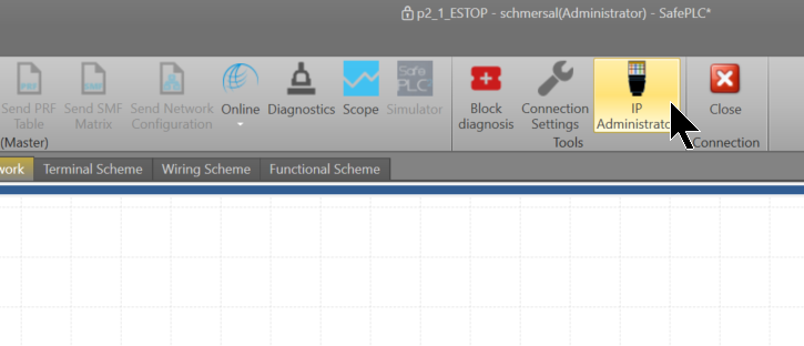
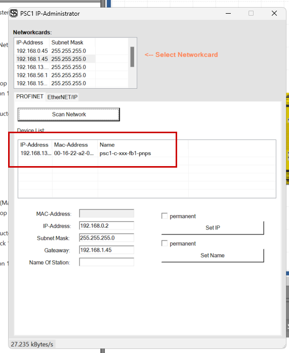
This is the Profinet tool for SafePLC2.
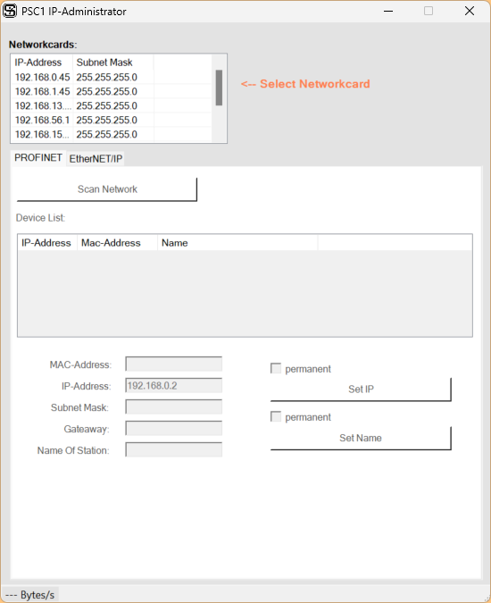
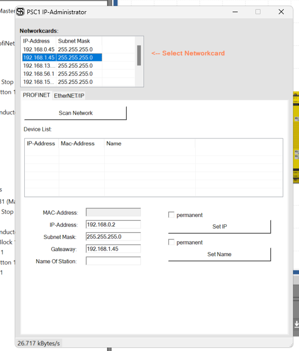
Select Networkcards
First configure the Network card to search for PSC1-C-100-FB1.
Scan Network!
Next, click on the ‘Scan Network’ button.
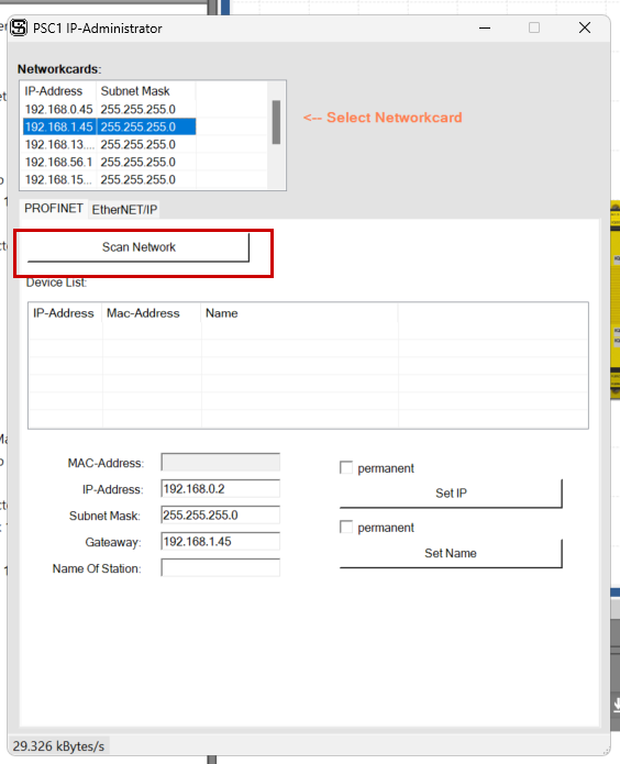
Done!PSC1-C-100-FB1 Safety Controller displayed.
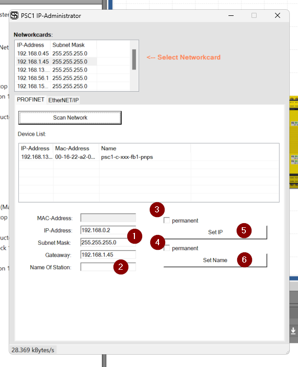
Assign Name/IP
Finally, set the IP address and device name according to your application.
To reflect these settings, run “Set IP” and “Set Name” separately.
Also, to store these settings in non-volatile memory, please tick the “permanent” checkbox.
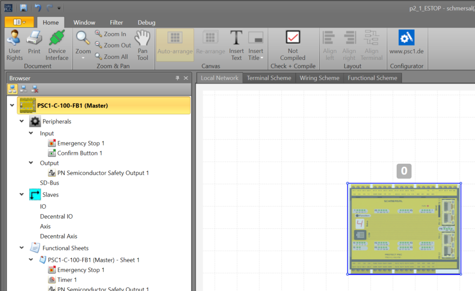
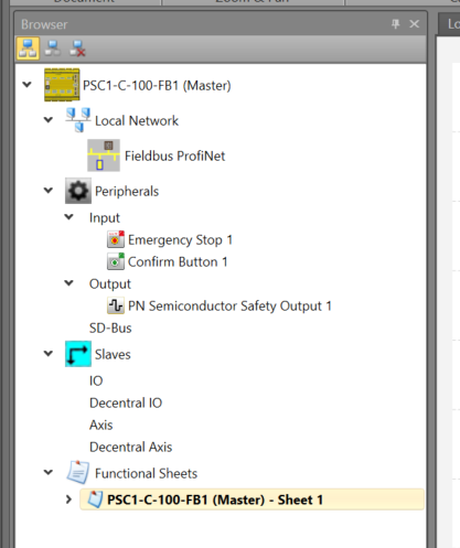
Program
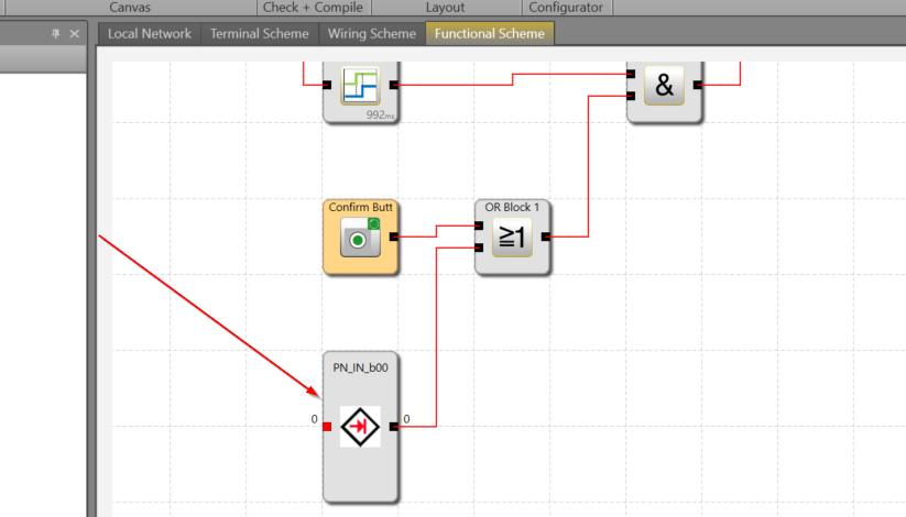
Now open Functional Sheets to create a safety programme.
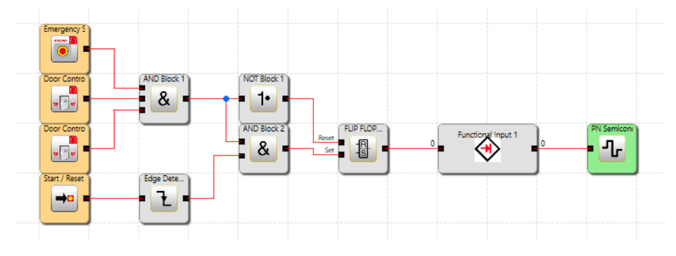
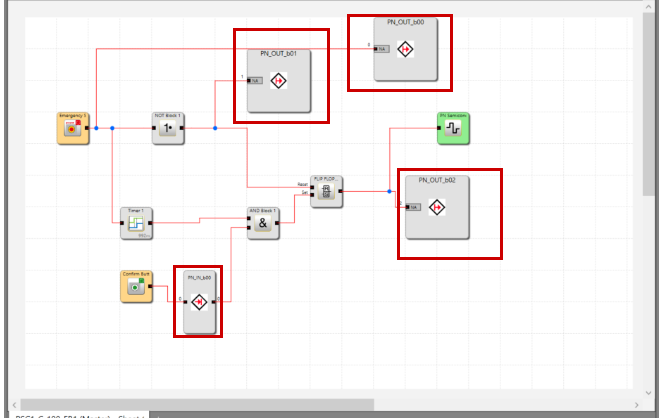
This is the safety program created in this article. It is the same as the previous one, with the addition of the part that sends data back to the upper Controller via Profinet.
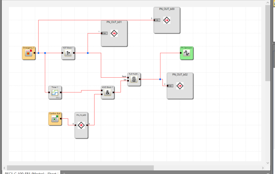
This is an additional section.
- Emergency stop TRUE signal → transmitted to Profinet IO Controller
- Emergency stop FALSE signal → sent to Profinet IO Controller
- Emergency stop TRUE and reset OK signal → sent to Profinet IO Controller
- Remote reset from Profinet IO Controller -> transmitted to PSC1-C-100-FB1
Use Fieldbus Data
To use Fieldbus Data, add Functional Input and Functional Output from the Library to your project.
- Functional Input: input data received via Fieldbus
- Functional Output: Output data sent via Fieldbus
You can also set the Fieldbus memory Offset in the Bits section.
Next, the Functional Input is set to “Top input” by default.
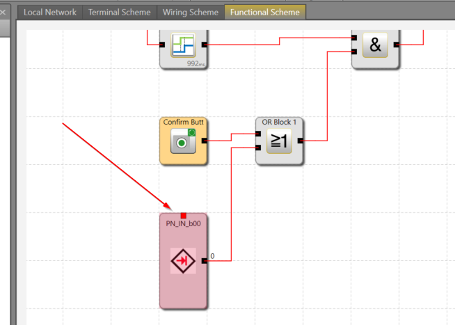
The position of the Connector can be changed via the “Use top input connector” Checkbox.
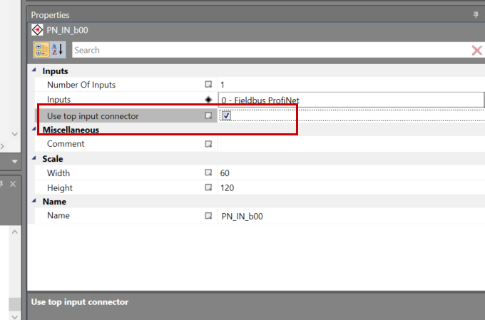
Done!
Connect to the Controller
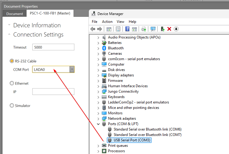
Connect the COM Port of the PSC1-C-100-FB1 and the dedicated cable to the PC.
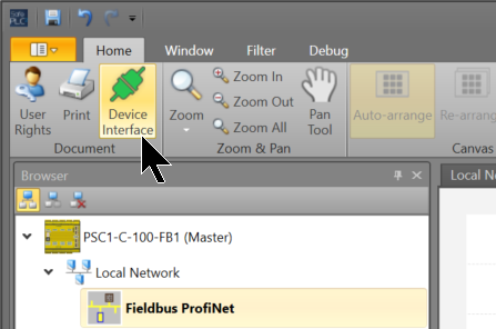
Click SafePLC2>Home>Device Interface.
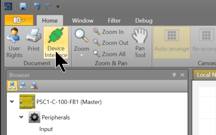
Click SafePLC2>Home>Device Interface.
As you will be using an RS-232 cable, you should set the COM Port to match the Device Manager.
Finally, click the Connect button to connect the CPU and SafePLC2.
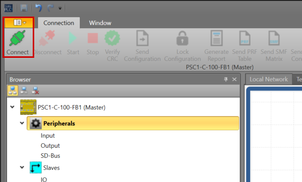
OK to proceed. So I connected the SafePLC2 to the PSC1-C-100-FB1.
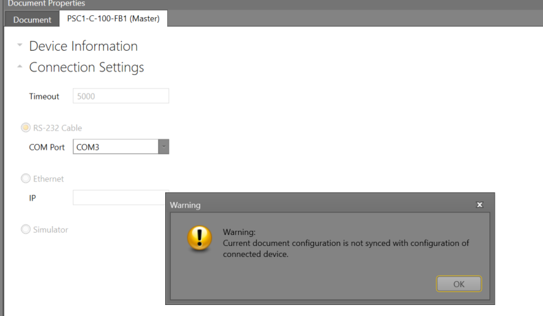
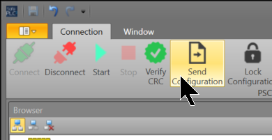
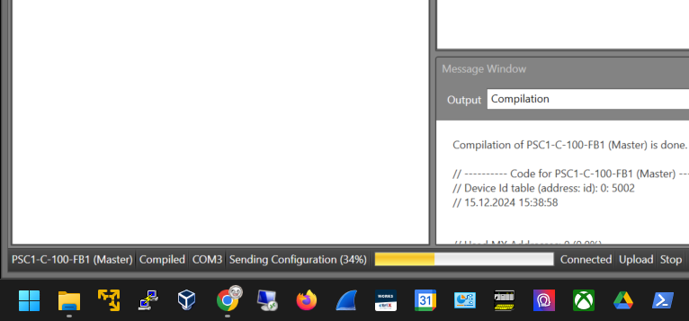
Send Configuration
OK to proceed. So I connected the SafePLC2 to the PSC1-C-100-FB1.
しばらくお待ち下さい…
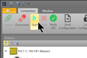
Start
Finally, click the Start button to set the PSC1-C-100-FB1 CPU to RUN MODE.
Monitor
The SafePLC tool also has IO and programme monitoring functions – click on Device Interface.
Click Conenct to connect the PC to the PSC1-C-100-FB1.
Next, click on Diagnostics.
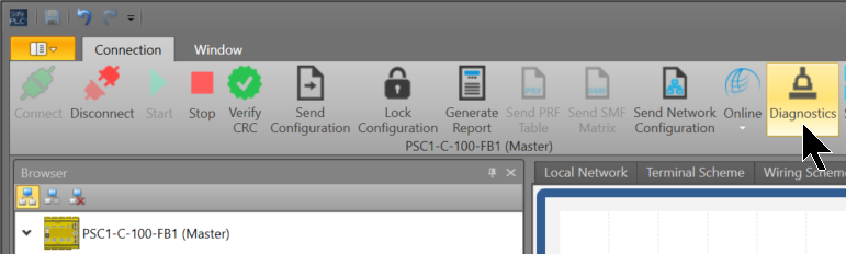
Done!We were able to Monitor the programme we just created.
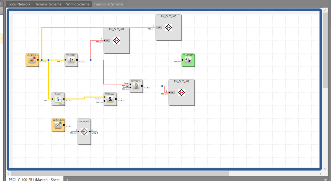
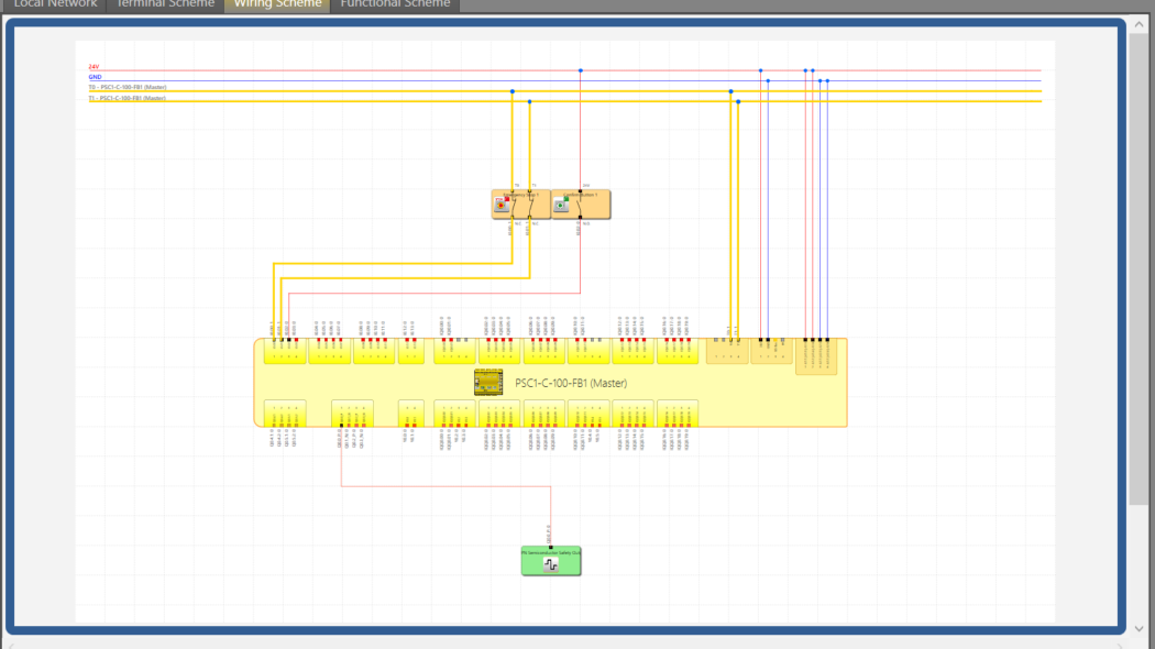
Of course, it is possible to check the status of each IO not only from the programme but also from the wiring diagram (Wiring Scheme).
Codesys Side
The next step is to build the Codesys side. The product used in this article is Berghof’s Codesys Controller.
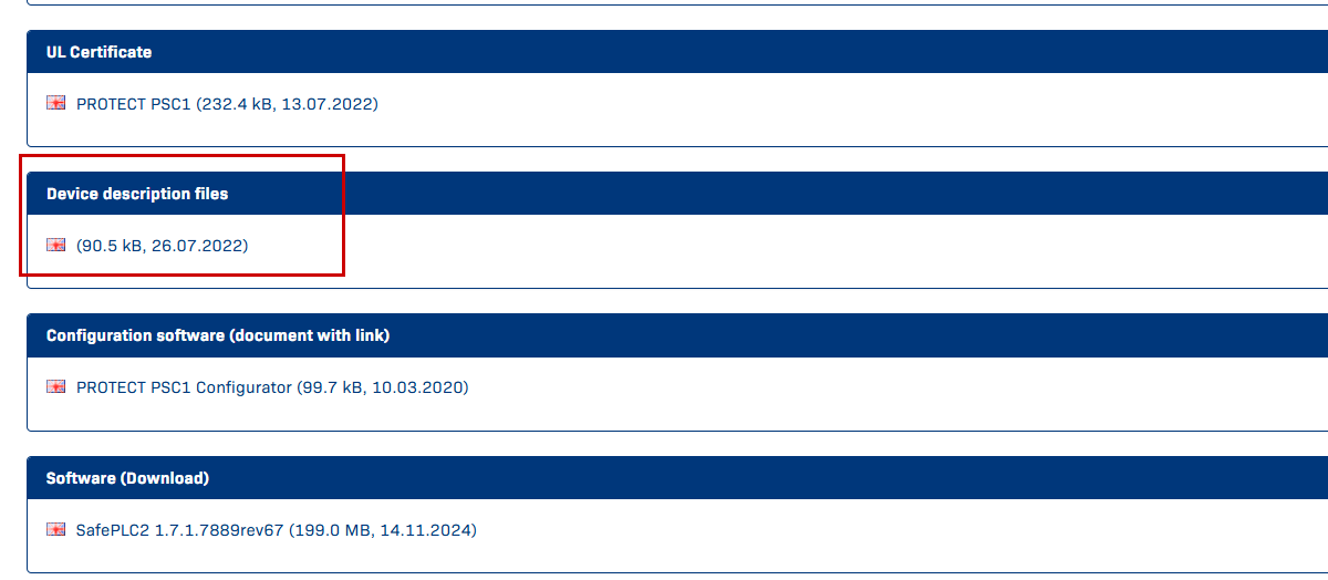
Install GSDML File
To set up a Profinet network, download the GSDML from the Schmersal website.
https://products.schmersal.com/en_IO/psc1-c-100-fb1-103008452.html
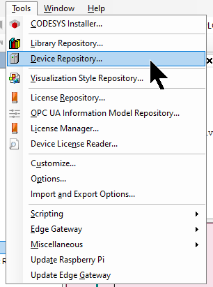
Start the Codesys IDE and click on >Tools>Device Repository.
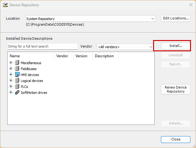
Click Install.
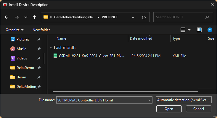
Open the GDSML File downloaded from the SCHMERSAL HP earlier.
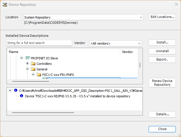
Done!
Add Ethernet Driver
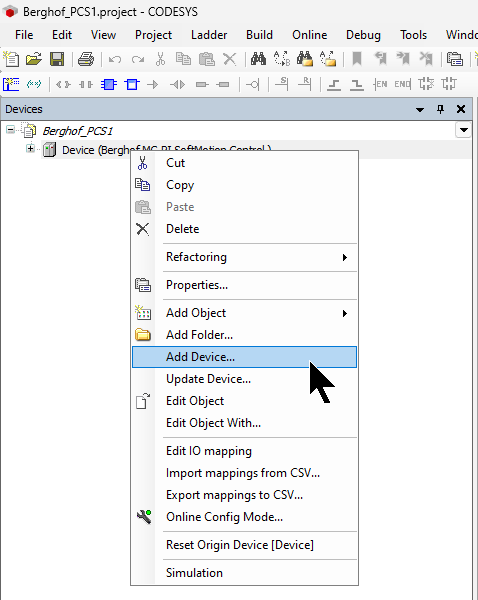
Next, to add an Ethernet Driver to the Codesys project, go to Device>Right click>Add Device.
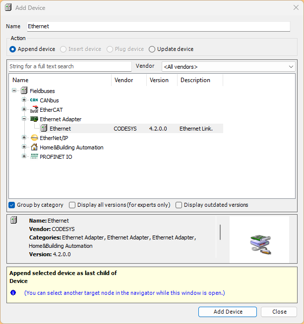
Select Ethernet Adapter>Ethernet and add with Add Device.
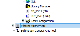
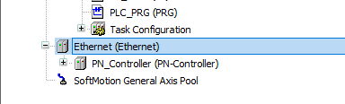
Done!
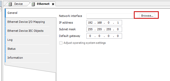
Configure Ethernet Interface
Configure the appropriate Ethernet Adapter under General>Network Interface>Browse.
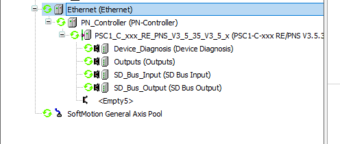
Add Profinet IO Controller
Next, to add a Profinet IO Controller, go to Ethernet>Right click>Add Device.
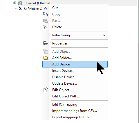
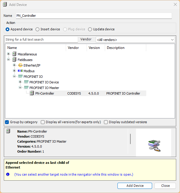
Select PROFINET IO>PROFINET IO Master>PN-Controller and add the Profinet IO Controller in Add Device.
Configure PN Controller
To configure the Profinet Controller, click on the PN Controller you have just added>General.
This is the Profinet IO Controller configuration screen.
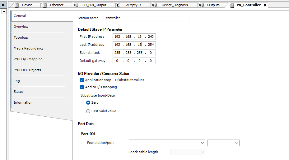
Default Slave IP Parameter
The Default Slave IP Parameter allows you to set the range of IP addresses to be automatically assigned to the Profinet Device to be added under the PN Controller.
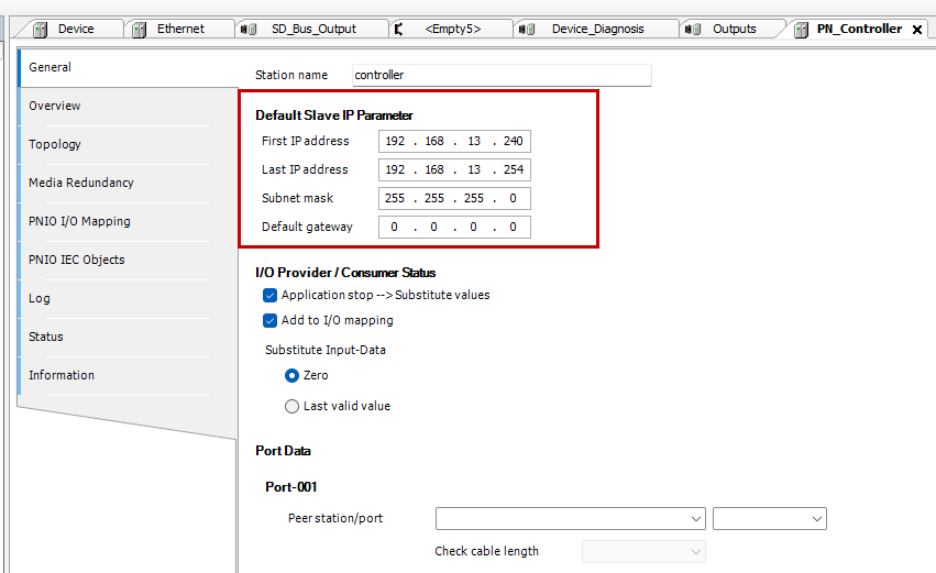
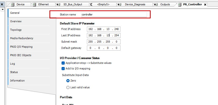
Station Name
This is the name of the PN Controller device.
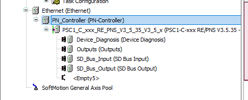
Add Profinet IO Devies
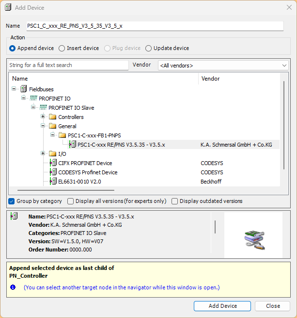
Next, right-click PN Controller>Add Device to add a Profinet IO device.
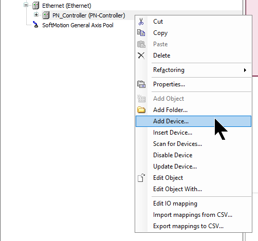
Add PSC1-C-xxx from SCHMERSAL.
Configure Profinet IO Devices
Now configure the Profinet IO device PSC1-C-100-FB1.
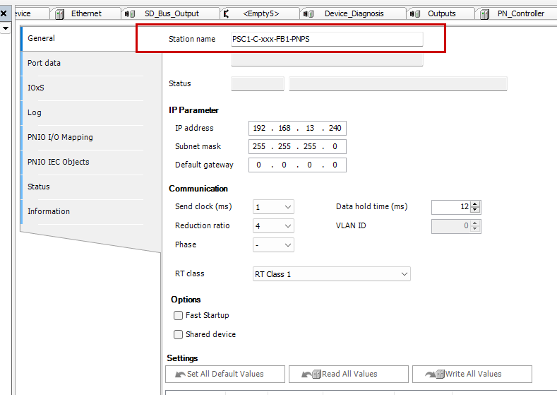
IP Parameter
Set the IP address of PSC1-C-100-FB1 in General>IP Parameter.
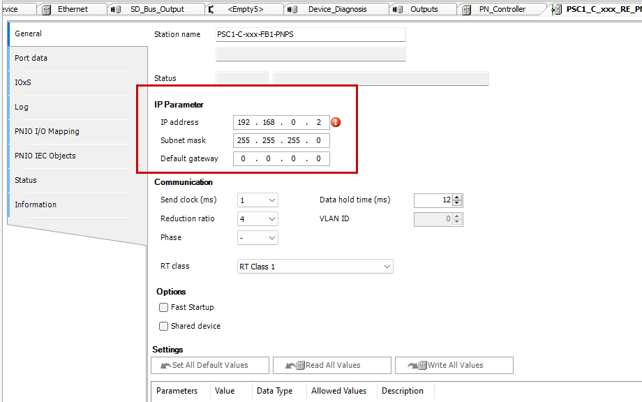
Station Name
Set the device name of the PSC1-C-100-FB1 in Station Name.
Assign Profinet Parameters
You can assign Profinet IP and device names from the SafeyPLC2 tool from Schmersal, but also in the Codesys IDE: click ON Controller>Right click>Scan for Devices.
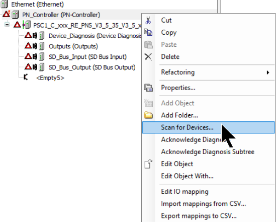
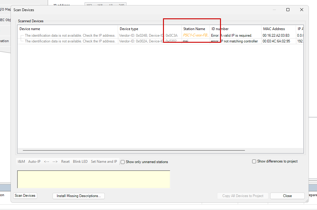
The Profinet device search screen is now displayed.
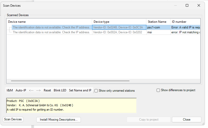
Set the Station Name to match the Profinet Configuration.
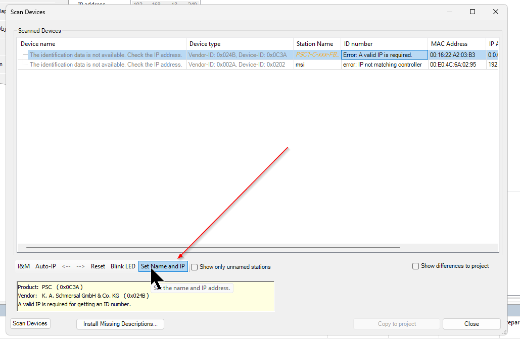
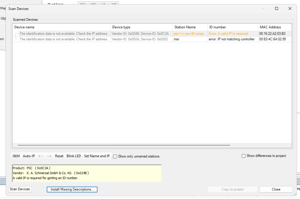
Next, click Set Name and IP and assign the device name and IP to PSC1-C-100-FB1.
Done!
DUT
Create structures in the Codesys programme.
DUT_PSC1_Profile2_InputData
This is the input data for Profile 2 of PSC1-C-100-FB1.
| TYPE DUT_PSC1_Profile2_InputData : STRUCT usiPSC1Mode :USINT; usiAliveCounter :USINT; arrbErrorBytes :ARRAY[0..1]OF BYTE; arrxLogicData :ARRAY[0..407]OF BOOL;//ID END_STRUCT END_TYPE |
DUT_PSC1_Profile2_OutputData
This is the output data for Profile 2 of PSC1-C-100-FB1.
| TYPE DUT_PSC1_Profile2_OutputData : STRUCT arrxLogicData :ARRAY[0..31]OF BOOL;//ID END_STRUCT END_TYPE |
DUT_PSC1_Profile2_IO
This is a structure that summarises the input/output data defined earlier.
| TYPE DUT_PSC1_Profile2_IO : STRUCT in:DUT_PSC1_Profile2_InputData; out:DUT_PSC1_Profile2_OutputData; END_STRUCT END_TYPE |
GVL
Define input and output data in the Global Variables List.
| {attribute ‘qualified_only’} VAR_GLOBAL PSC1:DUT_PSC1_Profile2_IO; _rawIN AT %IB1000:ARRAY[0..127]OF BYTE; _rawOUT AT %QB1000:ARRAY[0..3]OF BYTE; END_VAR |
Program
The next step is to create a programme.
FB_PSC1
This FB handles the inputs and outputs of PSC1-C-100-FB1.
| FUNCTION_BLOCK FB_PSC1 VAR_IN_OUT ioarrayData_IN :ARRAY[*]OF BYTE; ioarrayData_OUT :ARRAY[*]OF BYTE; ioData :DUT_PSC1_Profile2_IO; END_VAR VAR_OUTPUT END_VAR ioData.in.usiPSC1Mode:=ioarrayData_IN[0] AND 16#000F; ioData.in.usiAliveCounter:=ioarrayData_IN[0] AND 16#00E0; ioData.in.arrbErrorBytes[0]:=ioarrayData_IN[3] AND 16#0F; ioData.in.arrbErrorBytes[1]:=ioarrayData_IN[4] AND 16#0F; MEM.MemMove( pSource:=ADR(ioarrayData_IN[5]) ,pDestination:=ADR(ioData.in.arrxLogicData) ,uiNumberOfBytes:=51 ); MEM.MemMove( pSource:=ADR(ioData.out.arrxLogicData) ,pDestination:=ADR(ioarrayData_OUT[0]) ,uiNumberOfBytes:=4 ); |
MAIN
This is the MAIN programme.
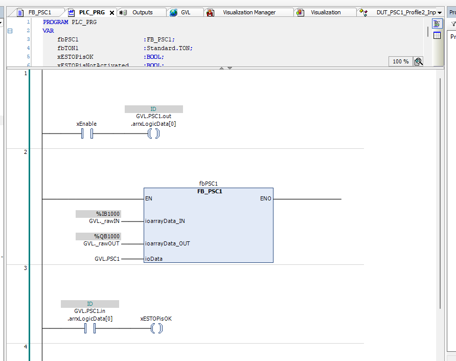
VAR
Here are the variable definitions for the MAIN programme.
| PROGRAM PLC_PRG VAR fbPSC1 :FB_PSC1; fbTON1 :Standard.TON; xESTOPisOK :BOOL; xESTOPisNotActivated :BOOL; xSystemOK :BOOL; xEnable :BOOL; END_VAR VAR CONSTANT cxAlwaysON :BOOL:=TRUE; END_VAR |
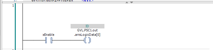
Network1
Network 1 is a valid signal for Codesys to SCHMERSAL PSC1-C-100-FB1.
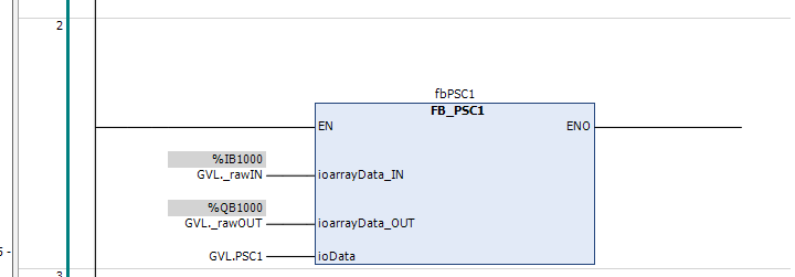
Network2
Network 2 calls the FBs that have just been added.
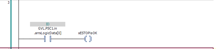
Network3
Network 3 checks whether the emergency stop is normal from the data sent from PSC1-C-100-FB1 to Codesys.
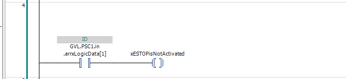
Network4
Network 4 checks whether the emergency stop is disabled from the data sent to PSC1-C-100-FB1 to Codesys.
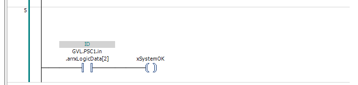
Network5
Network 5 checks whether the status of the entire non-system is OK from the data sent to PSC1-C-100-FB1 to Codesys.
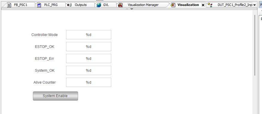
Visuilation
The final step is to create a simple Codesys Visuilation.
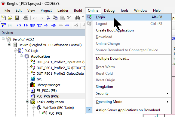
Login
Go to Online>Login and download the project.
Result
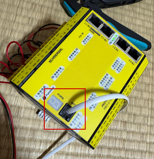
If the PSC1-C-100-FB1 starts up normally, the Status LEC on the PSC1-C-100-FB1 itself will display “4”.
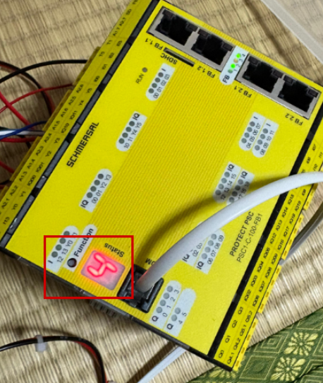
Profinet communication is also normal.
こちらの動画で操作確認をすることができます。