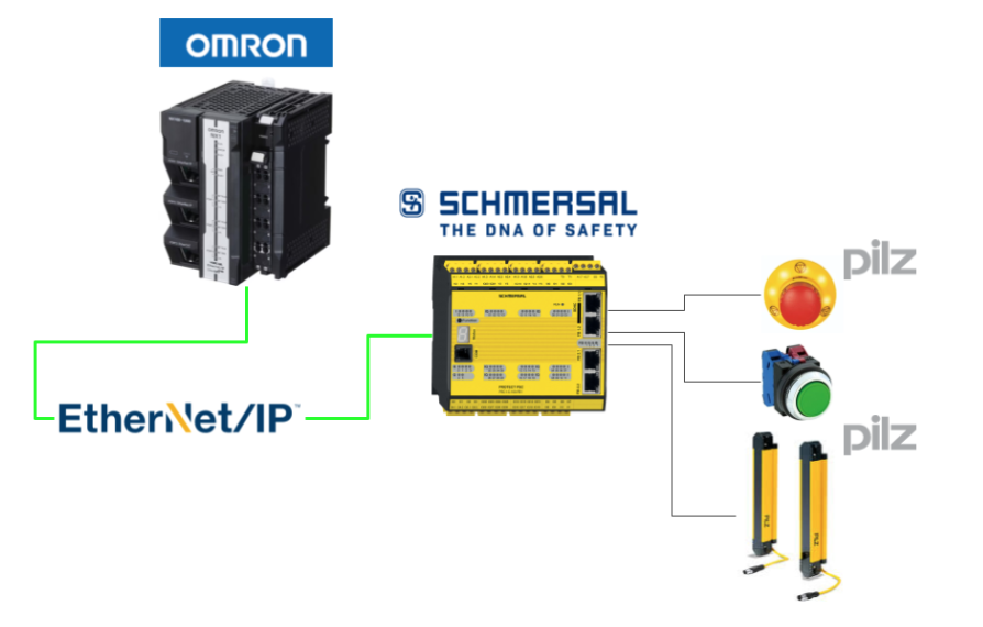
This is a new series, in which various articles will be developed using the PSC1-C-100-FB1 Safety Controller from Schmersal. Episode 5 will build Ethernet/IP communication between the PSC1 Controller and OMRON connected to the Pilz light curtain.
Come on, let’s enjoy FA.

Reference Video
Schmersal.Open box with PSC1-C-100-FB1!
Reference Link
http://soup01.com/en/category/schmersal_en/psc1-en/
Implementation
This is the structure of this article.
Schmersal Side
The Schmersal side is built first.

Configure Fiedbus
PSC-C-100-FB1 Enables Ethernet/IP Fieldbus on the safety controller.

Checkbox under Local Network>Fieldbus.

A Fieldbus entry now appears under Local Network.

The next step is to configure the Fieldbus settings.

Set to Ethernet/IP from the Drop-List of the Network Proptotype.

Done!

The next step is to set up the device Profile that communicates to the Ethernet/IP Fieldbus. In this article we will use Profile1 (Logic data).

The Fieldbus name was also automatically changed to EthernetIP.

Done!

Program
This is the safety programme we have created for the Schmersal PSC-C-100-FB1.

To check that the 408Bit of data between PSC-C-100-FB1 and OMRON NX1 has also been received properly, use the 405th and 407th Fieldbus output Bit at the very back.

The 31st Bit of input data is also the last one.

Connect to the Controller
Connect the COM Port of the PSC1-C-100-FB1 and the dedicated cable to the PC.

Click SafePLC2>Home>Device Interface.

Click Connection Settings.

As you will be using an RS-232 cable, you should set the COM Port to match the Device Manager.

Finally, click the Connect button to connect the CPU and SafePLC2.

OK to proceed. So I connected the SafePLC2 to the PSC1-C-100-FB1.

Send Configuration
Click Send Configuration to transfer your project to PSC1-C-100-FB1.

Please wait a moment…

Assign IP Address
Once the EthernetIP Configuration has been downloaded to the PSC-C-100-FB1, connect the SafePLC2 tool to the PSC-C-100-FB1 and click IP Administrator.

This is the SafePLC2 tool to configure the IP settings of the PSC-C-100-FB1.

Click on EthernetIP Tab>Select the appropriate Ethernet interface>Scan Network to find PSC-C-100-FB1.

Done!PSC-C-100-FB1 found. Select the relevant Safety Controller>Set IP Address>Click Set IP Address Via DHCP.

Done!So I assigned an IP address to PSC-C-100-FB1.

OMRON Side
Now build the Omron side.

Download EDS File
To set up an Ethernet/IP network, download EDS from the Schmersal HP.
https://products.schmersal.com/en_IO/psc1-c-100-fb1-103008452.html

IP Settings
Go to Configurations and Setup>Controller Setup>Build-in Ethernet/IP Port and set the IP address of the same Subnet as PSC-C-100-FB1.

Global Variables
The next step is to define the Global variable.
- DataFromPCS is the data received from the PSC-C-100-FB1 Controller.
- DataToPCS is the data sent from OMORN.

DUT
This is the structure defined in this article.


arr408Bit UNION
This is the same UNION type as 408Bit and 51Byte.
| xData ARRAY[0..407] OF bool bData ARRAY[0..50] OF byte |
arr31Bit UNION
This is the same UNION type as 32Bit and 4Byte.
| xData ARRAY[0..31] OF bool bData ARRAY[0..3] OF byte |
dut_PCS_IN STRUCT
This is a structure that contains the data to be sent from the PSC1-C-100-FB1 to the OMRON NX1 via Ethernet/IP.
| siMode SINT siAliveCounter SINT stLogicData arr408Bit |
dut_PCS_Out STRUCT
This is a structure that contains the data to be sent from OMROn to PSC1-C-100-FB1 via Ethernet/IP.
| stLogicData arr31Bit |
dut_PCS STRUCT
This is a structure that brings together input and output data.
| stin dut_PCS_IN stout dut_PCS_Out |
Function Block
Now, to add a Function Block, go to Function Block>Right-click>Add>Ladder.

Done!A Function Block has been added.

VAR
This is the InOut interface setting of the Function Block.
- ioData is the structure that exchanges data with the PSC-C-100-FB1 Controller defined earlier.
- ioDataFromPCS is the data received from PSC-C-100-FB1 via EthernetIP.
- ioDataToPCS is the data sent to PSC-C-100-FB1 via EthernetIP.

Program
This is the programme part of the Function Block, this time using Inline-ST.
Network1
Network 1 is a programme that divides the received data from the PSC-C-100-FB1 into Mode, LiveCounter and Logic Data.
| ioData.stin.siMode:= BYTE_TO_SINT( ioDataFromPCS[0] AND 16#0F); ioData.stin.siAliveCounter:= BYTE_TO_SINT(ioDataFromPCS[0] AND 16#E0); FOR _iCounter:=0 TO 50 DO ioData.stin.stLogicData.bData[_iCounter]:= ioDataFromPCS[_iCounter+5]; END_FOR; |
Network2
Network 2 is a programme that outputs Logic Data to be sent to PSC-C-100-FB1.
| FOR _iCounter:=0 TO 3 DO ioDataToPCS[_iCounter]:= ioData.stout.stLogicData.bData[_iCounter]; END_FOR; |
MAIN
This is the MAIN programme. Call the FB you have just created and assign the appropriate parameters.

| stPCS.stout.stLogicData.xData[31]:=xReset; _FB_PSC( stPCS ,DataFromPCS ,DataToPCS ); ; xReady:=stPCS.stin.stLogicData.xData[0]; xESTOP:=stPCS.stin.stLogicData.xData[405]; xLightGurtain:=stPCS.stin.stLogicData.xData[407]; |
Ethernet/IP Configurations
The next step is to configure the Ethernet/IP connection settings.

Port1 was used in this article, so right-click Port1>Edit.

This is the Ethernet/IP connection screen.

Register variables
Click Registration All to register the Global variables defined in the project.

Register the Global variables you declared earlier.

Done!

Install EDS File
Next, click on Display EDS Library to install the EDS File.

Click Install.

Select the EDS File downloaded from Schmersal HP.

Done!PSC-C-100-FB1 installed in Schmersal.

Add new Ethernet/IP Adapter
Next, click on the + button to add the PSC-C-100-FB1 to the Ethernet/IP network.


Node Address
The Node Address is the IP address of the PSC-C-100-FB1.

Model Name
Model name selects the PSC-C-100-FB1 safety controller from Schmersal.


Revision
Revision is only 1.

Add
Click the Add button to add the PSC-C-100-FB1.

Done!

Add Devices to Network
Add the Schmersal PSC-C-100-FB1 added earlier to the Ethernet/IP network.

Done!

Configure the Ethernet/IP settings as shown in the diagram below.
- Input=101, 192Bytes
- Ouput=100, 68Bytes

Online
The last step is to Download the project Online.

Download
Click To Controller to transfer the project to the CPU.

Proceed with Execute.

Done!

Transfer Ethernet/IP Setting
Next, transfer the Ethernet/IP configuration to the CPU.

Proceed with Yes.

Compare the Configuration
Finally, the Compare function is used to CHECK whether the Ethernet/IP settings match those of NX1.

Done!

Result
Check the Ethernet/IP connection status of Port 1.

Done!OMRON NX1 and Schmersal PSC-C-100-FB1 have Ethernet/IP connectivity.


You can check the operation in this video.
OMRON.Communicate with Schmersal PSC Controller via EthernetIP