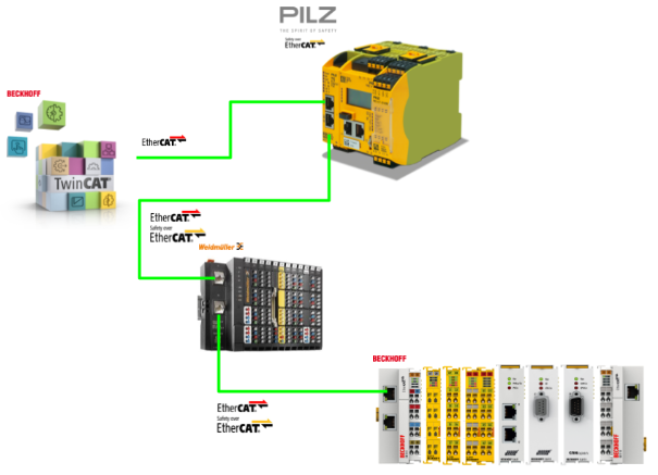
In this article we will use the latest PNOZ communication module EtherCAT FSoE from Pilz to set up an FSoE Master ,and establish FSoE and non-safe EtherCAT communication with the FSoE Slave from Weidmullder and Bechoff.
Let’s get started!
Thanks!
The Device used in this article was loaned to us by PILZ JAPAN.
PILZ
PILZ supports factory automation sites as a total solution supplier with solutions for safety and automation technology, guaranteeing the safety of people as well as machines and the environment, and how safely machines and equipment can be operated. Pilz has 42 subsidiaries and branch offices worldwide and is active in various fields such as packaging, automotive industry, robotic applications, as well as wind power and railroad technology.

Office:
ピルツジャパン株式会社
〒222-0033
横浜市港北区新横浜3-17-5
いちご新横浜ビル 4階
HP
Reference Link
Reference Video
Pilz.PNOZ m EF EtherCAT FSoE Introduction
Pilz.Startup FSOE Master with PNOZ m EF EtherCAT FSoE (with TwinCAT3)
FSoE?
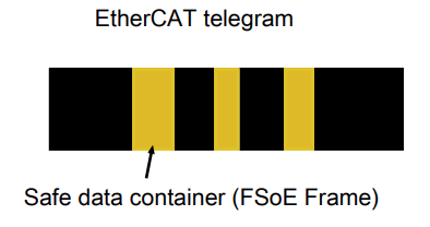
An EtherCAT Network consists of an EtherCAT master and one or more slaves. The EtherCAT Telegram contains standard data and can also transfer safety data (FSoE data).
And the PNOZ m EF EtherCAT FSoE used in this article can be used as FSoE master and FSoE slave. This is because PNOZ m EF EtherCAT FSoE can send and receive non-safety and non-safety related data via EtherCAT via FSoE.
FSoE Log is standardized in the international standard IEC 61784-3 and is a secure communication system for transferring secure process data between FSoE modules.
For FSoE communication via the EtherCAT network, it is a prerequisite that the EtherCAT network is functioning at the EtherCAT master and that the FSoE data is transmitted in a secure data container (FSoE Frame) in the standard EtherCAT telegram.
The FSoE master initiates communication with a Request telegram; the FSoE master receives FSoE data from the FSoE slave and performs safety-related evaluation. Those safety data can be used in the PNOZmulti module program.
It is important to note that the FSoE cycle time for PNOZ m EF EtherCAT FSoE is up to 10 ms.The FSoE Connection is monitored using Watchdog to detect communication interruptions.
PNOZ m EF EtherCAT FSoE?
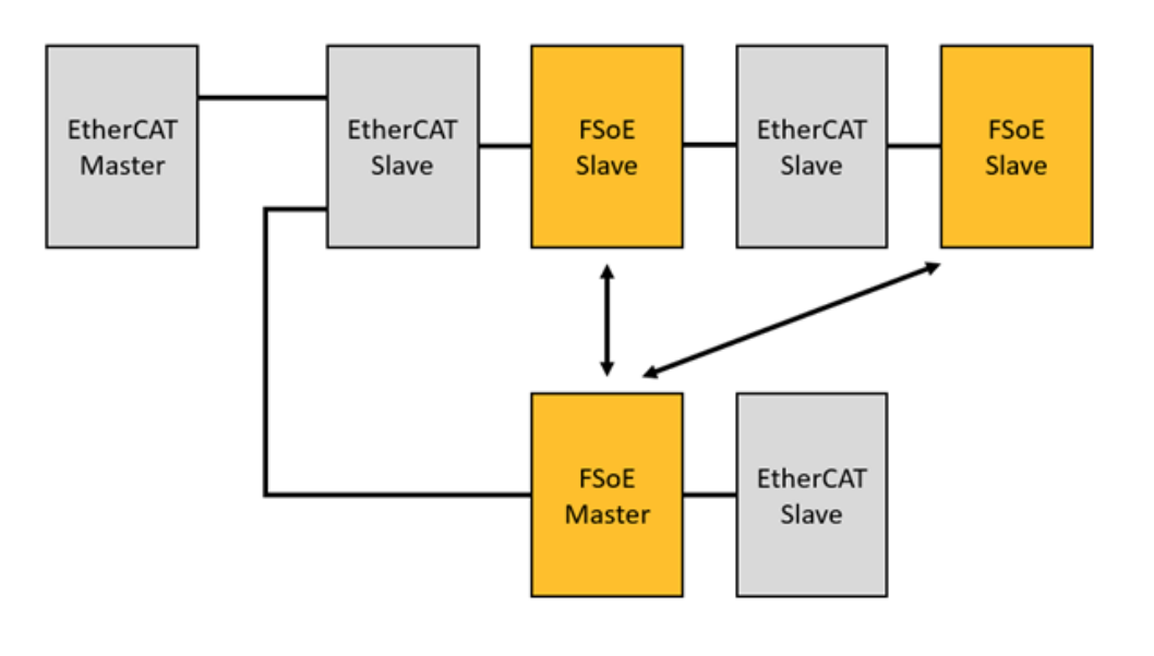
An EtherCAT network requires an EtherCAT master, which communicates with EtherCAT slaves; if Fail-Safe Data are exchanged via FSoE, an FSoE master (e.g. module PNOZ m EF EtherCAT FSoE) and at least one FSoE slave are required. At least one FSoE slave is required.
It is important to note that in an EtherCAT network ,the FSoE master is also one of the EtherCAT slaves. The PNOZ m EF EtherCAT FSoE used in this article can be configured as FSoE master or FSoE slave.
All data from the EtherCAT slaves are transferred via the EtherCAT master; the connection to the FSoE slave must be created in the PNOZmulti Configurator so that the corresponding data from the FSoE slave is available in the FSoE master. The data must be copied or mapped to the EtherCAT master.
PNOZmulti can also operate as a master or a slave, or as a master and a slave simultaneously.
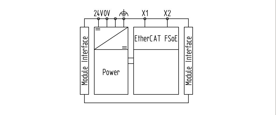
Note that if the connection is lost, the system will automatically reboot. There is no restart interlock. The connection to EtherCAT is then established via two RJ45 sockets; LEDs indicate the status of the expansion modules on the EtherCAT FSoE.
Layout
The base unit and the expansion module PNOZ m EF EtherCAT FSoE are connected via jumpers. The expansion module PNOZ m EF EtherCAT FSoE is automatically configured and started up as soon as the supply voltage is applied or the PNOZmulti control system is reset.
Unit features
This product has the following features;
- Configurable via PNOZmulti Configurator
- Operates as FSoE master: max. 60 connections
- Operates as FSoE slave: max. 4 connections
- Up to 16 bytes input data and 16 bytes output data per connection
- 512 Bit Failsafe input process data and 512 Bit Failsafe output process data can be transferred per FSoE master
- PNOZmulti Configurator allows to define 128 virtual inputs and outputs of PNOZmulti for communication with EtherCAT
- Network protocols: EtherCAT, FSoE
- Status LEDs for communication with EtherCAT and FSoE and for errors
- Up to 1 PNOZ m EF EtherCAT FSoE can be connected to the base unit
Network planning
Before the network is configured and installed, let’s build the FSoE Network.
- Selecting an EtherCAT Master for use in a network
- Selecting an FSoE Master for use in a network
- Select FSoE Slaves for your network
- Structuring the FSoE network
- EtherCAT cycle time (corresponding to the slowest module in the network)
- Define FSoE safety parameters
- FSoE address
- Assign a unique FSoE address in each FSoE device
- Connection ID
- Each FSoE device is assigned a unique Connection ID
- Watchdog timeout [ms]
- The data transfer of the connection is monitored using the Watchdog Timer. Each FSOE device monitors that its communication partner sends a new FSoE frame within the Watchdog Timeout; an appropriate value should also be assigned to each Connection at the Watchdog Timeout location.
- FSoE address
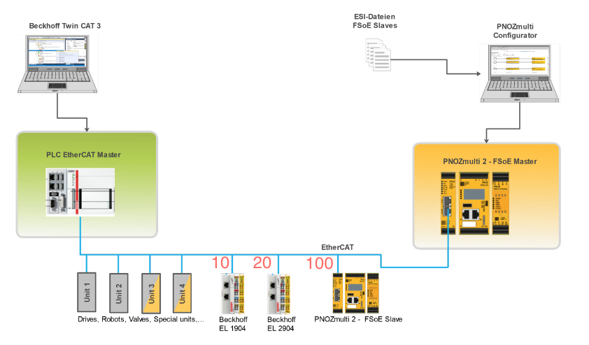
EtherCAT and FSoE application example
Now let’s take a look at how to actually plan and set up an FSoE application.
In this example, a factory with four FSoE devices is planned.
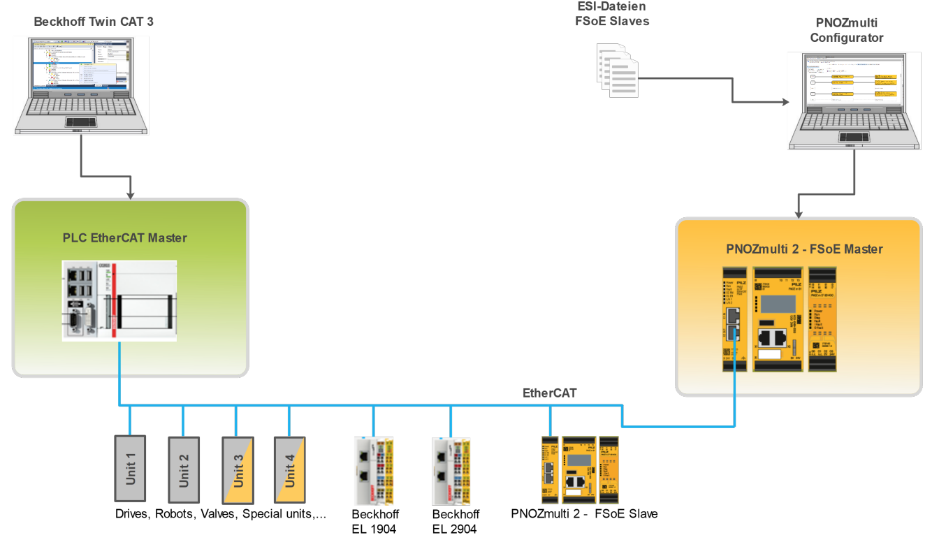
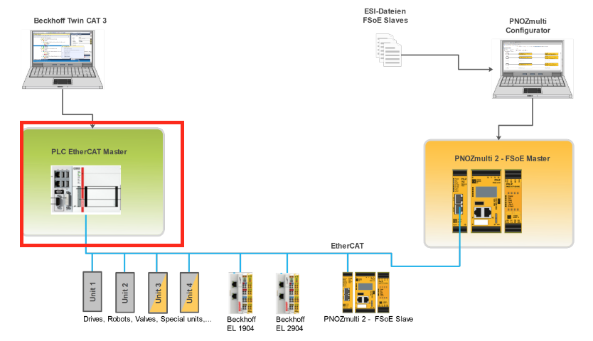
EtherCAT Master?
Beckhoff TwinCAT 3 Runtime is configurated as EtherCAT Master.
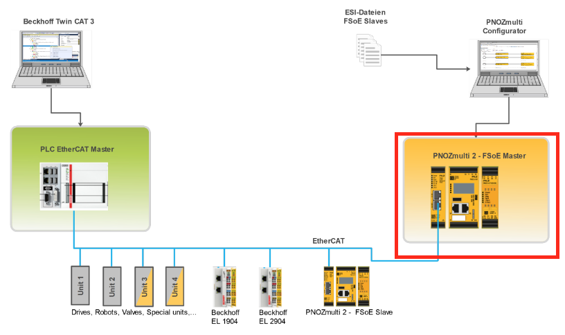
FSoE Master?
PNOZmulti 2 FSoE Master is configured as FSoE Master.
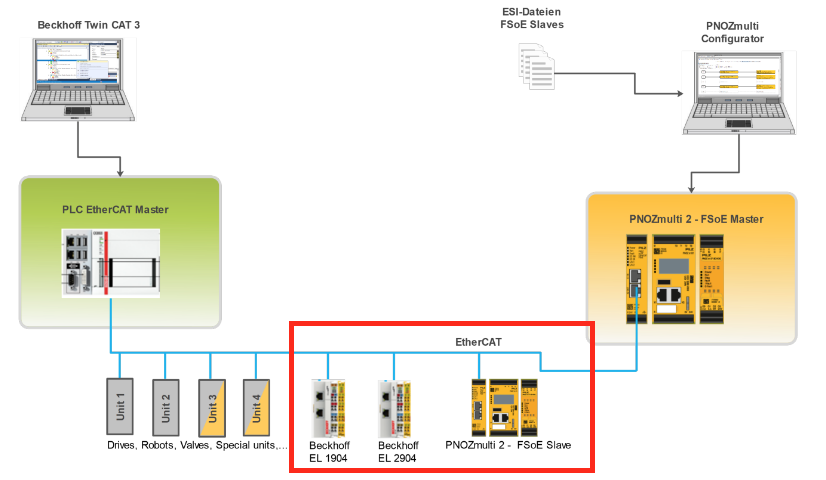
FSoE Slave?
この例で使用するFSoE Slaveは3つあります。下図の赤枠に示しています。
- PNOZmulti 2 – FSoE Slave
- Input module Beckhoff EL1904 – FSoE Slave
- Output module Beckhoff EL2904 – FSoE Slave
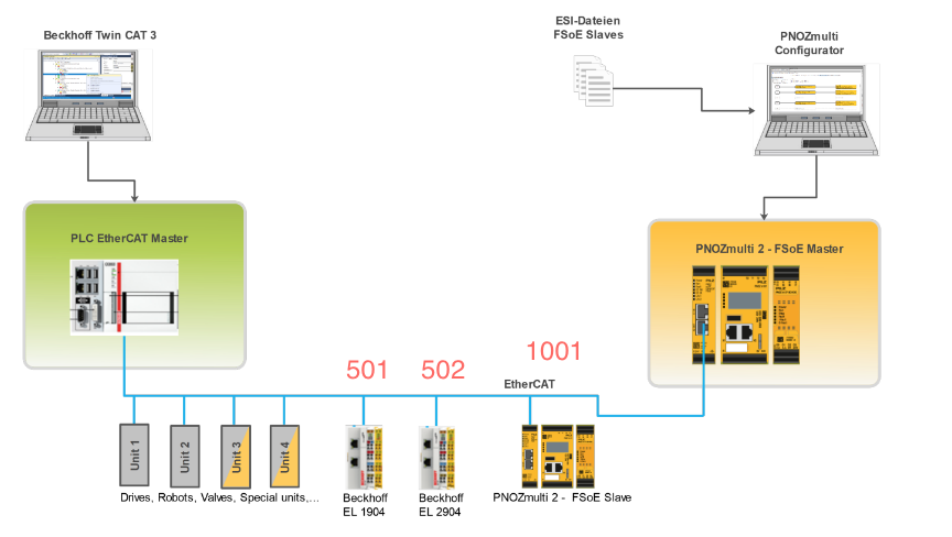
Network Parameters?
Next, let’s set the parameters for the FSoE network.
FSoE Address
Set the FSoE address of each Slave so that they are not covered.
Connection ID
Connection IDs should be set so that they are not covered as well.
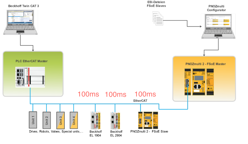
Watch Dog Timer
Watch Dog Timeout time should be set according to the application.
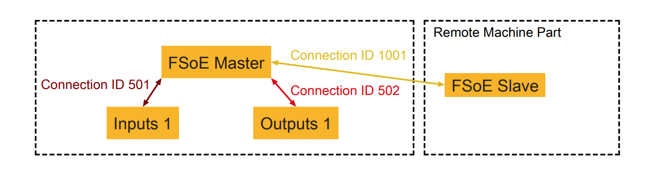
Result
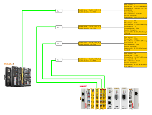
As shown in the figure below, FSoE Master can access FSoE Slave in different areas.
Reaction times
The maximum EtherCAT FSoE reaction time depends on the delay time of the involved components including communication.
The following times must be considered computationally.
- EtherCAT Cycle Time
- PNOZ m EF EtherCAT FSoE Delay Time
- FSoE Slave delay time
- FSoE Master watchdog time
It is important to note that the reaction time of FSoE is affected by changes in EtherCAT cycle time.
Implemetation
Pilz Side
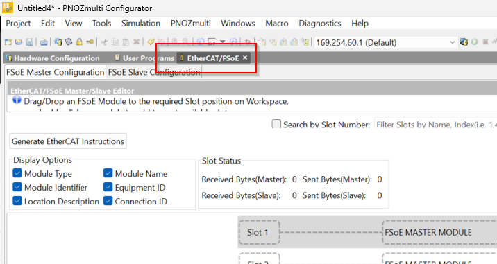
FSoE Configuration
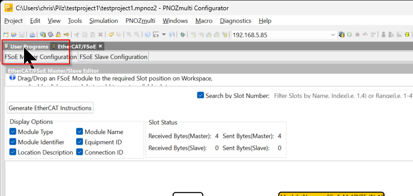
Open the EtherCAT/FSoE Tab from the PNOZmulti Configurator.
Import ESI File
Click on “Import ESI Files” in the EtherCAT/FSoE Slave Library on the right to add an ESI file.
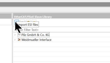
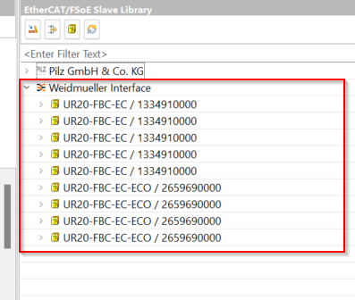
Import the Beckhoff and weidmüller ESI File.
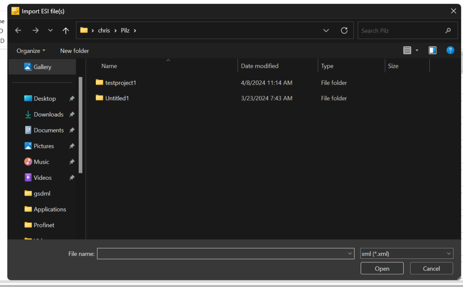
Done!
Configure ESI Connection
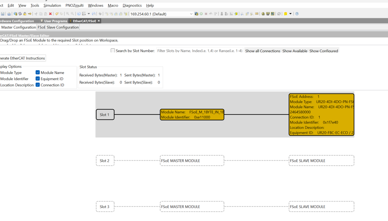
Add Slave in FSOE network from Library to Slot.
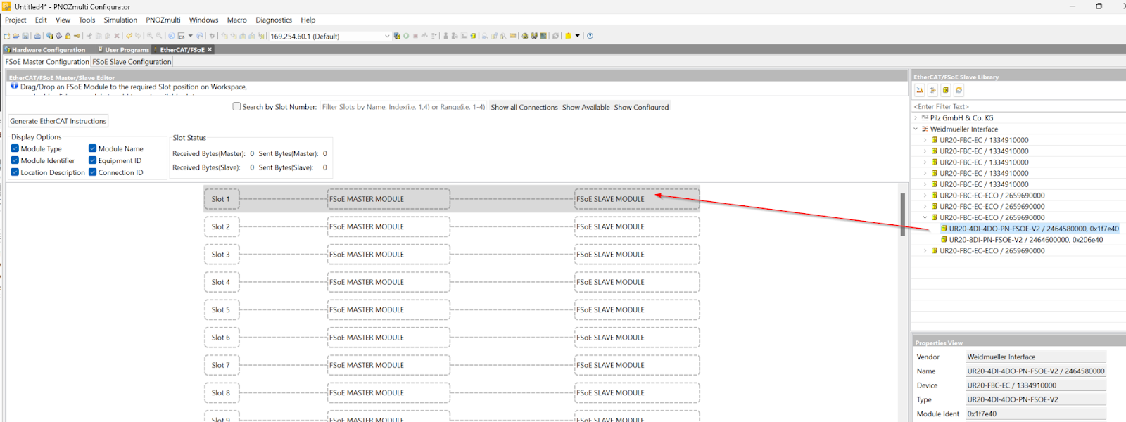
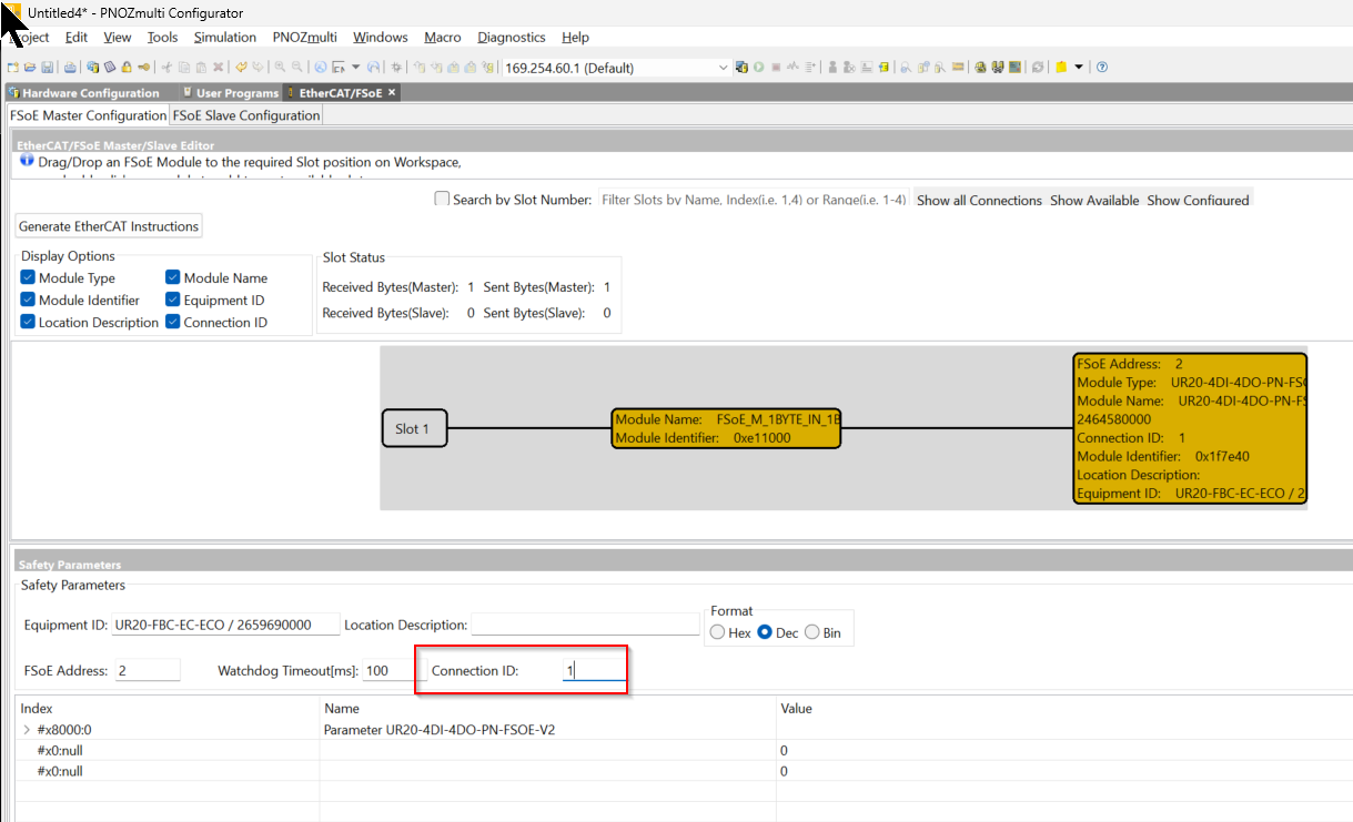
Done!Weidmüller’s UR20-4DI-4DO-PN-FSOE-V2 Slave has been added to Slot 1.
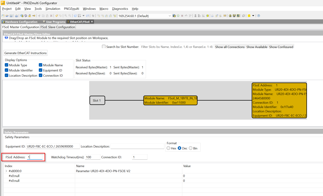
FSoE Address
The FSoE Address should be set according to the DIP switch on weidmüller’s UR20-4DI-4DO-PN-FSOE-V2.

Watchdog Time
Watchdog Time should be set according to the application.
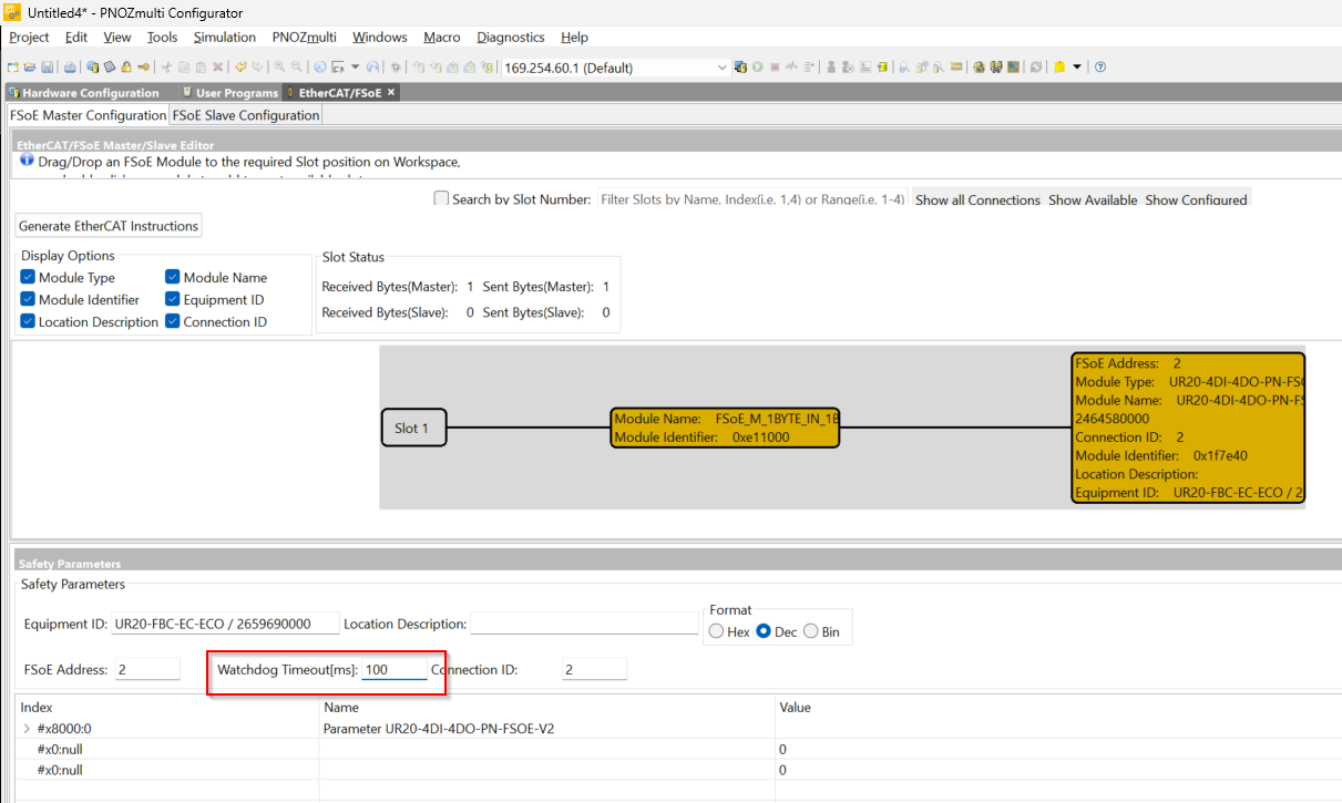
Connection ID
The Connection ID should be set to an ID that is unique within the network.
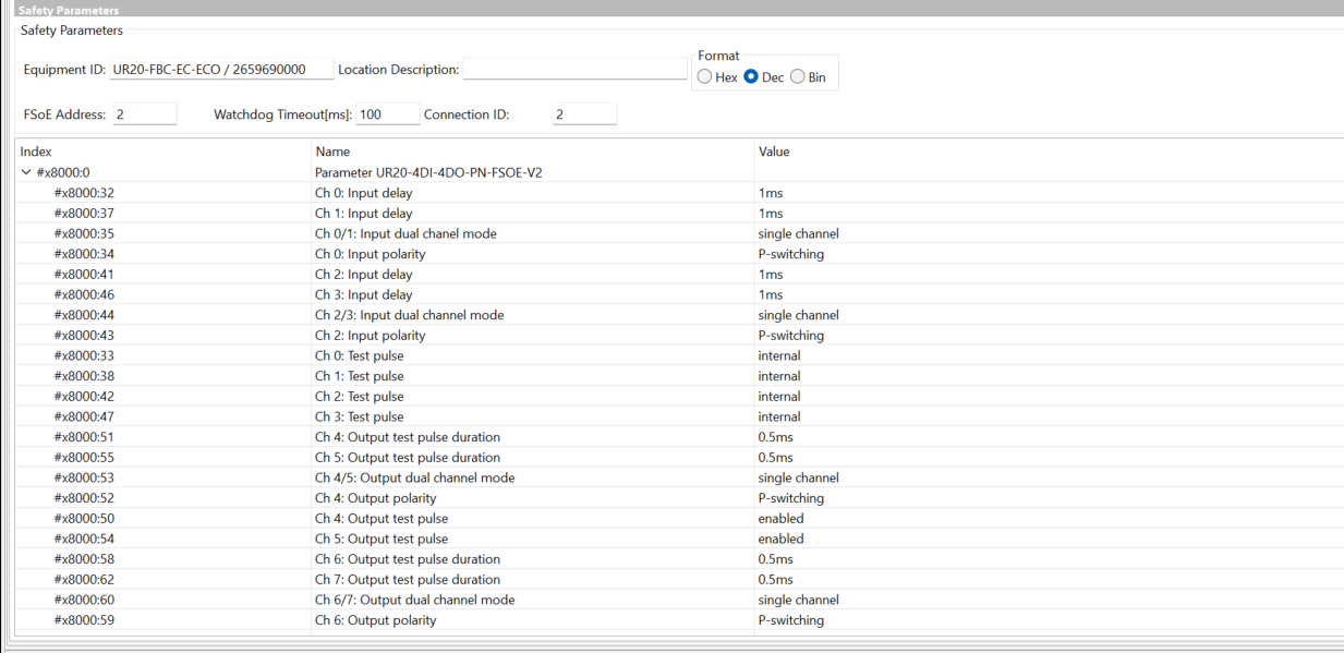
Safety Parameters
The parameters that can be set vary depending on the FSoE Slave.
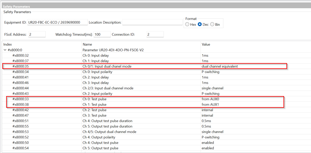
This time we will use 1-to-2 emergency stop inputs and use Test Input on AUX0 and AUX1.
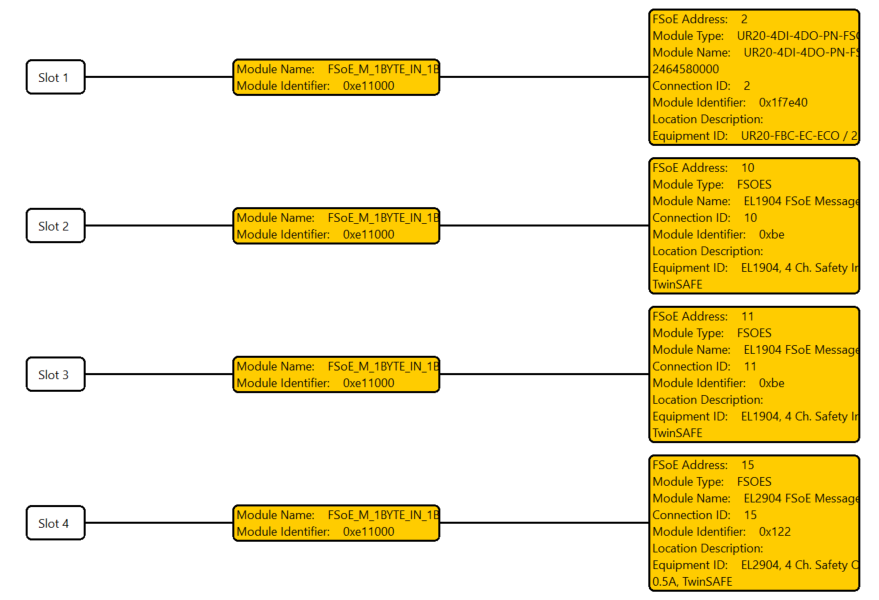
Result
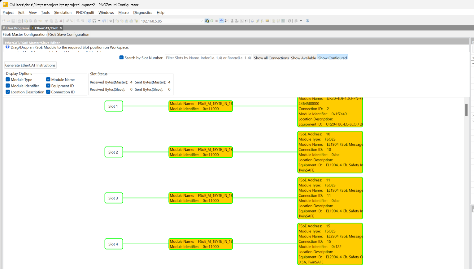
This is the FSoE Configuration for this time.
- Slot1‐weidmüller UR20-4DI-4DO-PN-FSOE-V2
- FSOE Address=2
- Connection ID=2
- Slot2-EL1904
- FSOE Address=10
- Connection ID=10
- Slot3-EL1904
- FSOE Address=11
- Connection ID=11
- Slo4-EL2904
- FSOE Address=15
- Connection ID=15
User Program
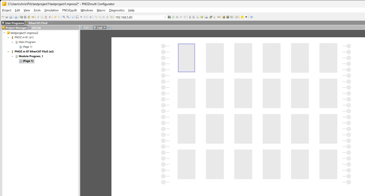
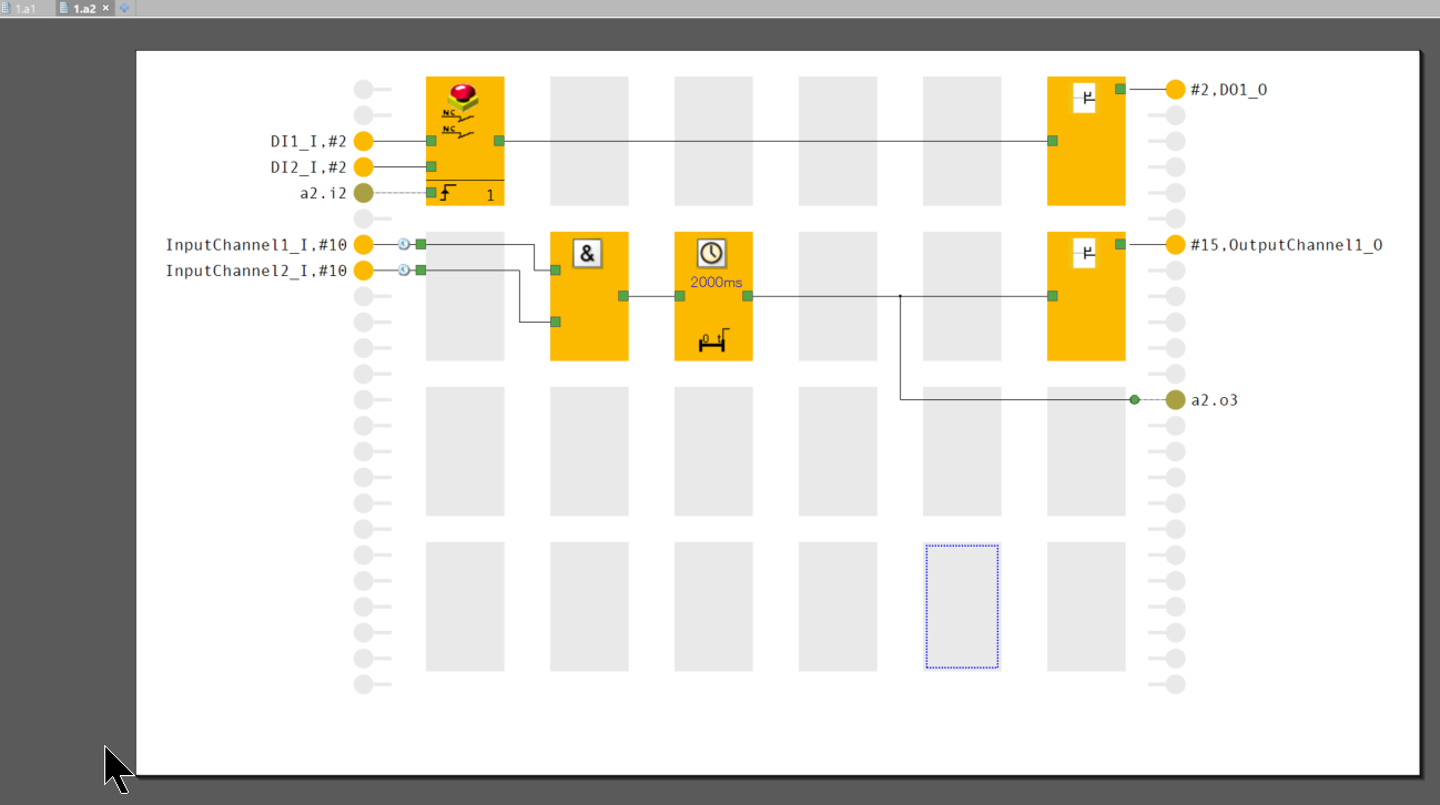
Next, open the User Program Tab to build the safety program.
This is the program building screen of PNOZ 2. Open the EtherCAT FSOE program sheet.
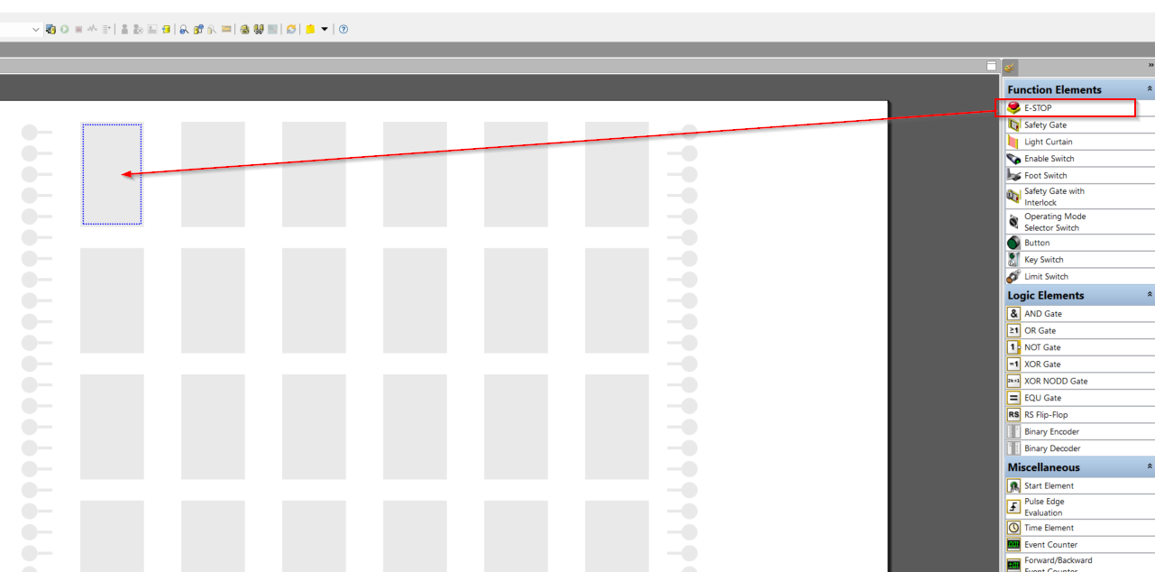
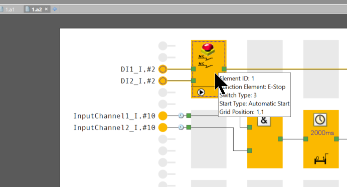
Insert ESTOP Block
Add an ESTOP Block from Function Elements on the right.
The E-STOP Block setting screen appears.
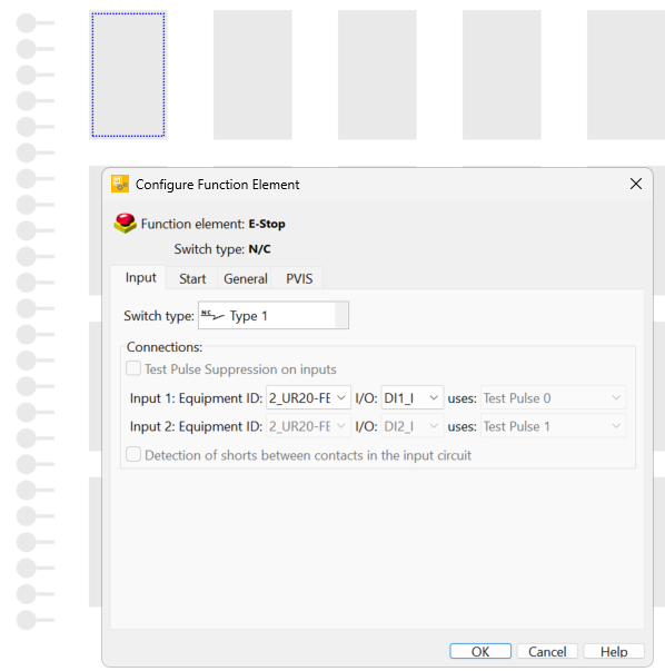
Switch Type
There is a Drop-List in the Switch Type, which is set according to the application and wiring.
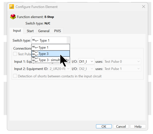
In this article, we will set the ratio at 1:2.
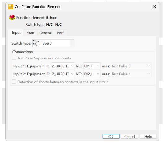
Connections
Connections sets the input signal to be used in the E-STOP Block. Since the Switch Type was set to Type 3 earlier, Input1/Input2 will be displayed and can be set to two input signals.
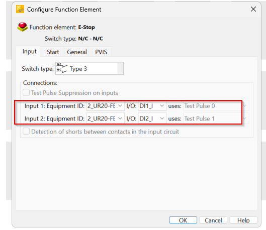
Set it up according to your actual application. In this article, we will use inputs 1 and 2 of UR20-4DI-4DO-PN-FSOE-V2.

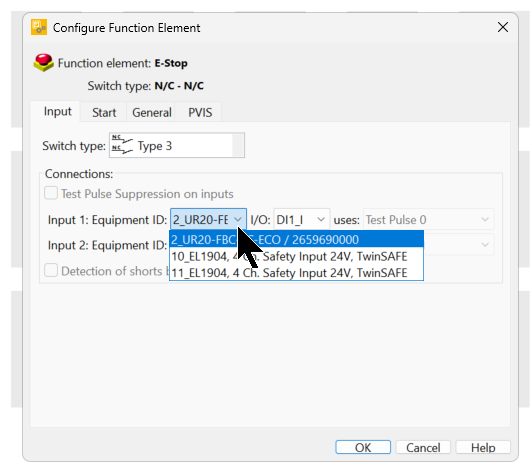
Input1 Equipment ID
The Equipment ID can be set to the corresponding input and the module to be connected.
In this case, set it to UR20-4DI-4DO-PN-FSOE-V2.
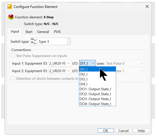
Input1 I/O
I/O can be set to the input Point of the corresponding module.
In this case, set it to DI1_I.
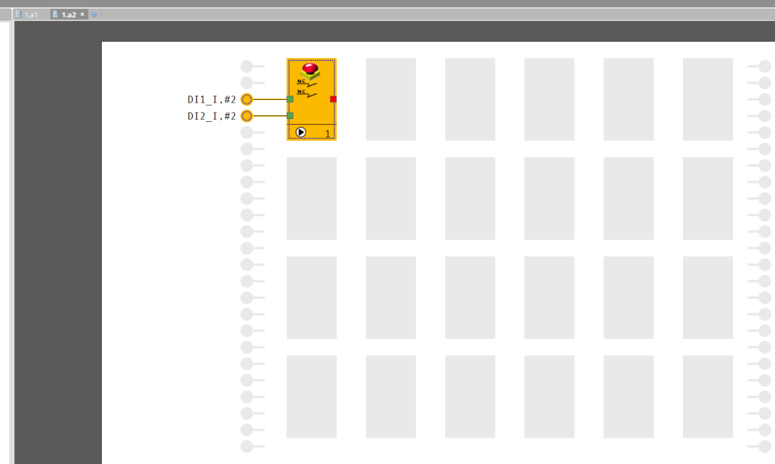
Result
Done!E-STOP Function Element has been added.
Insert Semiconductor Output
Next, let’s add semiconductor output to the sheet.
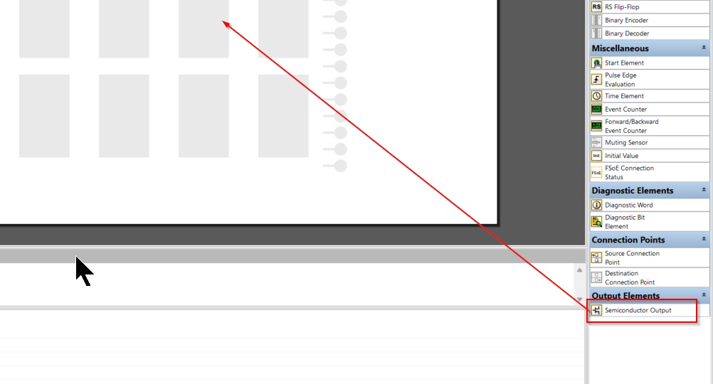
The semiconductor output Function Element setting screen is displayed.
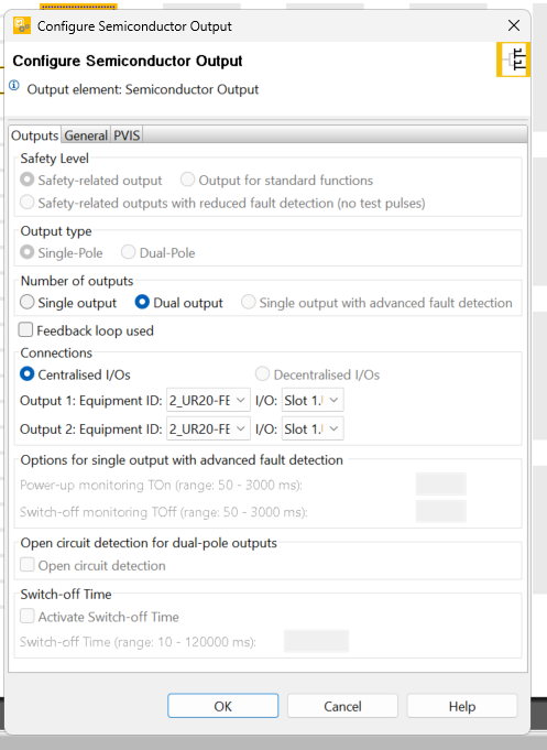
Number of outputs
Set Number of outputs to “Single output” and change the number of outputs to 1.
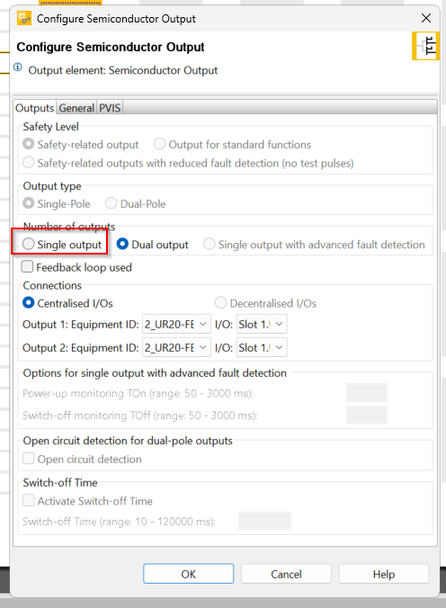
Done!

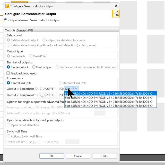
Connections
The next step is to configure the output settings for the relevant Block.
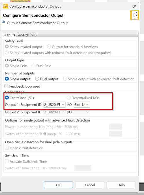
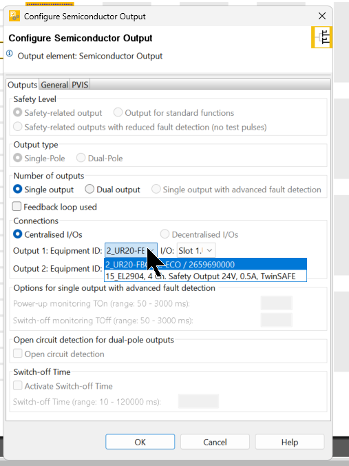
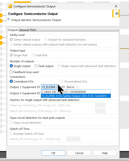
Output1 :Equipment ID
The Equipment ID can be set to the corresponding output and the module to be connected.
In this case, set it to UR20-4DI-4DO-PN-FSOE-V2.
Output2 :I/O
I/O can be set to the input Point of the corresponding module.
In this case, set it to DO1_O.
Result
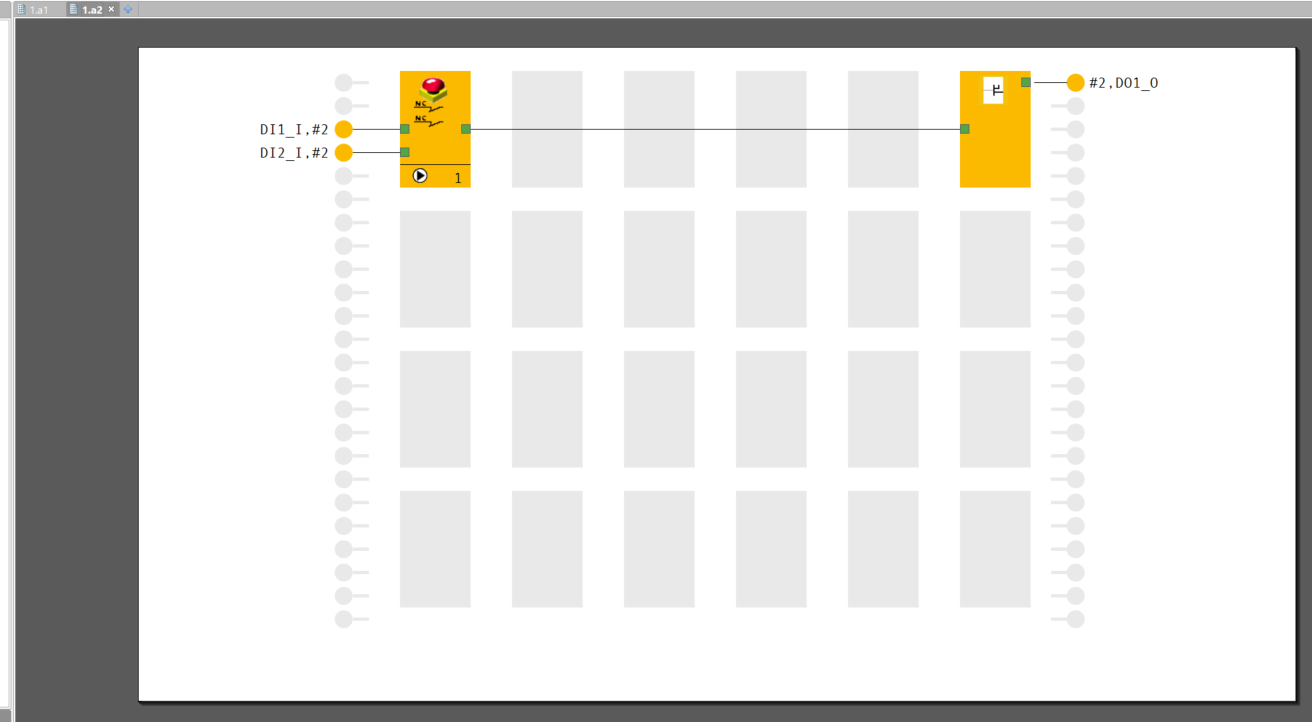
Done!
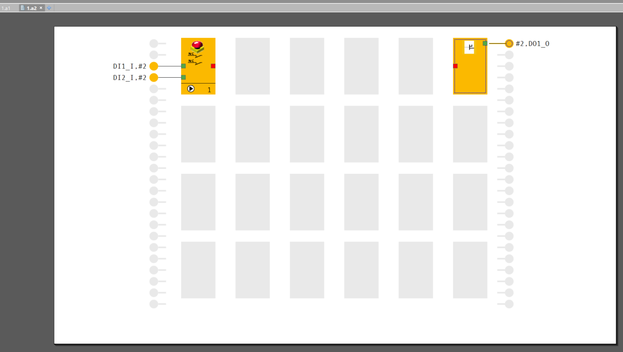
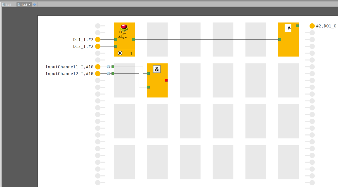
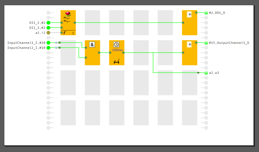
Finally, let’s connect the output of the ESTOP Function Element with the input of the Semiconductor Output.

Done!This allows the output to be controlled On/Off depending on the state of ESTOP.
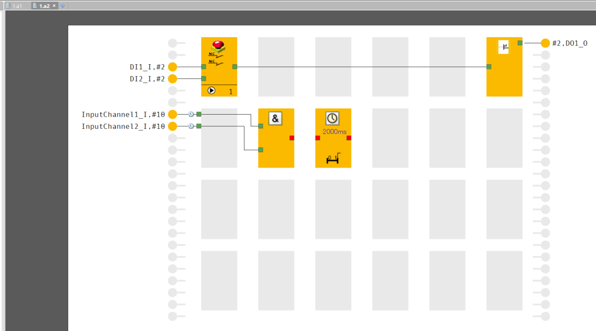
Delay ON Program
Now we will make a simple program that puts Timer as input, delays it for 2s, and then outputs it.
Activate Input
Double-click an unused input point on the Function Sheet.
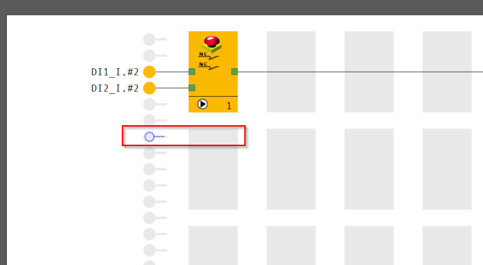
The screen for setting Points to be used for Function Sheets is displayed.
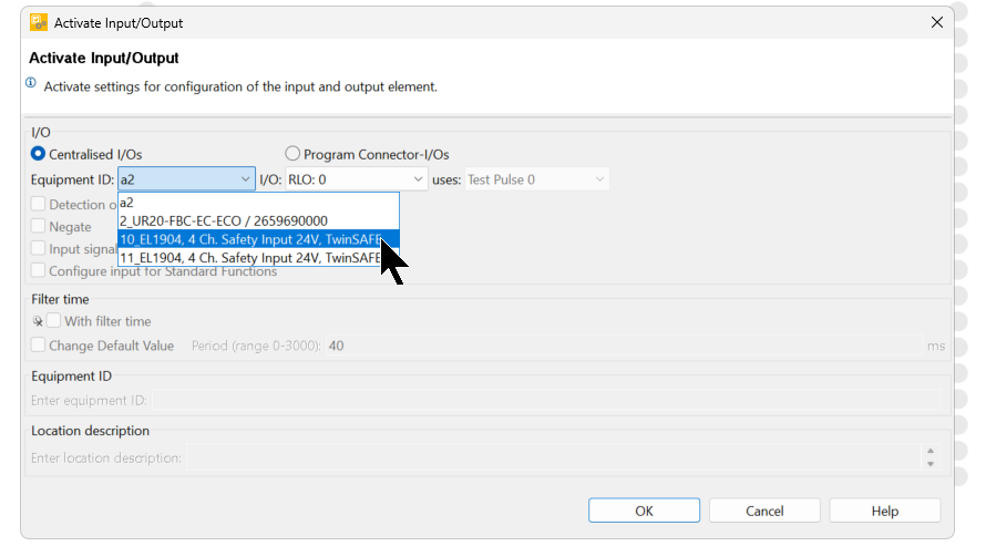
Centrailsed I/O Configration
Here you can set whether to use variables from Function Sheet or data from other modules.
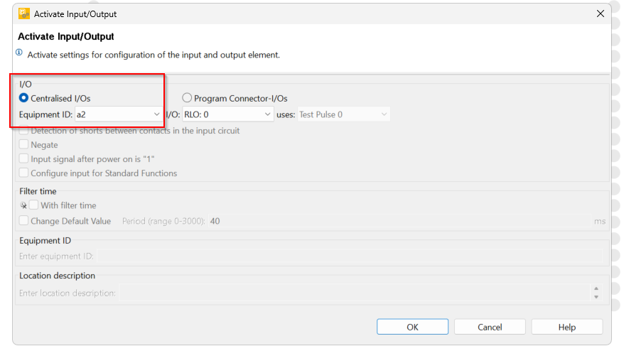
In this case, we will use Beckhoff’s EL1904 with FSoE Address=10.
Done!

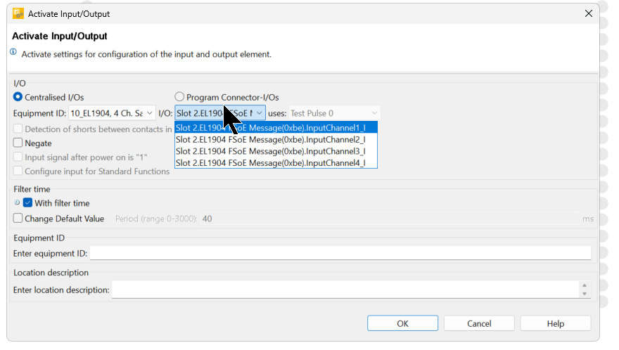
I/O
I/O can be set to the input Point of the corresponding module.
In this case, we will set it to Channel 1 of EL1904.
Add AND Gate Block
Next, add AND Gate to Logic Elements.
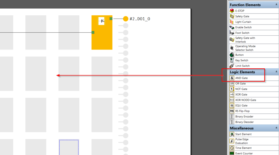
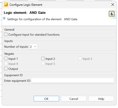
This is the AND Gate settings screen.
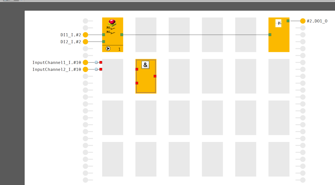
Done!AND Gate has been added.
Connect Inputs->AND Block
Let’s connect the two inputs we just added with the AND GATE input.
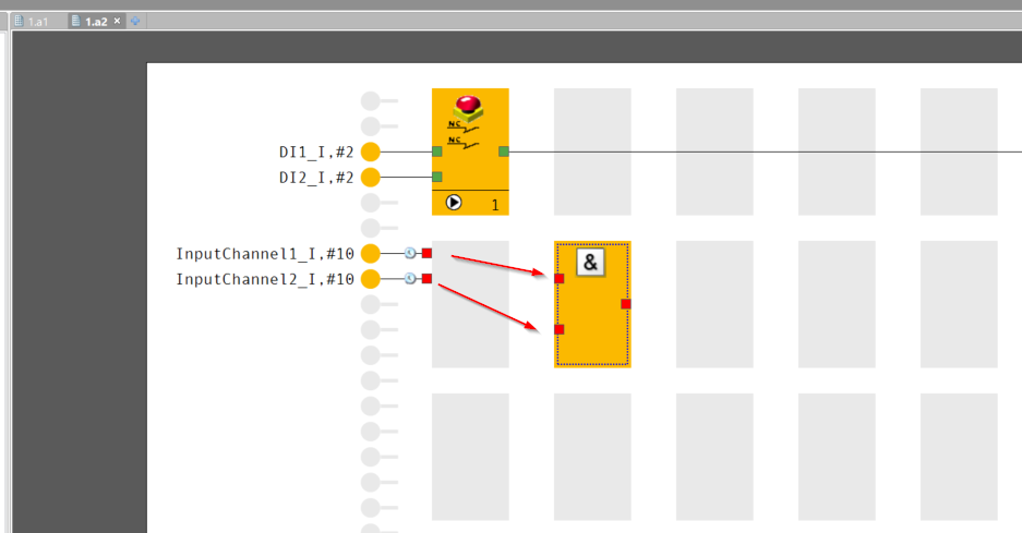
Done!
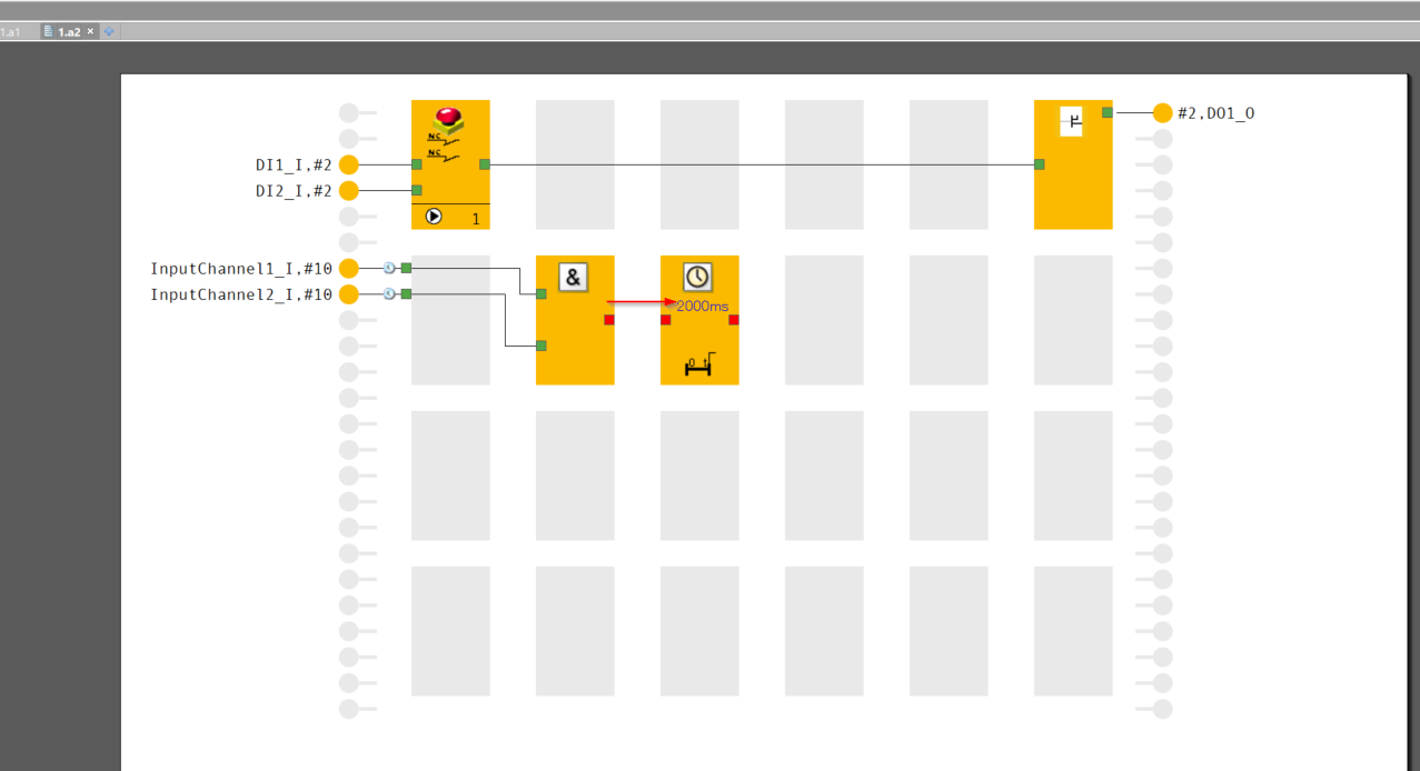
Add Time Element
Add the Timer Element to the Function Sheet.
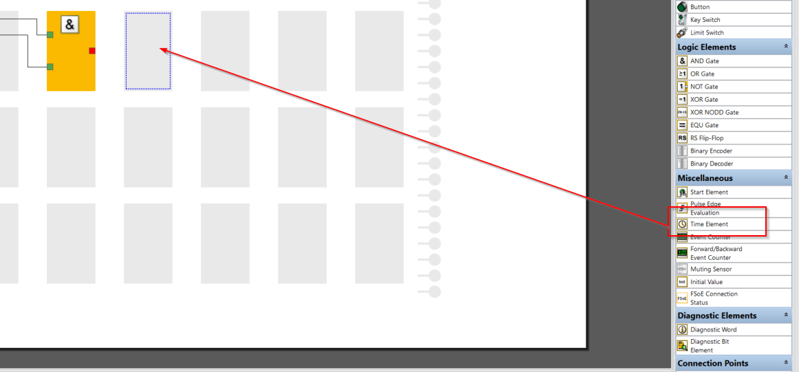
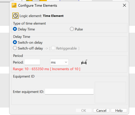
The Time Elements setup screen will appear.
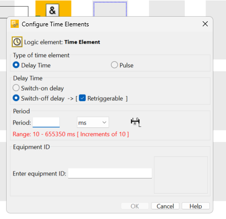
Delay Time
Delay ON and Delay OFF can be set for Delay Time.
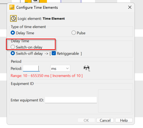
In this article, we will set Switch-on delay (delay ON).
Period
Period allows you to set the delay time and units for the relevant Time Elements.
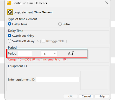
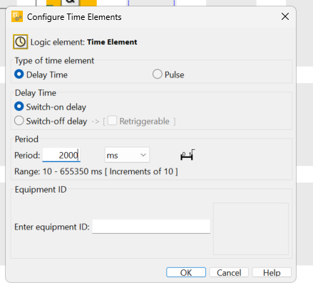
For this article, 2000 ms (2 seconds) is set.
You can change the unit of delay in the adjacent Drop-List.
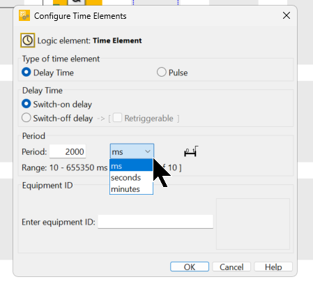
Done!Time Element has been added.
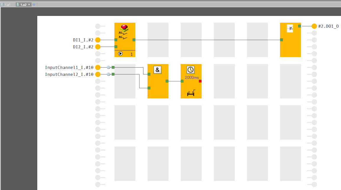
Connect AND Blocks to Timer Input
Now the output of ANG Gate is connected to the input of Time Element.
This is Ok.
Connect to Safety Output
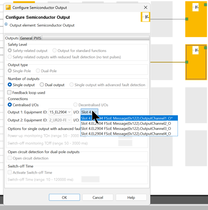
Finally, let’s connect with the EL2904’s Channel 1 output.
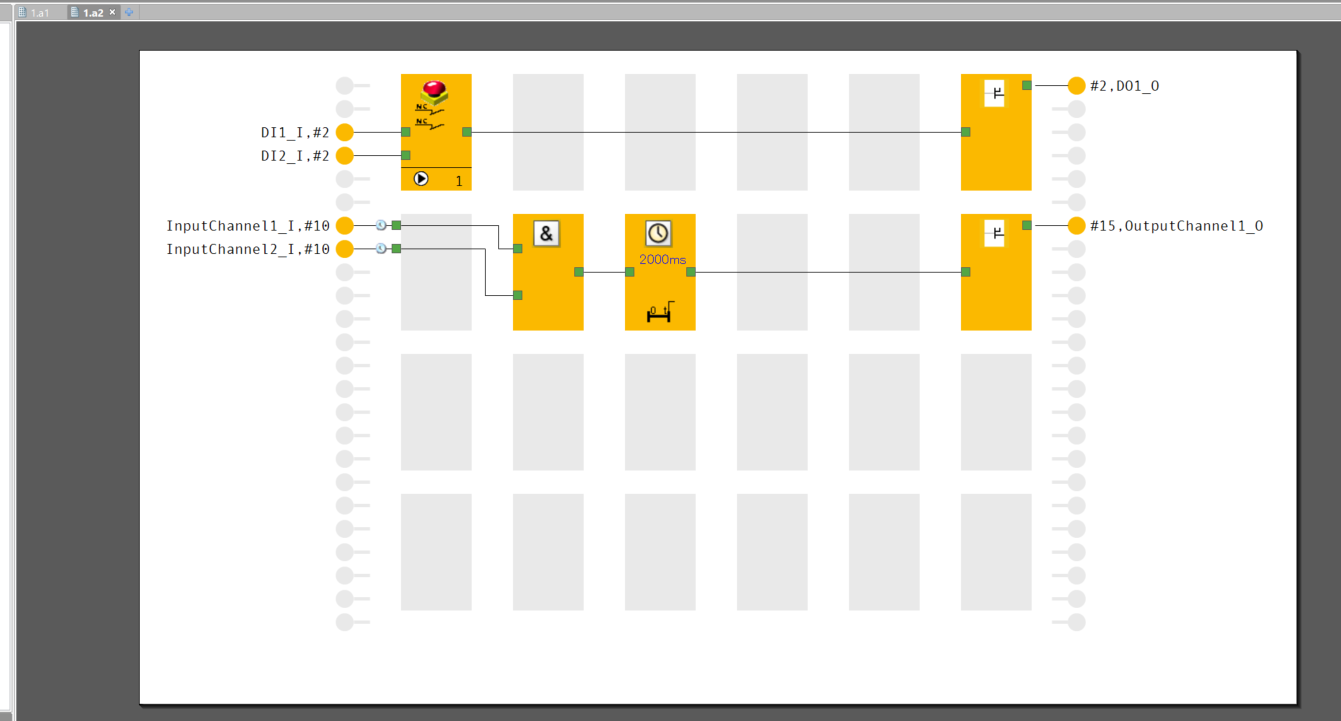
Set the Equipment ID to EL2904.
Set I/O to Channel1_O and it is Ok.
Add EtherCAT Inputs
Adds non-safe EtherCAT communication: input data via EtherCAT Fieldbus are processed as ESTOP resets.
Now, first double-click on the E-STOP Function Element.
Open the Start Tab and set Start Type to Manual Start.
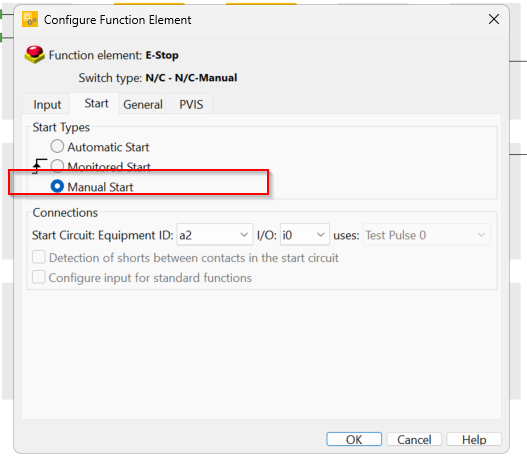
Done!
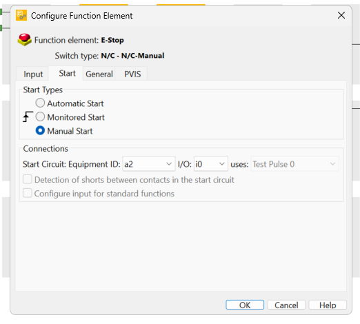
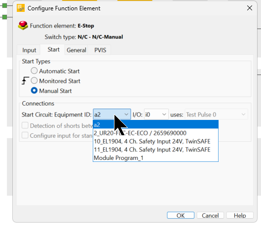
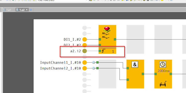
The Equipment ID can be set to the reset signal of the E-STOP Function Element and the module to be connected. In this case, it is set to a2 (EtherCAT FSOE module name).
I/O can be set to the input Point of the corresponding module.
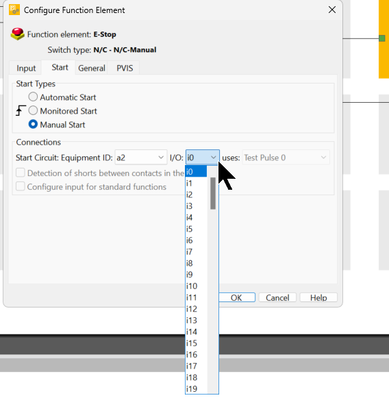
This time, set to I2 and use the 0th and 2nd Byte for non-safe EtherCAT communication.
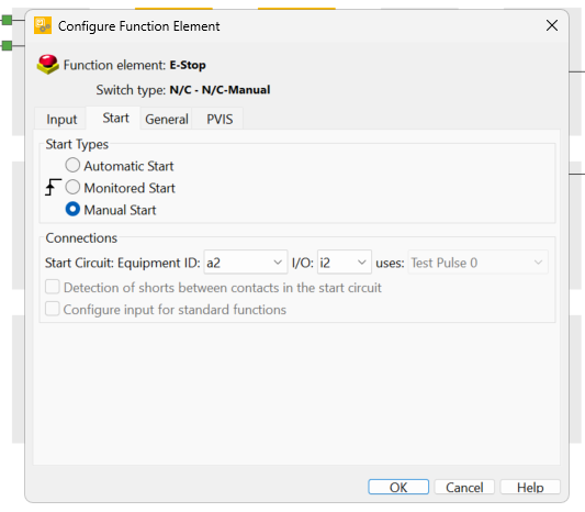
Done!
Add EtherCAT Outputs
The last step is to set the output data for non-safe EtherCAT.
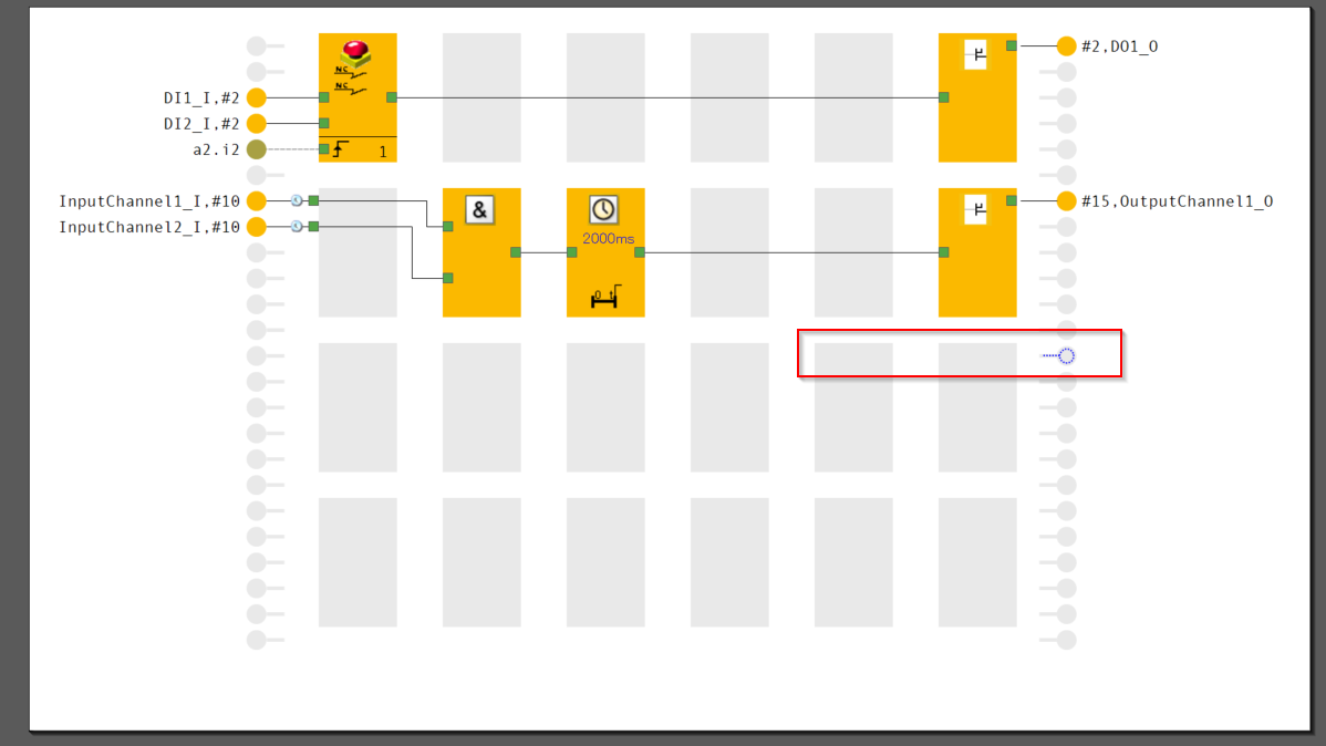
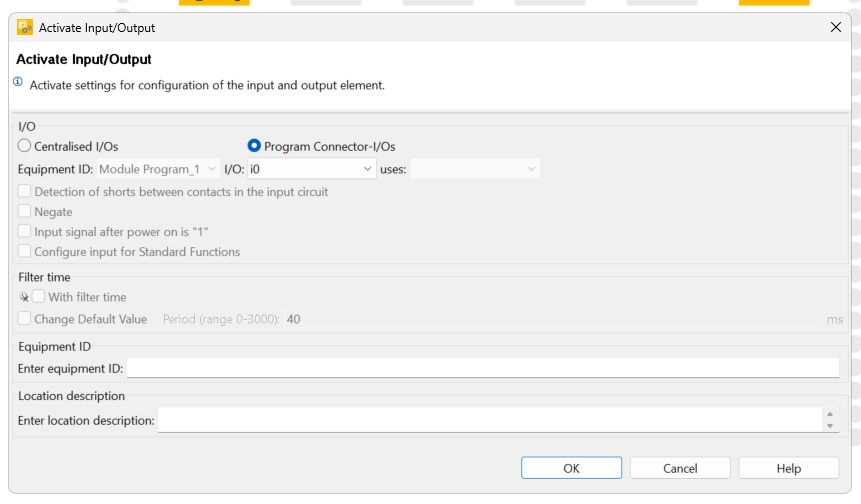
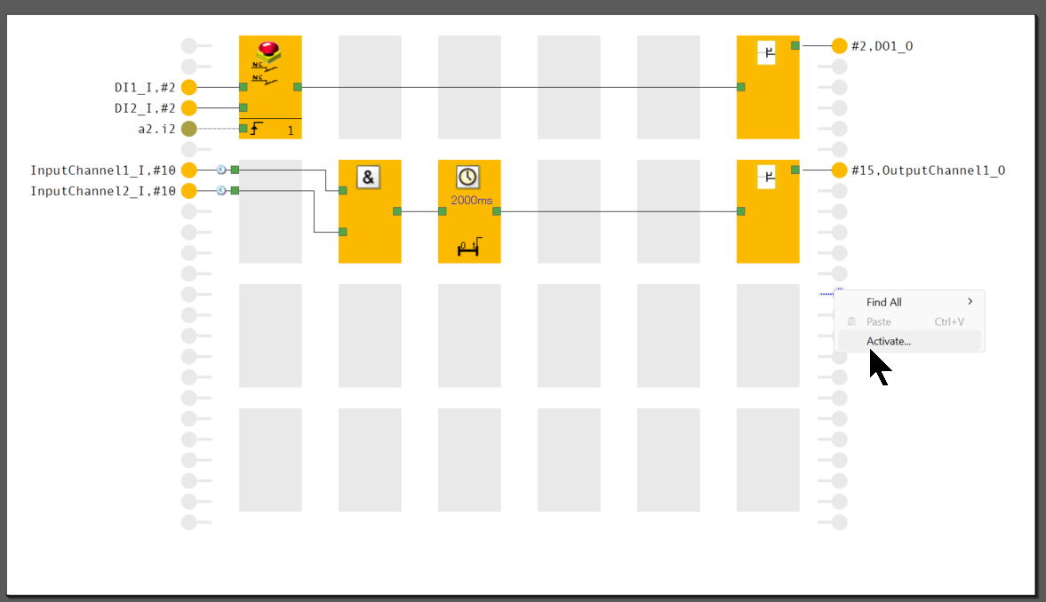
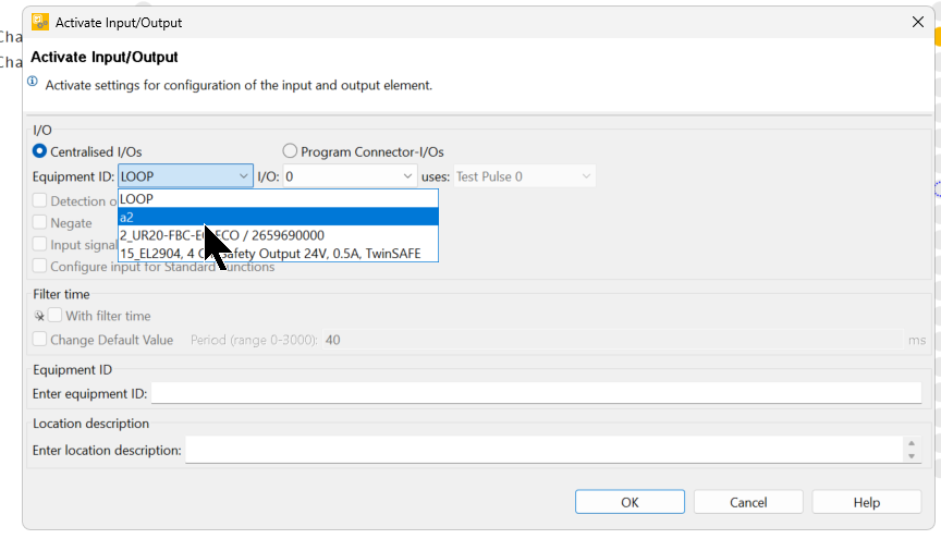
Right-click on an output point not used in the Function Sheet>click Activate.
The I/O configuration screen also appears.
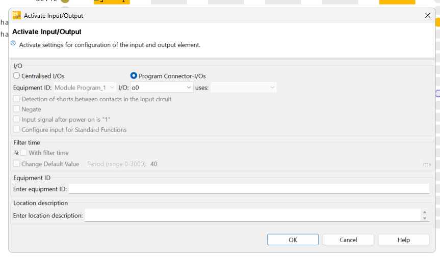
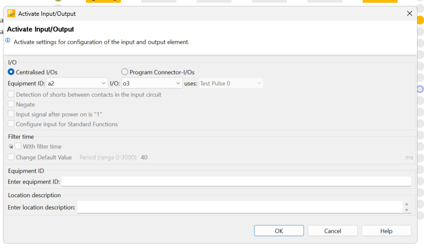
The Equipment ID can be set to the output signal and the module to be connected. In this case, it is set to a2 (EtherCAT FSOE module name).
I/O can be set to the output Point of the corresponding module.
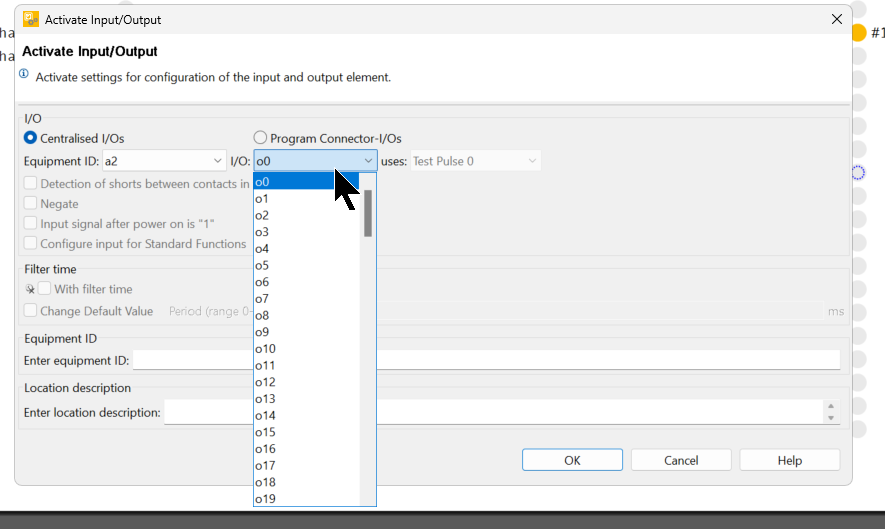
This time, set to o3 and use the 0th and 3rd Byte of non-safe EtherCAT communication.
Finally, connect the output of Time Element with the output point of EtherCAT.
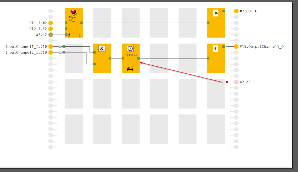
Done!
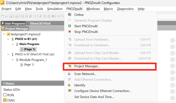
Download
To Download a project, click PNOZmulit>Project Manager.
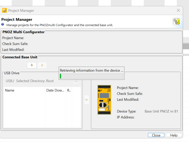
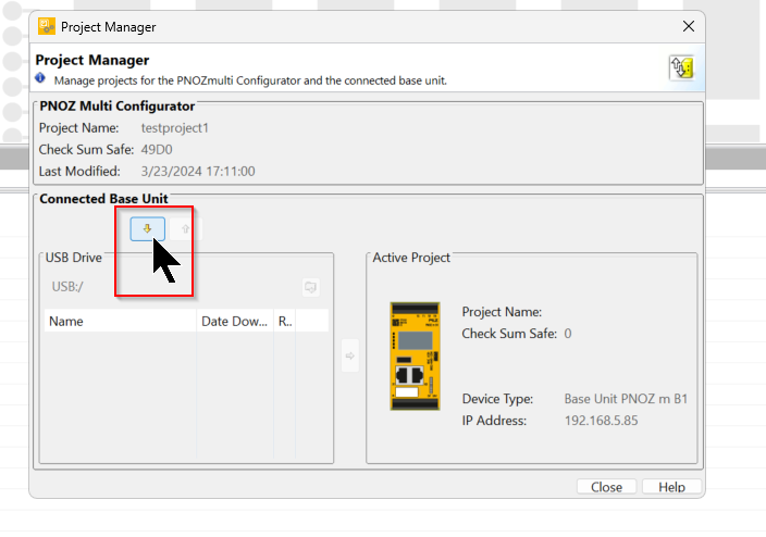
The Download screen appears.
Click the button in the red frame to download the project.
Enter the Order Number and Serial Number of the CPU.
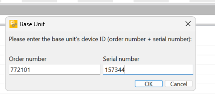
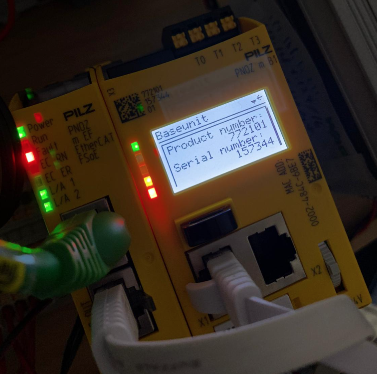
Order Number and Serial Number can be checked from the CPU screen.
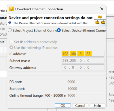
To change the Ethernet Connection, click “Select Device Ethernet Connection” and press OK to proceed.
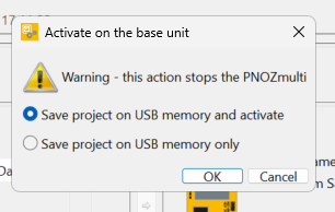
Select “Save project on USB Memory and activate” and press Ok to proceed.
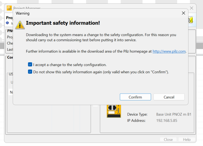
Check the notes and proceed with Confirm.
Please wait a moment as the Download starts.
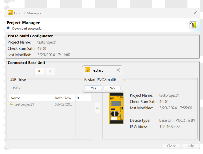
The “Do you want to restart the PNOZmulit CPU from the tool? confirmation screen will appear, and proceed with Yes.
TwinCAT3 Side
Install ESI File
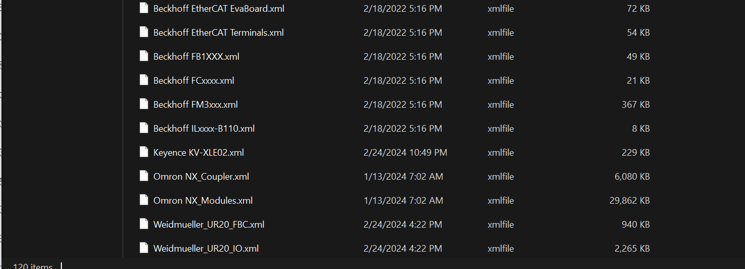
Please store the ESI File downloaded from weidmueller and PilzHP in the following Directory.
C:\TwinCAT\3.1\Config\Io\EtherCAT
Add EtherCAT Master
To add an EthernetCAT Master, go to I/O>Devices>right click>Add New Item.

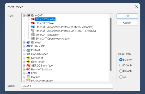
Select EtherCAT>EtherCAT Master and proceed with Ok.
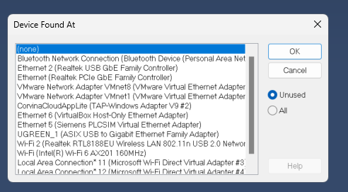
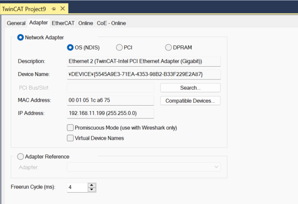
Select the Ethernet Interface to be used as EtherCAT Master and press OK to proceed.
Done!
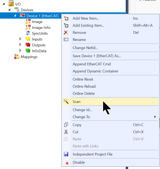
Auto Scan
Use the Auto Scan function to search for EtherCAT Slaves in the network.
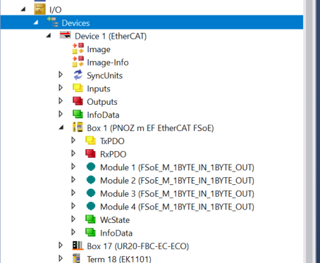
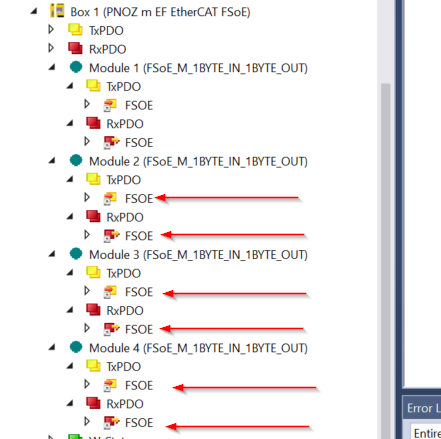
The PNOZ m EF EtherCAT FSoE module has been found and added to the EtherCAT network.
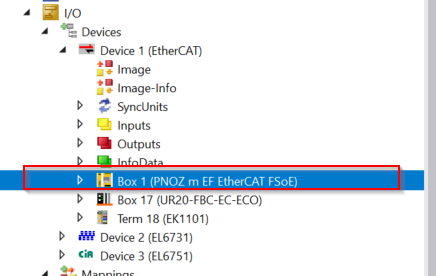
It was also automatically added to the four Slots you just set up in PNOZ m EF EtherCAT FSoE.
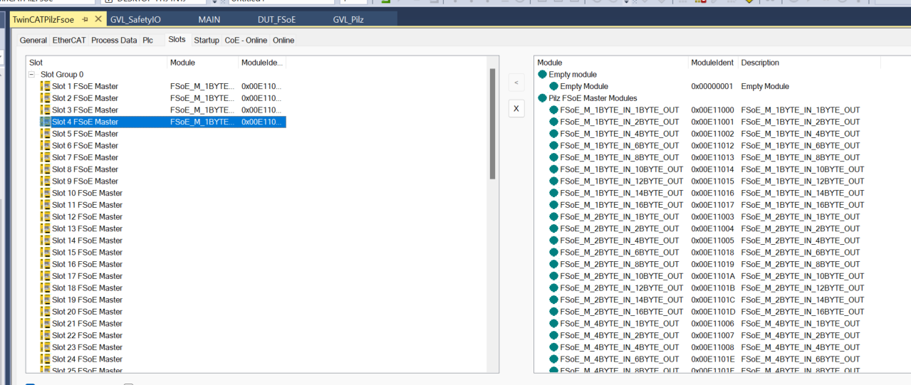
If you want to add a Slot in Manual, open the Slots tab and configure it for your application.
Program
Now we can add the PLC program.
DUT_FSoE
Defines a structure for messages with FSoE 1Byte input.
| TYPE DUT_FSoE : STRUCT MasterCMD :USINT; SafetyOut0 :BYTE; MasterCRC0 :UINT; MasterConnID:UINT; END_STRUCT END_TYPE |
GVL_Pilz
This is the variable to be Mapped to the Pilz module.
| {attribute ‘qualified_only’} VAR_GLOBAL Slot1_i AT %I*:DUT_FSoE; Slot1_q AT %Q*:DUT_FSoE; Slot2_i AT %I*:DUT_FSoE; Slot2_q AT %Q*:DUT_FSoE; Slot3_i AT %I*:DUT_FSoE; Slot3_q AT %Q*:DUT_FSoE; Slot4_i AT %I*:DUT_FSoE; Slot4_q AT %Q*:DUT_FSoE; VirtualOutputs AT %I*:ARRAY[0..15]OF USINT; VirtualInputs AT %Q*:ARRAY[0..15]OF USINT; END_VAR |
GVL_SafetyIO
This is the variable to be Mapped to each FSoE Slave.
| {attribute ‘qualified_only’} VAR_GLOBAL Slot1_i AT %I*:DUT_FSoE; Slot1_q AT %Q*:DUT_FSoE; Slot2_i AT %I*:DUT_FSoE; Slot2_q AT %Q*:DUT_FSoE; Slot3_i AT %I*:DUT_FSoE; Slot3_q AT %Q*:DUT_FSoE; Slot4_i AT %I*:DUT_FSoE; Slot4_q AT %Q*:DUT_FSoE; END_VAR |
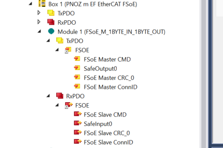
MAIN
The PDO from the FSoE Slave must Loopback to the PDO from the FSoE Master, and each FSoE Connection has a TxPDO and an RxPDO. PDOs are also bi-directional connections, sending data from the FSoE Master to the FSoE Slave.
So, the following program will Loop Back the RxPDO of Pilz to the TxPDO of each Safety IO, and the RxPDO of Safety IO will be the same operation.
| ESTOPStatus:BOOL; bReset:BOOL; TON:TON; GVL_SafetyIO.Slot1_q:=GVL_Pilz.Slot1_i; GVL_Pilz.Slot1_q:=GVL_SafetyIO.Slot1_i; GVL_SafetyIO.Slot2_q:=GVL_Pilz.Slot2_i; GVL_Pilz.Slot2_q:=GVL_SafetyIO.Slot2_i; GVL_SafetyIO.Slot3_q:=GVL_Pilz.Slot3_i; GVL_Pilz.Slot3_q:=GVL_SafetyIO.Slot3_i; GVL_SafetyIO.Slot4_q:=GVL_Pilz.Slot4_i; GVL_Pilz.Slot4_q:=GVL_SafetyIO.Slot4_i; ESTOPStatus:=GVL_Pilz.VirtualOutputs[0].3; TON(IN:=bReset,PT:=T#1S); GVL_Pilz.VirtualInputs[0].2:=bReset; IF TON.Q THEN bReset:=FALSE; END_IF |
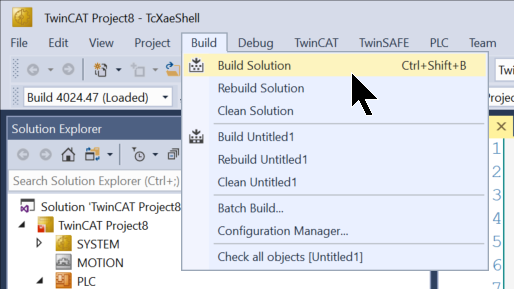
Build
Compile the project under Build>Build Solution.
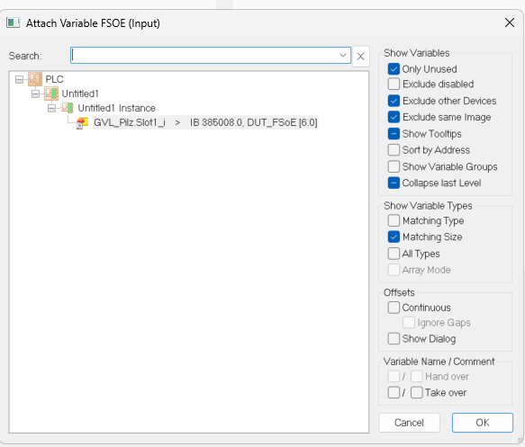
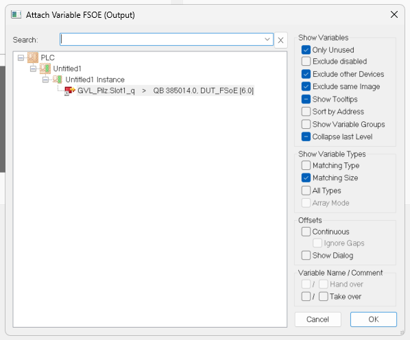
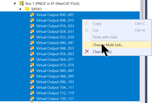
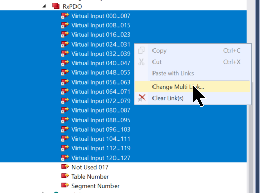
Link Inputs/Outputs
Finally, let’s Mapping each Module and Variable.
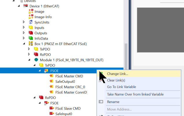
Basically, if the structure and data size are the same, it can be mapped as is.
Mapping is done in the same way for Module1 and RxPDO on the Pilz module side.
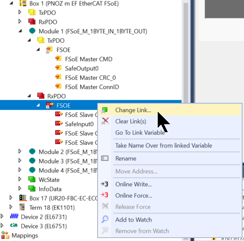
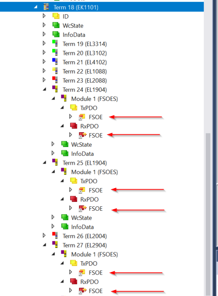
The remaining modules should also be tied to program variables.
- Module 2(EL1904,FSOE Address=10)
- Module 3(EL1904,FSOE Address=11)
- Module 4(EL2904,FSOE Address=15)
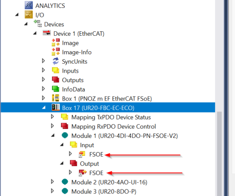
Let’s also Mapping to FSOE Messge on UR20-4DI-4DO-PN-FSOE-2 side.
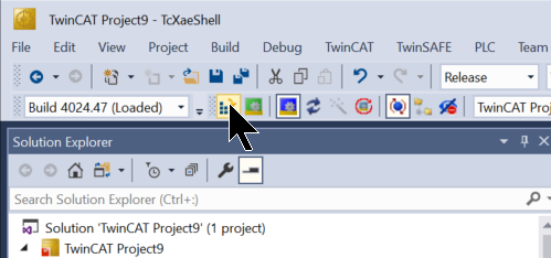
Activate Configuration
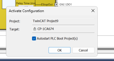
Finally, click Activate Configuration to download the hardware configuration, etc.
OK to proceed.
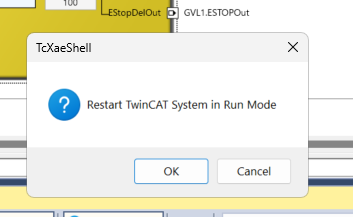
Shift to Run Mode.
Result
Pilz’s FSoE Master can connect to all FSoE Slaves.
The safety program is also operating normally.
You can see the actual operating conditions from this video.