In this article, I will explain from scratch how to build an EtherCAT network with Beckhoff’s IPC C6920 and Wago’s EtherCAT Fieldbus Coupler. Let’s start!
Thanks!
Because of Beckhoff Japan and Wago Japan that lend the devices to me – I can create this post.
Beckhoff Japan
IPC6920-005 was lent by Beckhoff Japan, a Japanese subsidiary of Beckhoff. Founded in 1980, Beckhoff Automation is a German company at the forefront of the introduction of open automation systems based on PC-based control technology.
Beckhoff Japan Corporation Beckhoff Automation Co., Ltd. established its head office in Yokohama in 2011 and the Nagoya office in 2017.

Here is the Home page of Beckhoff Japan.
https://www.beckhoff.com/ja-jp/
Wago Japan
750-354 EtherCAT Coupler is lent by Wago Japan Co., Ltd. WAGO was started in 1951, a German company that has supported the field with the technologies of PUSH WIRE and CAGE CLAMP, and have contributed to industries around the world with terminal block technology. WAGO also has a PLC LINEUP, offering automation solutions with an emphasis on openness and flexibility.
Wago Japan Co., Ltd. is headquartered in Koto-ku, Tokyo.

Video
Japanese Version
Video-English Version
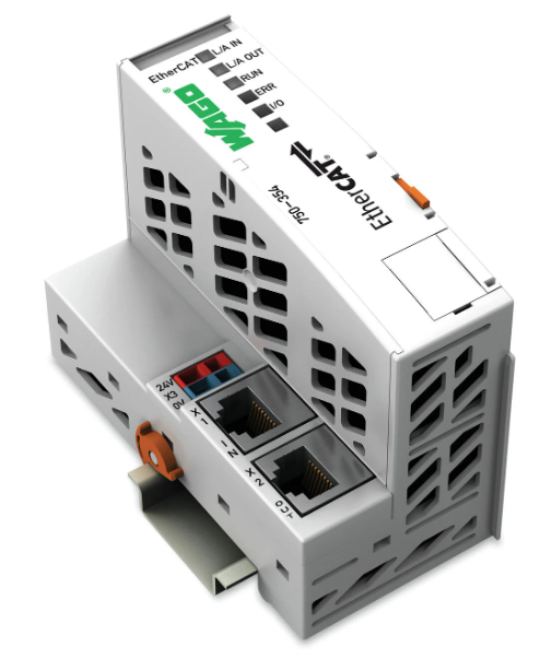
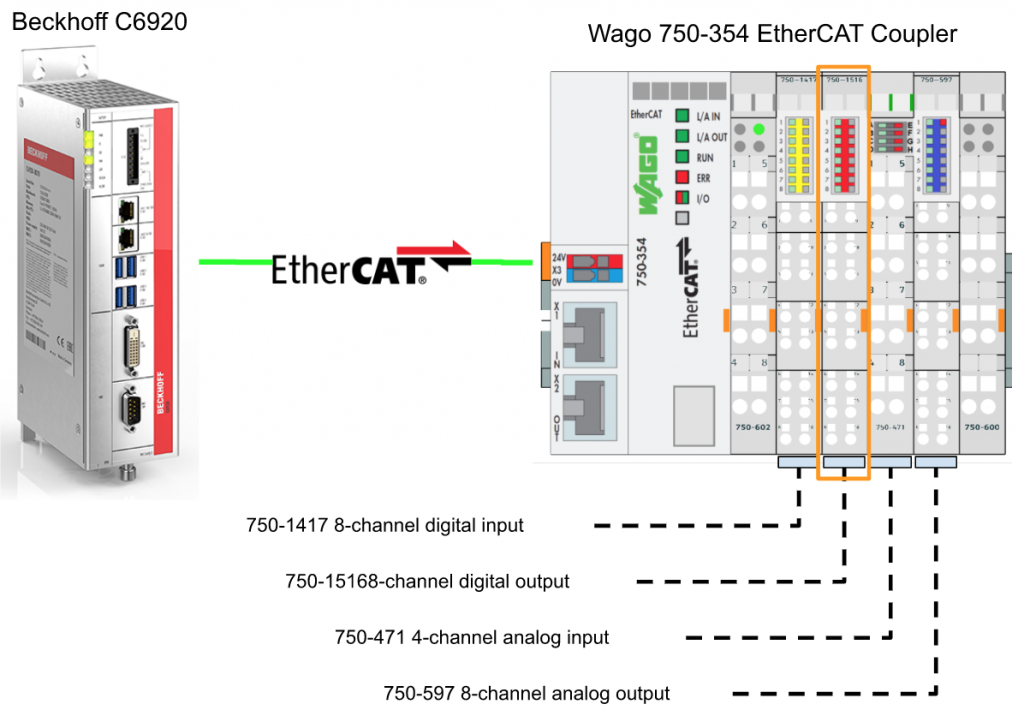
750-354 EtherCAT Coupler
The 750-354 Fieldbus Coupler can integrate the WAGO-I/O SYSTEM into the EtherCAT network. A coupler has one In Port and one Output Port, and Topology such as Linear can be easily realized.
Analog and special modules are created in the Local Process Image in Byte units, and digital modules are created in the Local Process Image in Bit units.
The local process image is divided into two zones, transmission and reception, and the analog module is first mapped to the process image, and then becomes the IO of the digital module.
Power supply
Please Connect 24v as shown below, 1=DC24+ and 2 is 0v.

Layout
Here is the Layout of 750-354 EtherCAT Coupler.

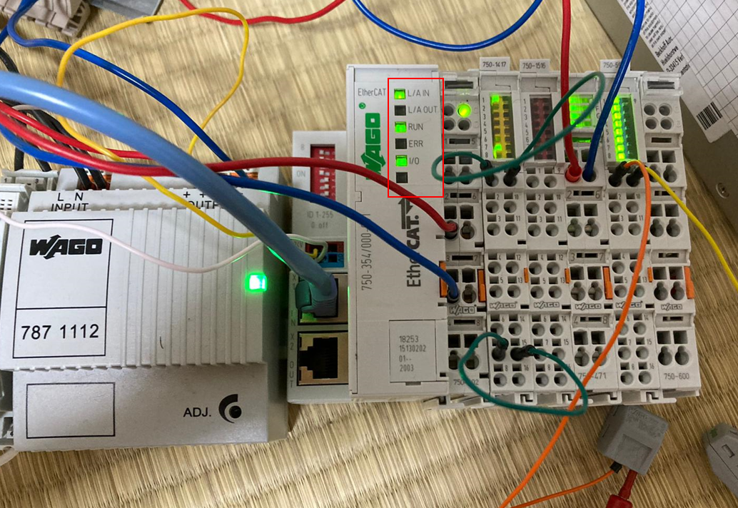
LED
We can use the LED on the 750-354 EtherCAT Coupler to find-out the module status.
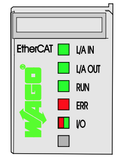
| LED | Color | |
| L/A IN | Green | Network Status of Port X1(INPUT) |
| L/A OUT | Green | Network Status of Port X2(OUTPUT) |
| RUN | Green | EtherCAT Running Status |
| ERR | Red | Fieldbus Error |
| I/O | Red/Green/Orange | Node Operation Status |
Startup
Once the EtherCAT Master has been built and the 750-354 EtherCAT Fieldbus Coupler has been powered up, the Fieldbus Node is ready for operation.
The Fieldbus Coupler first enters the Initialization state, and the Fieldbus Coupler Firmware starts in the Initialization Phase. The I/O LED is red when Firmware is booting.
When I/O module status is connected to the Fieldbus Coupler, the I/O LED is blinking red. If there are no errors the Fieldbus Coupler will switch to INIT Status. If the module encounters an error while booting, the I/O LED will remain red.
Data Exchange
Of course, the 750-354 is an EtherCAT Fieldbus Coupler, so it uses the EtherCAT Protocol to exchange IO data with the Master. EtherCAT exchanges IO data with Master/Slave, and the EtherCAT Master Controller is also possible with a PC or PLC.
750-354 is a Slave, and there are two Main Interface for Cyclical data exchange inside.
- FieldbusのInterface(Fieldbus Master)
- I/O ModuleのInterface
Fieldbus Coupler is used to exchange IO Data between EtherCAT Master and Wago I/O modules. EtherCAT Master outputs Output Process Data to Fieldbus Coupler and receives Fieldbus Data. The Process Image Size is up to 1024 Bytes.
Overview
The WAGO-I/O-SYSTEM 750 as well as the WAGO 750-354 have a wide variety of modules.
- Digital Input
- Digital Output
- Analog Input
- Analog Output
- Communication Module
- Power Module
- Special Module
In this tutorial, the common DI/DO/AI/AO are used.
Implementation
Configuration
Wago Side
WagoIO Check
Wago IO Modules (especially other than digital inputs) require individual configuration of the module for each Slot and all configured parameters are saved in the IO Module itself.
Communication Setting
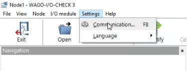
Open the Wago-I/O-Check>Settings>Communication.
Choose the Connection Interface.

Seaech
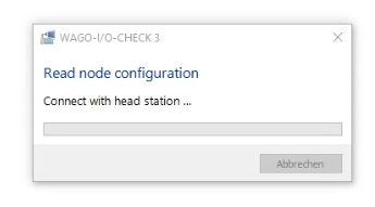
Click the Identify(F5) to Search the 750-354 EtherCAT Coupler.

Please wait a minute..
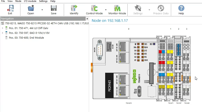
750-333 is shown.
750-471 Setting
We can configure the analog input by clicking the analog input channel.
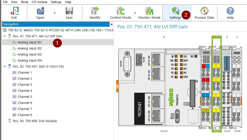
The current parameters for each Channel are displayed.

Let’s change the parameters of Channel1.
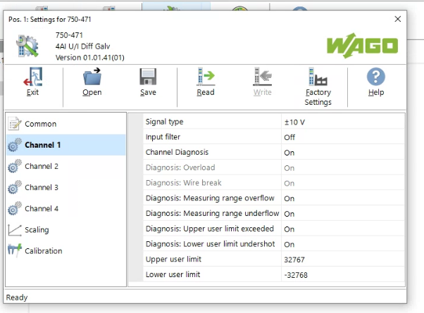
Let’s Change the Signal type from -10v to 10v to 0v to 10v.
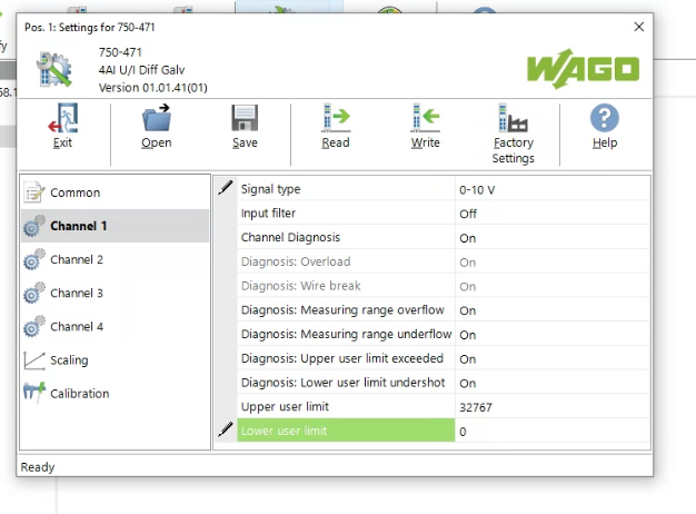
After changing the Lower user Limit to 0,now the voltage range from 0v to 10v is 0-32767.

Press the Write Button to download the parameters into the module.
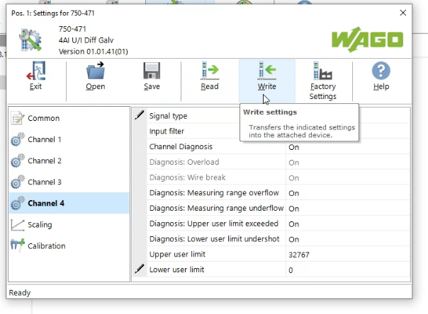
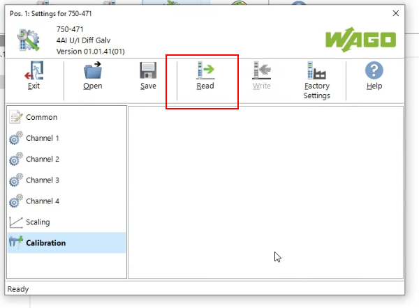
Let’s double check the parameters by pressing the Read Button.
750-597 Setting
Now we can change the analog output module.Select the Analog module>Click the Settings.

Check the Range of each Channel in Channel settings. 0-10v is used in my Tutorial.
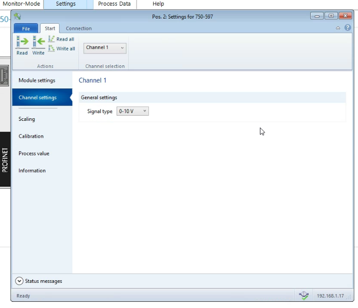
Press “exit” to end the set-up.
TwinCAT Side
Download ESI File
Access the link below and download the 750-354 EtherCAT Coupler ESI File from Wago’s site.
https://www.wago.com/global/i-o-systems/fieldbus-coupler-ethercat/p/750-354#downloads

Zip File is downloaded.

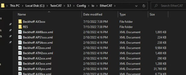
Update Device List
Unzip the file and copy it to \TwinCAT3\3.1\Config\io\EtherCAT.
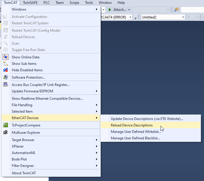
Go to TwinCAT>EtherCAT Devices>Reload Device Descriptions to update your Device List/
Add EtherCAT Master
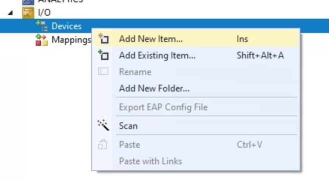
Go to I/O>Devices>Right Click and Add New Item.
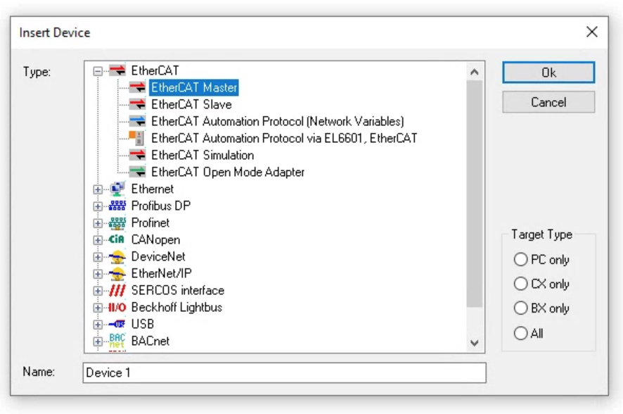
Choose EtherCAT Master from EtherCAT>OK.
Select the EtherCAT Interface connected to the EtherCAT Coupler 750-354 and click Ok.
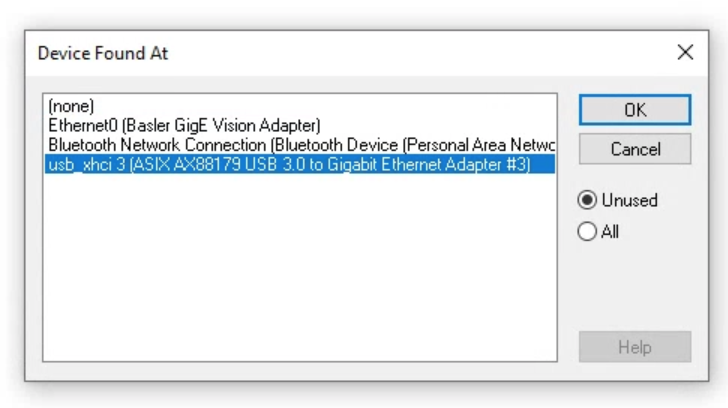
Please double check if the interface that you configured is correct or not.

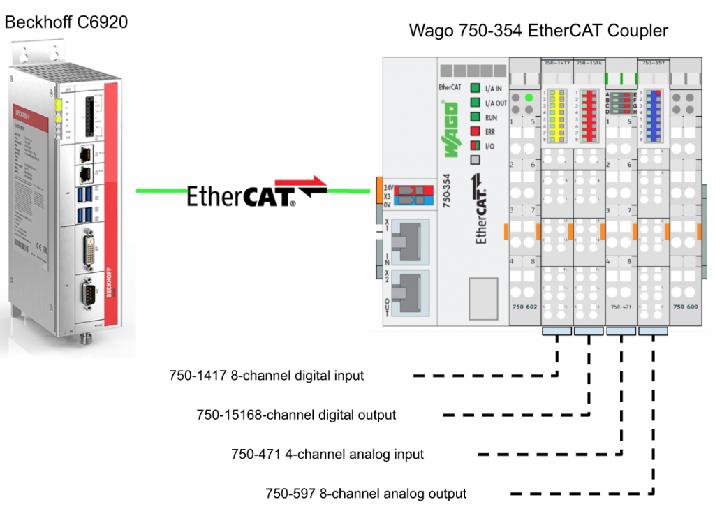
Add Wago EtherCAT Coupler
Now we can insert the Wago 750-354 EtherCAT Coupler into your EtherCAT Network.
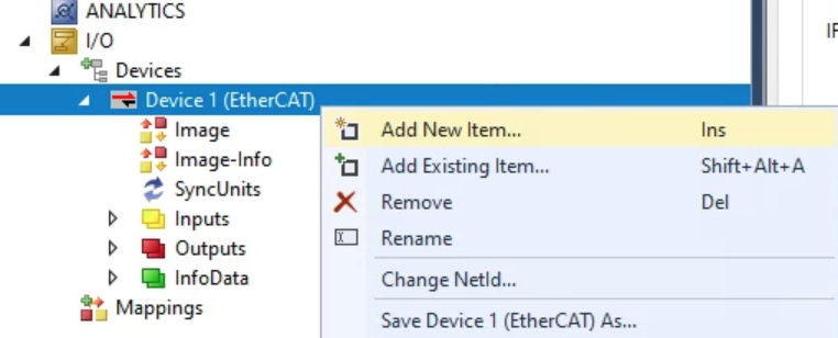
Go to Devices1(EtherCAT)>Right Click>Add New Item.
Go tWAGO>750-354/000-0001 EtherCat fieldbus coupler>OK.
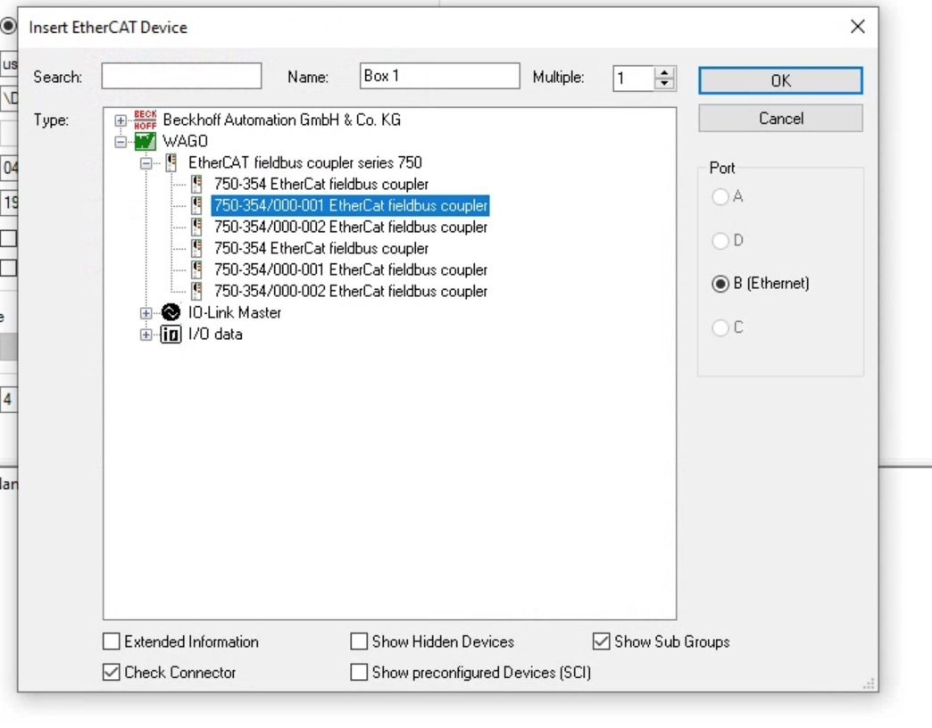
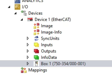
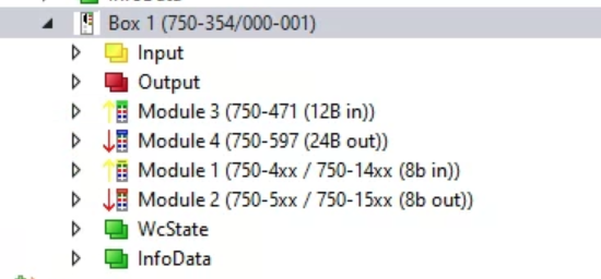
Wago 750-354 EtherCAT Coupler is inserted in your network.
Add Slot
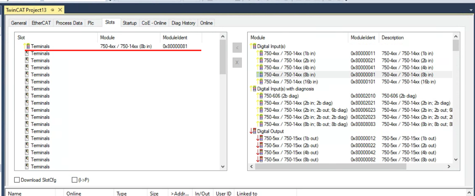
Double Click the Box and open the Slots Tab .

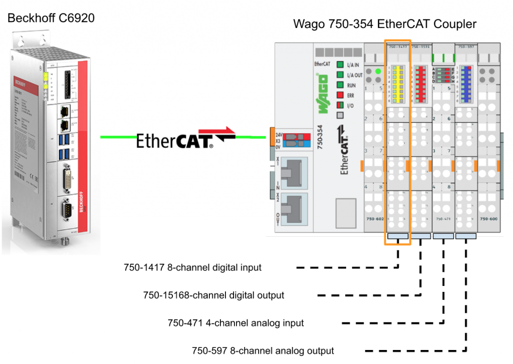
750-1417 8-channel digital input
Let’s Install 750-1417 8-Channel Digital Input into Slot1.
Click the 1st Terminals>Choose 750-4xx/750-14xx(8b in) and click the “<” Button.

750-1417 is inserted in Slot1.
750-1516 8-channel digital output
Let’s Install 750-1516 8-Channel Digital Output into Slot2.
Click the 2nd Terminals>Choose 750-5xx/750-15xx(8b out) and click the “<” Button.

750-1516 is inserted in Slot2.
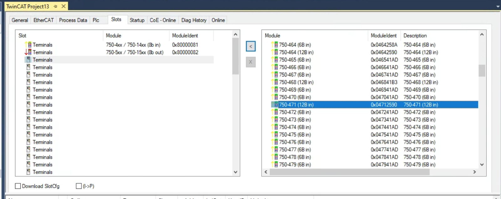
750-471 4-channel analog input
Let’s Install 750-471 4-Channel Analog Input into Slot3.
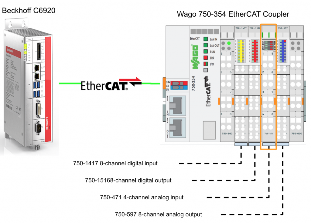
Click the 3rd Terminals>Choose 750-471(128b in) and click the “<” Button.

750-471 is inserted in Slot3.

750-597 8-channel analog output
Let’s Install 750-597 4-Channel Analog Output into Slot4.
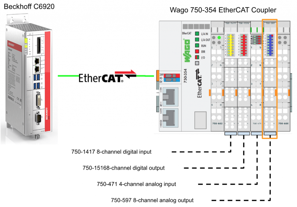
Click the 4th Terminals>Choose 750-597 and click the “<” Button.

750-597 is inserted in Slot4.

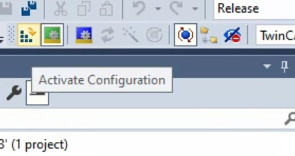
Activate Configuration
Download the Hardware Configuration by pressing the “Activate Configuration” Button.

OK.
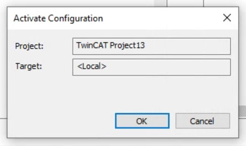
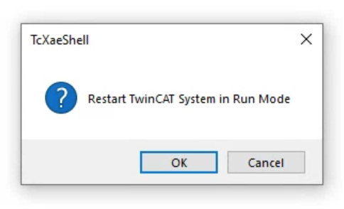
Restart your Runtime.

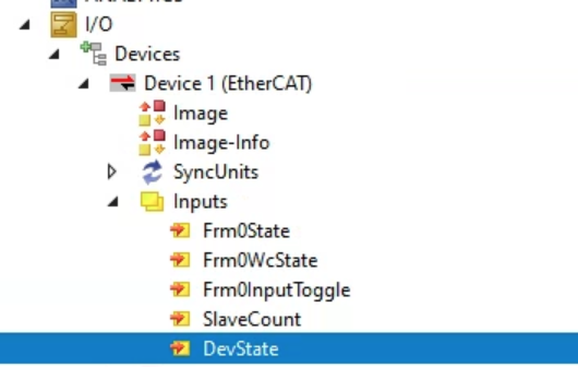
Check Status
Go to EtherCAT Master>Inputs>DevState to confirm the connection status.

Then we can click the Box.
Go to the Online tab and you can see the Wago 750-354 Ethercat Coupler is in PREOP status.It is because there are no user program variables linked to the process IO images.

Add PLC
Go to PLC>Right Click>Add New Item.

Choose Standard PLC Project>Add.

DUT
Now we can create the Data unit Type.
DUT_8CHAN
Define a Data Unit Type for 8 channel Analog modules.

DUT_8CHDI
Define a Data Unit Type for 8 channel Digital Input/Output modules.

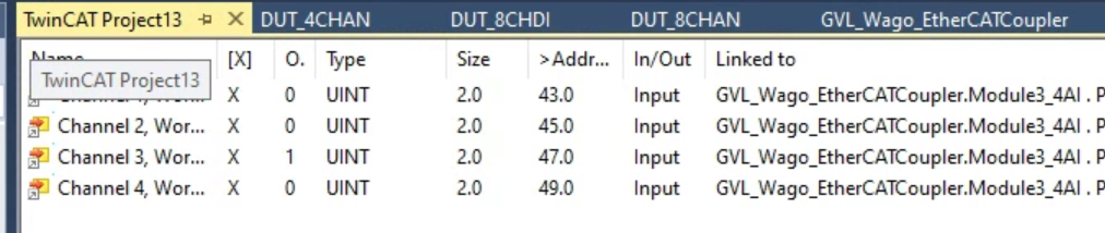
DUT_4CHAN
Define a Data Unit Type for 4 channel Analog modules.

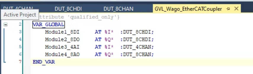
Add GVL
After all Data unit types are defined, we can add GVL into our program. go to GVL>Right Click>Add>Global Variable List.

Enter your GVL name.

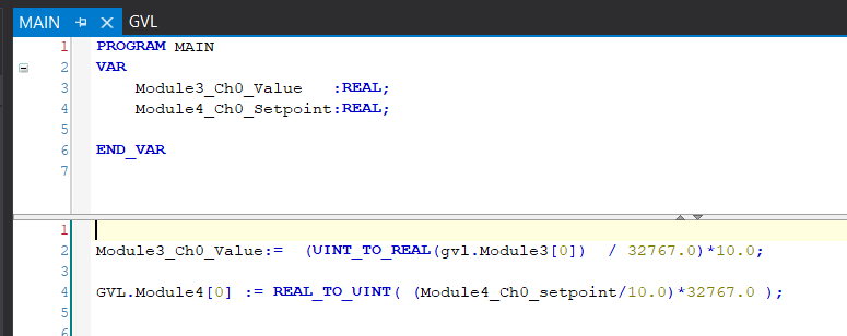
Define process IO variables inside the GVL.
Program
Build a simple scaling program. It just converts analog input input to 0-10v and 0-10v analog output.
Build
Go to Build>Build Solution to compile your project.

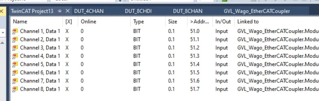
LINK 750-1417 8 Channel INPUT
Let’s link the 1st slot Digital input module to your user program.
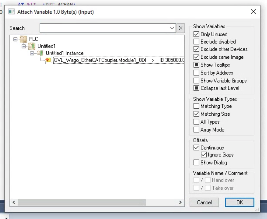
Go to Input(s)>Right Click>Change Multi Link.

Link the process image to the variables inside your user program.
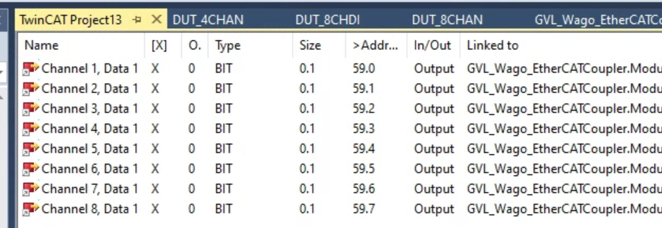
LINK 750-1516 8 Channel Output
Let’s link the 2nd slot Digital Output module to your user program.
Go to Input(s)>Right Click>Change Multi Link.

Link the process image to the variables inside your user program.

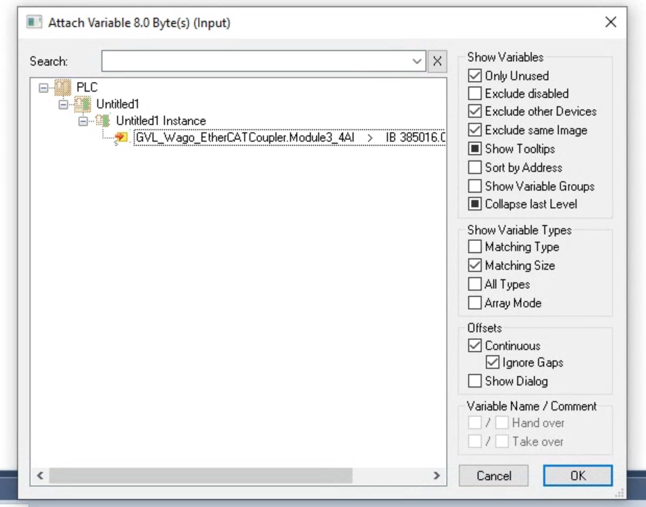
LINK 750-471 4 Channel Analog INPUT
Let’s link the 3rd slot Digital Output module to your user program.
Go to Input(s)>Right Click>Change Multi Link.

Link the process image to the variables inside your user program.
LINK 750-597 8 Channel Analog Output
Let’s link the 4th slot Digital Output module to your user program.
Go to Output(s)>Right Click>Change Multi Link.
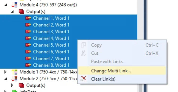
Link the process image to the variables inside your user program.


Activate
Download your hardware configuration again.
Restart the TwinCAT System.
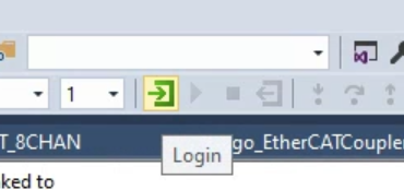
Login
Press Login to Download the User program to the CPU.
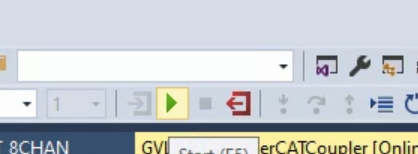
Start
Press Start to run your user program.
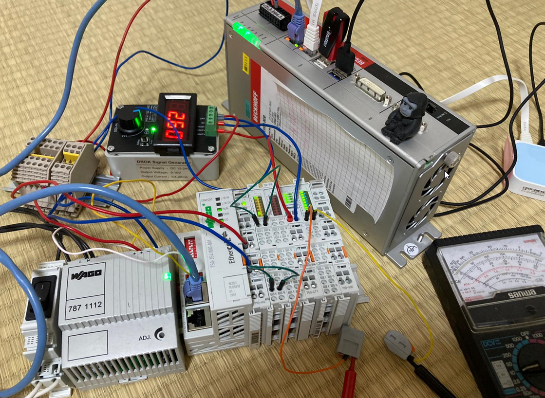
Result
Here is the normal status of the 750-354 EtherCAT Coupler.
And you can find the video from this youtube link.
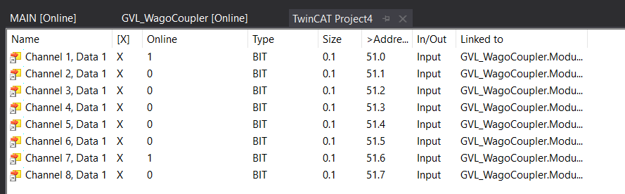
Let’s check the input signal first.

Done!Some signal is received.
And the analog input is around 2.6v.

