This time, I will introduce an example of Configure aIO-LINK Master with Raspberry-pi that with Codesys Runtime.
IOLINK?
First of all, I would like to briefly explain what IOLINK is. Some people may think that IO-LINK is the same Fieldbus as Profinet and EtherCAT, but actually it is not correct.
IO-LINK is a point-to-point communication protocol, not Fieldbus.
First of all, let’s keep in mind that it is a Protocol that communicates with the Sensor.

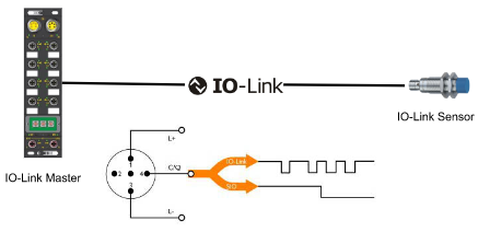
As shown in the figure below, IO-LINK requires IO-LINK Master and IO-Link Devices.
While the IO-Link Master communicates with other IO-Link Devices via the IO-LINK Protocol, it generally stands as a Slave of Fieldbus such as Profinet and Modbus and exchanges necessary information with the host controller.
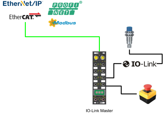
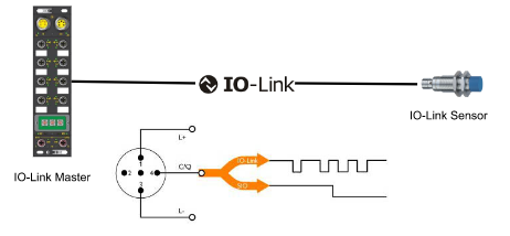
The feature of IO-LINK is not only point-to-point communication but also general Sensor cable. Then, you can choose whether to use it as IO-LINK or normal input / output as needed. With its standard 4-core cable, it can be up to 20 meters.
In other words, only IO-LINK Master has increased. For IO-LINK data, we can look directly at the current value of the Sensor, not the analog value like 4-20mA.
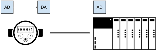
This is a Flow Meter with a typical analog input. Thus, the Flow Meter first converts the flow rate from analog to digital and then Scaling to 4-20mA. Then, it is used as an analog input of PLC and converted into the necessary Engineering Unit inside the program.
There are at least three conversions.
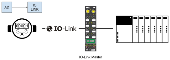
On the other hand, in IO-LINK, the Flow Meter converts the flow rate from analog to digital, passes it to IO-LINK Master, and finally sends it to the PLC via Field bus.
The data received by the PLC is not 4-20mA, but a meaningful digital value.
Sensors have evolved with the times, and there are microprocessors inside,many of them are running Firmware. The amount of information that can be exchanged by using IO-LINK is
increased.
- Device status
- Error code
- Parameters
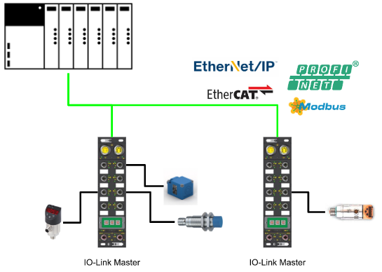
This is a system with a common IO-LINK System. It’s not much different from a typical Fieldbus Network. Just install Sensor as it is, and you will be able to get more information from the Sensor.
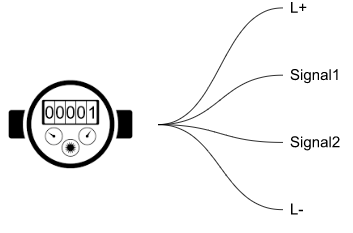
Regarding the amount of information that can be obtained from the Sensor, the conventional system has four lines, and in addition to the two Sensor power supplies, it also has a signal cable. The input / output of the Sensor is generally decided by the manufacturer. For example, Signal1 is an Error and Signal2 is a reset-like mapping.
You may now choose the Signal type of Sensor. But in the end, you can only get two Signals. Finally, the designer decides the Signal to be used from the priority of Signal.
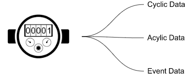
In the case of IO-LINK, you can get 3 types of data. There is Cyclic Data / Acyclic Data / Event Data as shown in the figure below.
- Cyclic Data (cycle)
- Data part that is exchanged periodically.
If it is a Flow Meter, for example:- Scaled Flow value
- Scaled temperature
- Counter
- Data part that is exchanged periodically.
- Acyclic Data
- Internal memory part of Sensor.
- Series Number
- Simulate Mode
- Set value
- Internal memory part of Sensor.
- Event Data
- Additional diagnostic information for Sensor
- history
Configuration
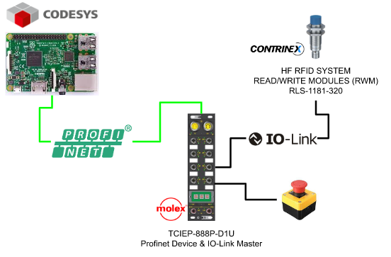
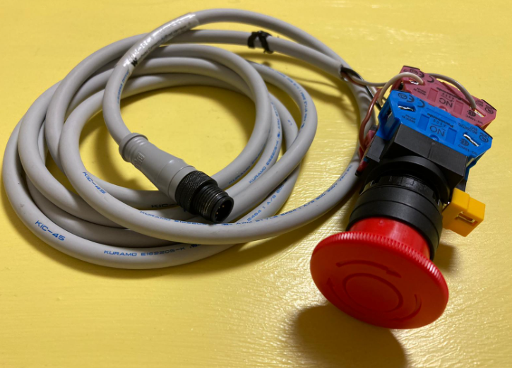
Here is the configuration of my tutorial.we are using a raspberry pi with codesys runtime ,start up as a profinet controller, connect with IO-Link master PN TCIEP-888P-D1U that is made by molex. A normal input and IO link RFID sensor from Conyrinex is connected to this IO-Link master .
Install GSD
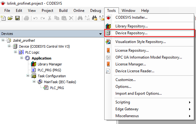
Go to Tools>Device Repository…
Because TCIEP-888P-D1U is a IO-Link master with profinet interface, we need to import the GSDML file into your codesys IDE to configure the profinet network.
Go to tools>Device Repository.
Click the install button.

Choose the GSDML file and open it.

Now the TCIEP-888P-D1U is imported into your Codesys IDE.

Network Configuration
Now we can configure our network.The flow is insert the Ethernet Adapter>insert PN controller > insert PN devices> configure the parameters.
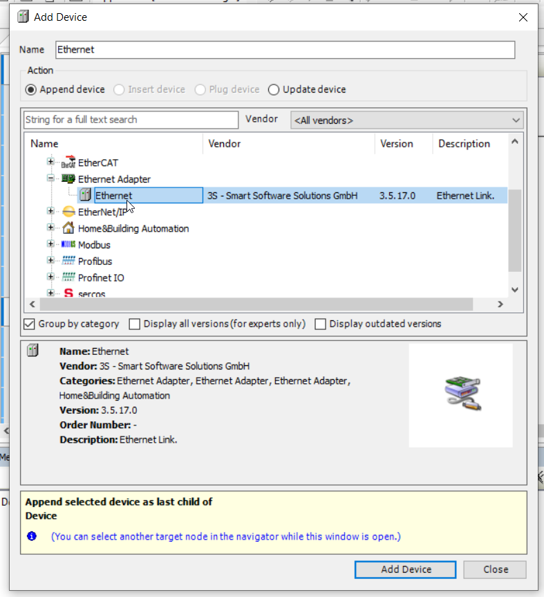
Add Ethernet Adapter
right click the device and choose Add Device.

Choose Ethernet Adapter>Ethernet and Add Device.
Add PN Controller
Then insert the profinet Io controller by Profinet IO>profinet IO master >PN-controller.

Add PN Devices
Finally insert the IO-Link master by Profinet IO Device>I/O>HarshIO 600 IOL.
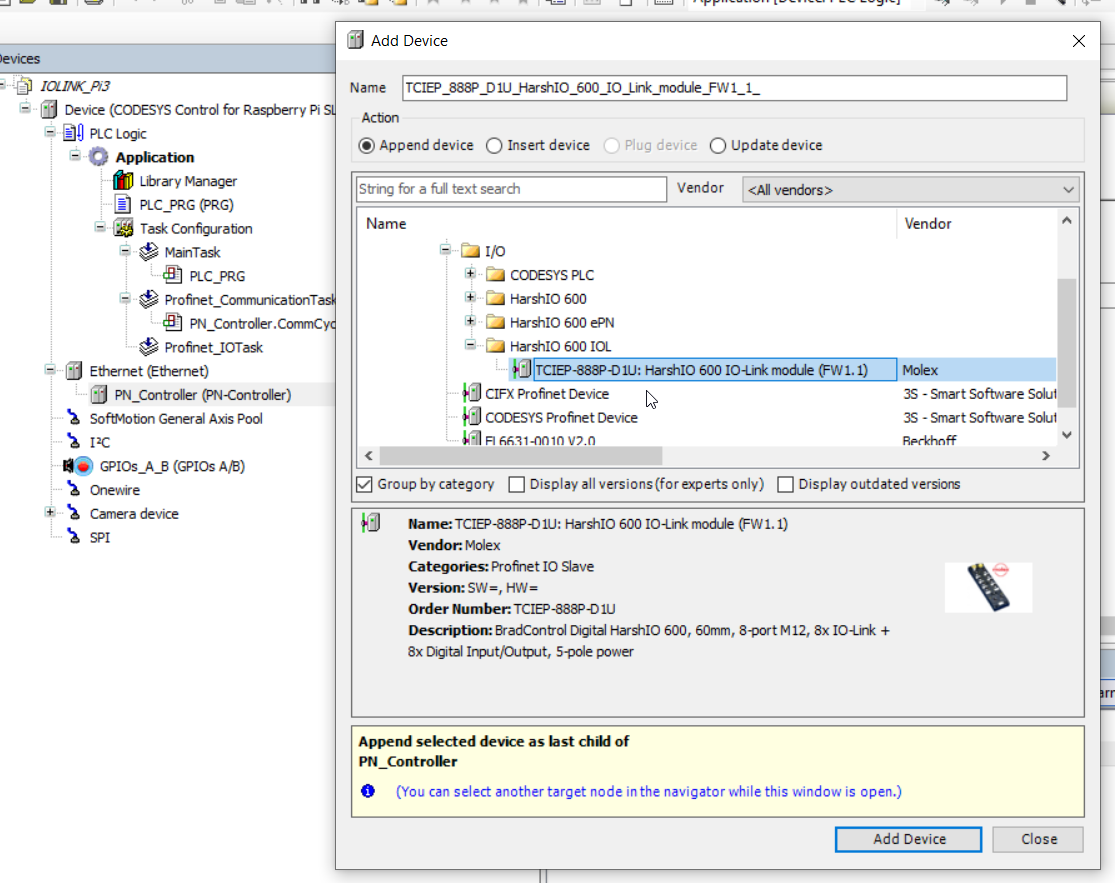
The network is configured.

Set Ethernet Adapter IP
Click the Ethernet Adapter to set up the Network Interface.

Gernal>Browse.
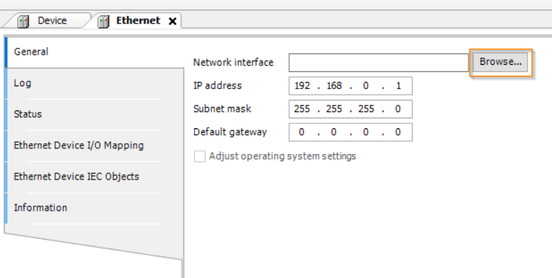
Choose your network card that is connected in the profinet network.

Set PN Controller IP
Set up the PN Controller IP.

Go to General>Station name and input the Ip range in the Default Slave IP parameter field that is inside your subnet.
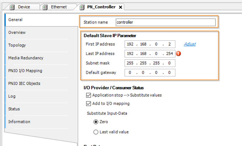
in my case,the network is 192.168.1.x.

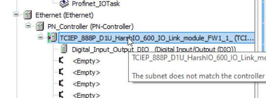
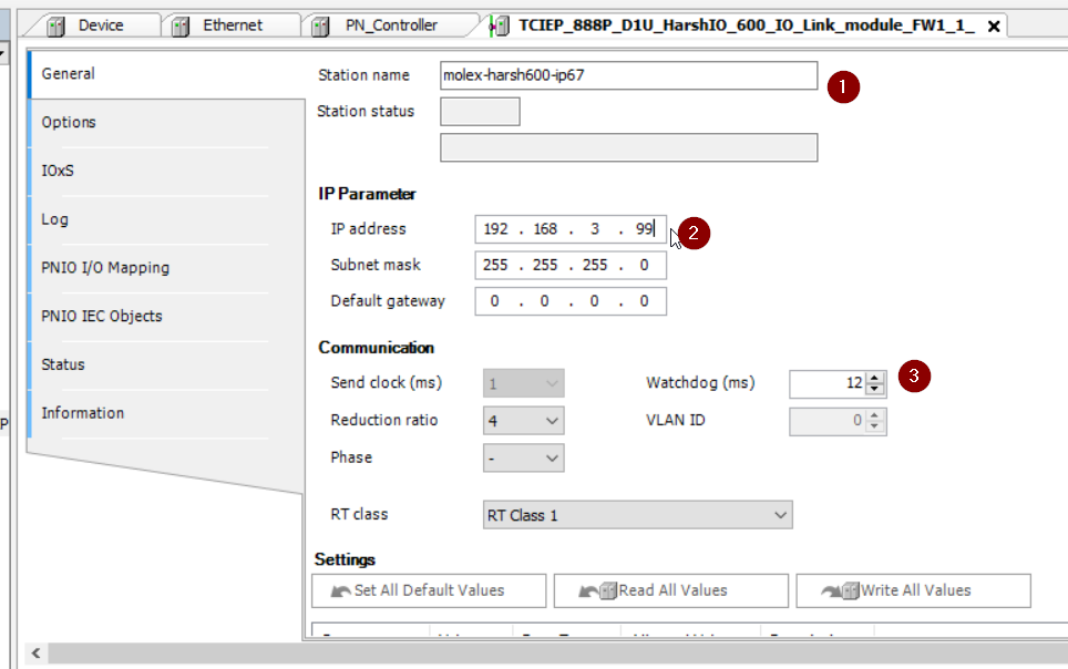
Set PN Devices IP/Device Name
Device Name is very important in the profinet system and profinet controller will assign the Ip address depending on the device name.
Open the General Tab and enter your Station name and ip Parameter.
You may also need to adjust the watchdog in your application.
Assgin Device Name
Before we use the Codesys IDE to assign the profinet device name, download the project to your runtime first and the runtime will install the codesys profinet stack.


right click the PN Controller>Scan for devices.
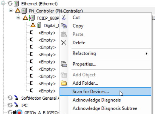
Click the Scan devices.

All devices connected in the profinet network are shown in the popup screen.
Select the TCIEP-888P-D1U module and enter the device name in the station name field.

Click the Set name and IP button.
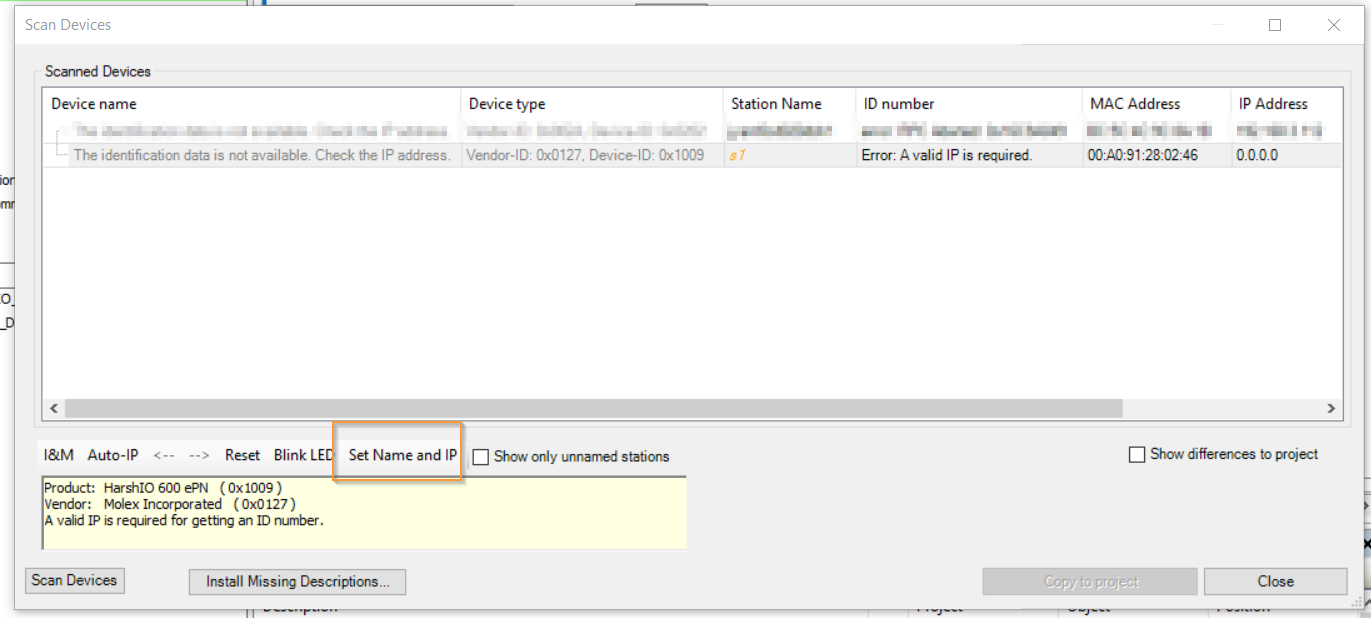
Use the scan device function again and the IP address is also assigned to the TCI-888P-D1U automatically.

Change your codesys runtime state to run , green icon is displayed if the profinet network is in normal mode.

Plug A Normal Input
Firstly I will plug a normal input into TCIEP-888P-D1U. For the IO-Link master you can use the normal input instead of IO-Link devices by changing the configuration.
Add Slot
Port1 is plugged with this normal input.
Right click the first <empty> object and choose Plug device.

Choose Digital Input(SIO)>Plug Device.
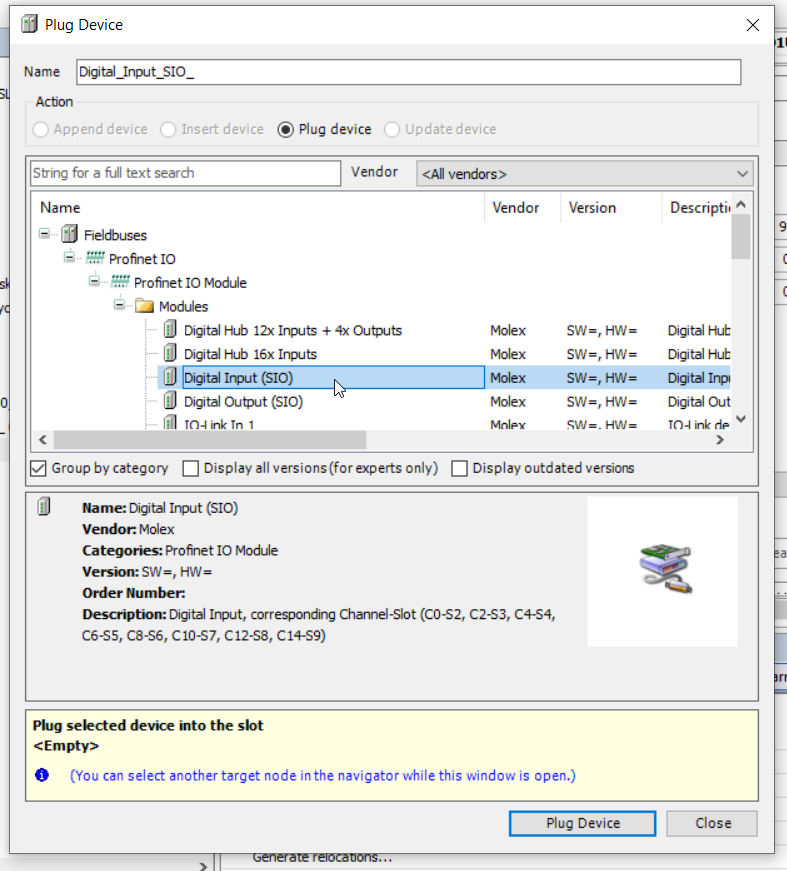
The configuration of Port1 with Normal Input is done.

Download your project and check if any error.
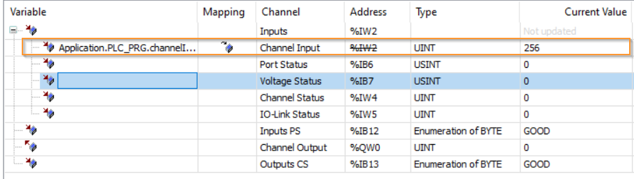
How to view
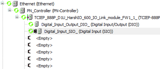
Please click the Digital_Input_Output_DIO object.

Channel Input will show the condition of each port.

Result
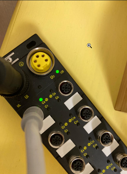
The LED status of TCIEP-888P-D1U Port1 is green and indicates this port is used as normal input .
Here is the result.
https://youtube.com/shorts/S3koWvoSMto
The value of Channel input is changed to 256.
Plug A IO Link Devices
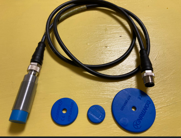
Let’s configure it with a IO-Link sensor.
Contrinex HF RFID system Read/Write modules RLS-1181-320 is used here.
Depending on the different type of IO-Link device, you need to check the manual for the device mapping.
Characters
Reference to the manual , the size of process input data is 9 bytes and output size is 10 bytes.

Process Data Input
For the process input mapping, the first byte is status information , from byte1 to byte 4 is the LSB of UID , byte 5-8 are the MSB of UID.

Add Slot
Now we know the specificity of this sensor, and I will connect the sensor to plot 4.
Select the 4th <empty> object , right click >Plug Device.

An IO-Link In/Out 16/16 object is Plugged into the master. although the process data in/out str 9bytes/10bytes, you only need to plug an object that is more than the specific:)

Done.

Rename
Rename a readable name of port4.
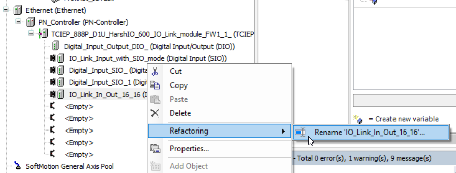
Let’s name it as RLS_1881_320.

If not connect..
If the IO-LINK Sensor is not connected, the ICON will be a red triangle.
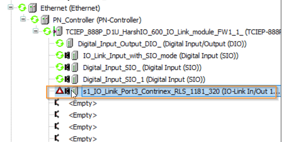
if connect
Conversely, if it is connected to the IO-LINK Sensor, ICON will turn green.

Result
When the Molex TCIE P-888P-D1U successfully connects to the IO-LINK Sensor, the LED will turn blue.
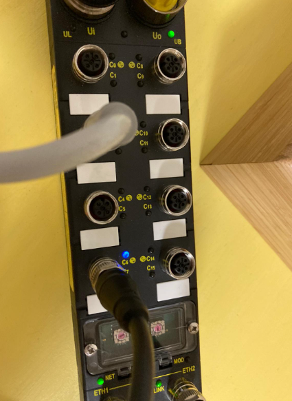
https://youtube.com/shorts/YPqHhiZXsV4
Try it!
Let’s actually read the RFID with that RFID Reader.
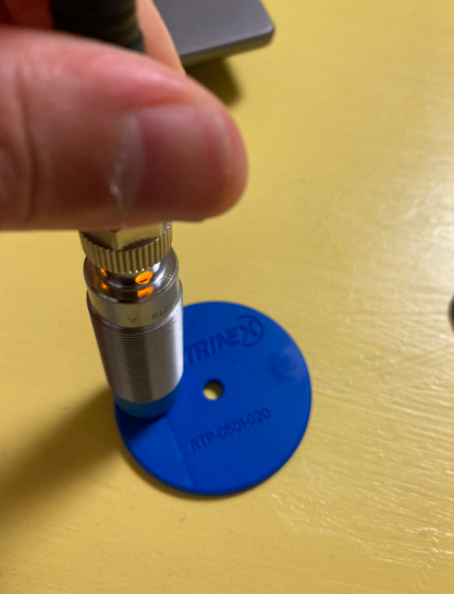
We get some values from the Data IN.
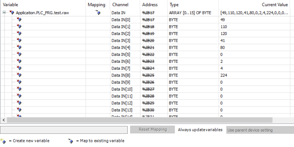
Implementation
If the operation check is OK, let’s create a program next.
DUT_Contrinex_RLS_1181_320_Byte0Status
This DUT defines each Bit in Byte0.
| TYPE DUT_Contrinex_RLS_1181_320_Byte0Status : STRUCT b00NBTag :BIT; //Number of Tags in front of RWM b01NBTag :BIT; //Number of Tags in front of RWM b02NBTag :BIT; //Number of Tags in front of RWM b03NBTag :BIT; //Number of Tags in front of RWM b04ANT :BIT; //0=RF Field OFF b05TAG :BIT; //0=No tag present in front of RWM b06,b07 :BIT; END_STRUCT END_TYPE |
DUT_Contrinex_RLS_1181_320
Then define it with the UID of Byte1-8.
| TYPE DUT_Contrinex_RLS_1181_320 : STRUCT Status :DUT_Contrinex_RLS_1181_320_Byte0Status; UID_LSB :DINT; UID_MSB :DINT; _ :ARRAY[0..6]OF BYTE; END_STRUCT END_TYPE |
uDUT_Contrinex_RLS_1181_320
Finally, define the UNION structure. The Byte array is assigned to Process Input.
| TYPE uDUT_Contrinex_RLS_1181_320 : UNION raw:ARRAY[0..15]OF BYTE; Data:DUT_Contrinex_RLS_1181_320; END_UNION END_TYPE |
FB_Contrinex_RLS_1181_320
The next step is to create a Function Block.
VAR
The variable Device is defined as uDUT_Contrinex_RLS_1181_320. The way to do this is to directly assign the Device in the Instance of the Function Block even if you increase the number of RFID Readers. In addition, Device data is output by Encoding Status / UID.
| FUNCTION_BLOCK FB_Contrinex_RLS_1181_320 VAR_INPUT END_VAR VAR_OUTPUT UIDLSB :DINT; UIDMSB :DINT; UID :LINT; TagsInfrontOFRWM :BYTE; TagOnRWM :BOOL; RFFieldON :BOOL; END_VAR VAR Device :uDUT_Contrinex_RLS_1181_320; END_VAR |
Program
| UIDLSB:=Device.Data.UID_LSB; UIDMSB:=Device.Data.UID_MSB; UID:=SHL(DINT_TO_LINT(Device.Data.UID_MSB),32); UID:=UID+Device.Data.UID_LSB; TagsInfrontOFRWM.0:=Device.Data.Status.b00NBTag; TagsInfrontOFRWM.1:=Device.Data.Status.b01NBTag; TagsInfrontOFRWM.2:=Device.Data.Status.b02NBTag; TagsInfrontOFRWM.3:=Device.Data.Status.b03NBTag; TagOnRWM:=Device.Data.Status.b05TAG; RFFieldON:=Device.Data.Status.b04ANT; |
Assign
Do not forget to assign the IOs.
Test
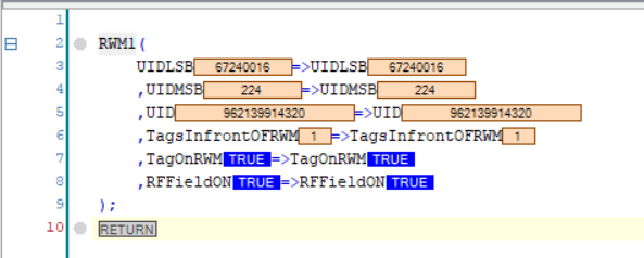
Test 1 reads the RFID Tag.
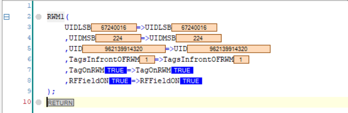
Test2
Test 2 reads another RFID Tag.
Test3
At the end, if you read 3 RFID Tags on top of each other, TagsInfrontOfRWM will be 3.

Sample Code
https://github.com/soup01Threes/Codesys/blob/main/Codesys_IOLINK_Pi3.projectarchive