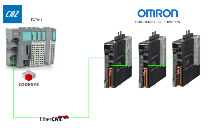
This time, we will connect the CMZ controller “FCT641” and the OMRON servo driver (R88D-1SN01L-ECT) in a 3-axis configuration using EtherCAT communication. We will introduce how to use “MC_GearInPos” to precisely synchronize the master axis and slave axis in a specific positional relationship.
This enables not only speed ratio control but also timing control where you can precisely align positions at specific points—this is the appeal of GearInPos.
Alright, let’s enjoy the FA.
Foreword
Thank you from the bottom of my heart for visiting my technical blog and YouTube channel.
We are currently running the “Takahashi Chris” radio show with Full-san (full@桜 八重 (@fulhause) / X) which I deliver every Wednesday night.
Sharing, not hoarding, technical knowledge
We publish technical information related to factory production technology and control systems for free, through blogs and videos.
With the belief that “knowledge should be accessible to everyone,” we share practical know-how and real-world troubleshooting cases from our own field experience.
The reason we keep it all free is simple: to help reduce the number of people who struggle because they simply didn’t know.
If you’ve ever thought:
- “Will this PLC and device combination actually work?”
- “I’m having trouble with EtherCAT communication—can someone test it?”
- “I want to try this remote I/O, but we don’t have the testing environment in-house…”
Feel free to reach out!If lending equipment or sharing your configuration is possible, we’re happy to verify it and share the results through articles and videos.
(We can keep company/product names anonymous if requested.)
How can you support us?
Currently, our activities are nearly all unpaid, but creating articles and videos takes time and a proper testing environment.If you’d like to support us in continuing and expanding this content, your kind help would mean a lot.
Membership (Support our radio show)
This support plan is designed to enhance radio with Mr Full.
https://note.com/fulhause/membership/join
Amazon Gift List (equipment & books for content production)
Lists equipment and books required for content creation.
https://www.amazon.co.jp/hz/wishlist/ls/H7W3RRD7C5QG?ref_=wl_share
Patreon (Support articles & video creation)
Your small monthly support will help to improve the environment for writing and verifying articles.
https://www.patreon.com/user?u=84249391
Paypal
A little help goes a long way.
https://paypal.me/soup01threes?country.x=JP&locale.x=ja_JP
Just trying to share things that could’ve helped someone—if only they’d known.
Your support helps make knowledge sharing more open and sustainable.
Thank you for being with us.
soup01threes*gmail.com
Technical knowledge shouldn’t be kept to ourselves.
Reference Link
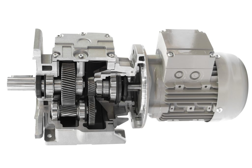
What is a gear reducer?
Simply put, it’s a device that reduces the motor’s rotational speed while increasing its torque. Motors excel at spinning rapidly, but in actual machinery (like conveyors and processing machines), we often need slow, powerful rotation. That’s where reducers come in—they lower the speed and increase the torque (force) accordingly.
Basic Terms
Terminology | Meaning |
|---|---|
Reduction ratio | Motor speed ÷ Output speed Example: 1000 rpm → 100 rpm is 10:1 |
Torque | Torque strength (Nm). Torque increases during deceleration. |
backlash | Backlash between gears is super important for precise control! |
Mechanism (Principle)
The gear reducer contains various gears inside.It converts the high-speed rotation on the input side (motor) into slow rotation on the output side (load).
MC_GearInPos
This function block (FB) synchronizes the master and slave axes in a specific positional relationship. Unlike the standard MC_GearIn, which links them based solely on the speed ratio, MC_GearInPos allows you to specify a position pair—essentially saying, “At this master position, the slave should be at this slave position.”
Caution
- MasterStartDistance must be negative or 0 to use in Buffered/Blending mode.
- Setting AvoidReversal=TRUE on a modulo (360° repeat) axis enables designs that prevent reversal.
- This assumes the master axis is already running via MC_MoveAbsolute or similar.
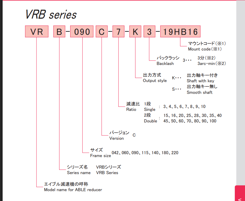
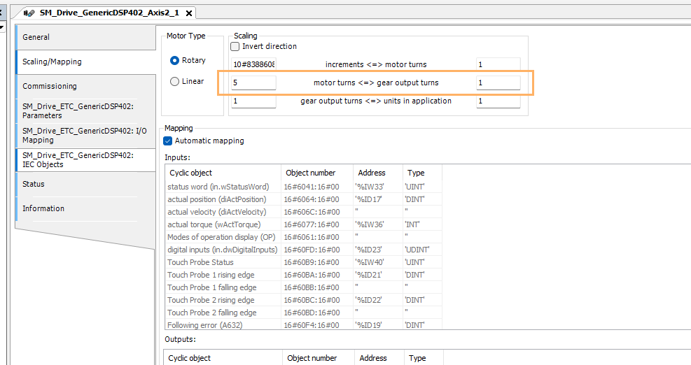
The model used this time is Nidec’s VRB-042C-5-K3-S8ZG8, so the reduction ratio is 5 for a single stage.
Interface
IN
Parameters | Meaning |
|---|---|
Execute | Processing starts on the rising edge |
RatioNumerator / Denominator | Gear ratio (e.g., 2:1) |
MasterSyncPosition | Synchronization is complete when the master axis reaches this position. |
SlaveSyncPosition | The slave shaft follows this position. |
MasterStartDistance | Distance to synchronization start point (equivalent to synchronization warning distance) |
BufferMode | Aborting/Buffered/BlendingPrevious |
AvoidReversal | If TRUE, slave reversal is not allowed (Modulo axis only) |
IN/OUT
Parameters | Meaning |
|---|---|
Master / Slave | Each Axis Reference (AXIS_REF_SM3) |
OUT
Parameters | Meaning |
|---|---|
StartSync | TRUE at the moment synchronization begins |
InSync | After synchronization is complete=TRUE |
Busy | Running flag |
Error / ErrorID | Error Occurrence Information |
CommandAborted | When interrupted by another FB = TRUE |
Specific Synchronization Operation Examples
This is an example of GearInPos synchronized operation.
- Master axis: Conveyor belt, moving at a constant speed
- Slave axis: Roller, starting perfectly synchronized at a fixed position to apply labels
-
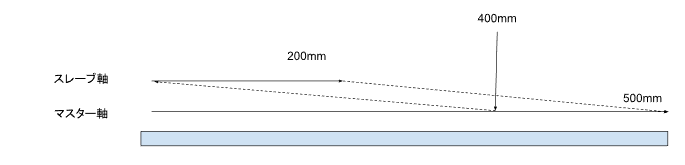
Requirement:
- When the master reaches position 500.0mm,
- I want to start synchronization around the master position 400.0mm
- so that the slave arrives precisely at position 200.0mm.

Therefore, shortening MasterStartDistance results in faster response, while lengthening it provides smoother synchronization. Additionally, setting Ratio to 1:2 creates a gear ratio where “the slave moves 1 unit for every 2 units the master moves.”
Parameter Settings
Parameter | Value | Unit | Explanation |
|---|---|---|---|
MasterSyncPosition | 500.0 | mm | A synchronization to be complete by the time the master reaches this position. |
SlaveSyncPosition | 200.0 | mm | If the slave is at this position when synchronization completes, it’s OK. |
MasterStartDistance | 100.0 | mm | In other words, synchronization begins at “500.0 – 100.0 = 400.0 mm” (including acceleration and deceleration). |
RatioNumerator | 1 | – | Speed ratio (1:1) |
RatioDenominator | 1 | – | |
BufferMode | MC_BUFFER_MODE.Aboring | – | |
AvoidReversal | FALSE | – | This time, it’s a general axis that doesn’t care about forward or reverse rotation. |
Timing
The actual movement of GearInPos based on time is as follows (please note that the time is a hypothetical setting).
timing | Action | signal |
|---|---|---|
t = 0 | マスターが走り始める(例:MC_MoveVelocity) | |
t = 1s | マスター位置 ≈ 400mm | MC_GearInPos.Execute := TRUE |
t = 1.2s | StartSync = TRUE(400mm通過時点) | |
t = 2.0s | マスターが500mm、スレーブも200mm到達 | InSync = TRUE (Perfectly synchronized!) |
Implementation Example
Axis_GearInPos(
|
|---|
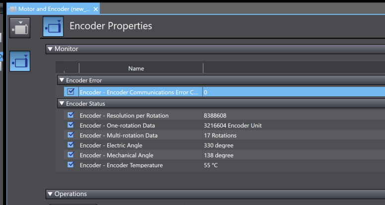
OMRONServo Encoder Screen
The OMRON R88 servo has an encoder properties screen, which contains those two items.
- Encoder Resolution per Rotation = 8388608, Number of pulses per rotation (theoretical value): Fixed at 8388608 (specification).
- One-rotation Data represents the data length per rotation unit currently mapped to the actual “0° to 360°” range.
Implementation
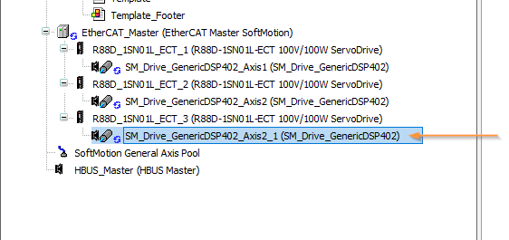
EtherCAT Configuration
This article adds a third OMRON servo. This servo is mounted on a gear reducer.
The gear reducer has a reduction ratio of 5:1, so please enter 5 in the Scaling/Mapping > Motor turns section.
Program
Next, we will create the program.
fbAxis
This is a continuation of the previous article. We declare the FB SM3_Basic.MC_MoveAbsolute for absolute positioning in fbAxis and connect it to AXIS_REF_SM3.
FUNCTION_BLOCK fbAxis
|
|---|
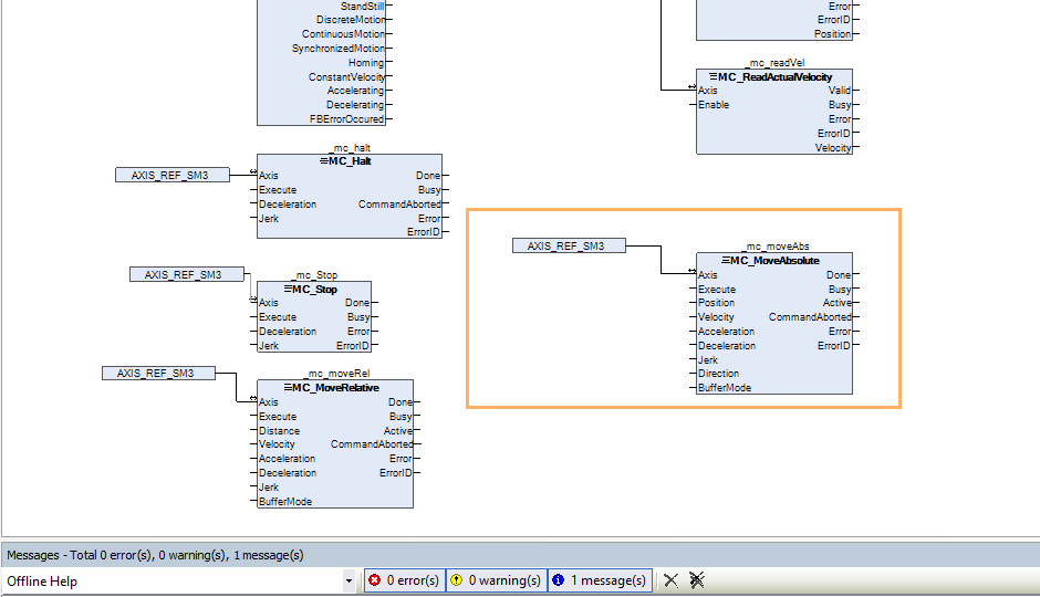
pAxis
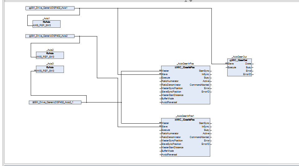
Next is pAxis. We’ll continue modifying the previous version. Add two FB blocks to SM3_Basic.MC_GearInPos and connect them to Axis 1 and Axis 2. In this article, the master axis will be Axis 3.
PROGRAM pAxis
|
|---|
screen
Next, we’ll modify the screen from the previous article.
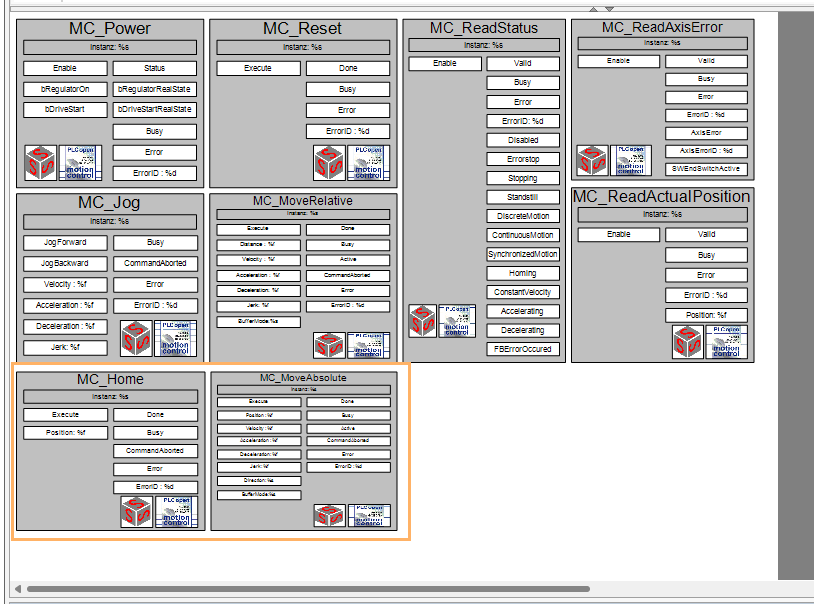
Visu-Template
Add MC_HOME and MC_MOVEAbsolute Template to the previous screen.Add MC_HOME and MC_MOVEAbsolute Template to the previous screen.
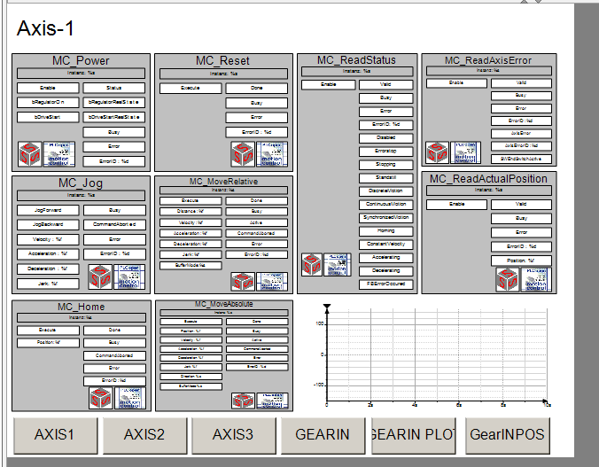
Visu-Axis1/2/3
Then modify the screen for each axis.
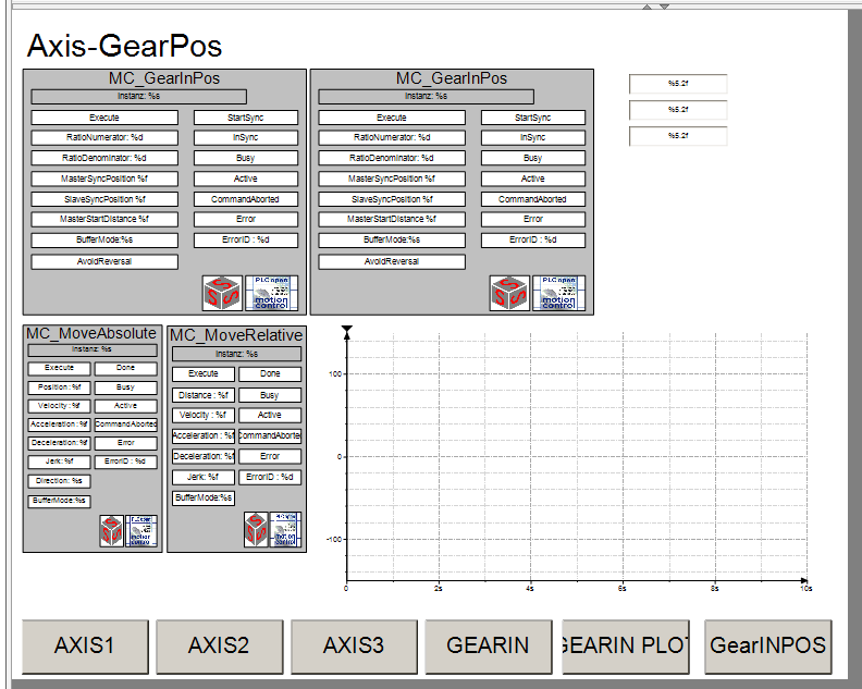
Visu-GearInPos
This is the GearInPos screen. We’ve added a GearInPos Template for synchronizing Axis 1 and Axis 2, and a Template for issuing absolute position commands. We’ve also enabled the trace to display the current values for all three axes.
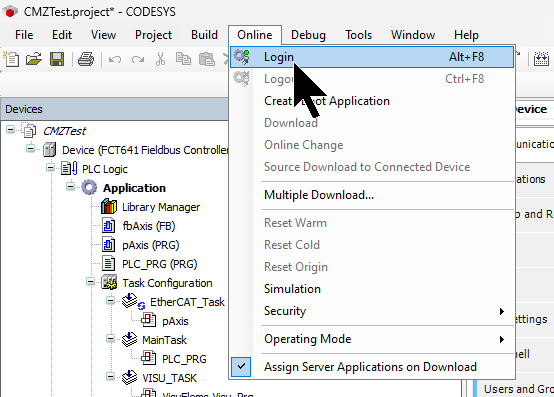
Log in to the device
From the menu: Online > Login, connect the device to the CODESYS IDE, and download the application.
Execution Start
Click the Play button (F5) to start the PLC application.

Result
You can verify the actual device’s operation by watching the demo video uploaded to YouTube.
Codesys.CMZ GearINPos FB with 3 OMRON EtherCAT Servo
Why did the master move to 150, but the slave stopped at 130?
This is because the “SlaveSyncPosition = 30.0” setting in MC_GearInPos is related to the gear ratio “1:1”.
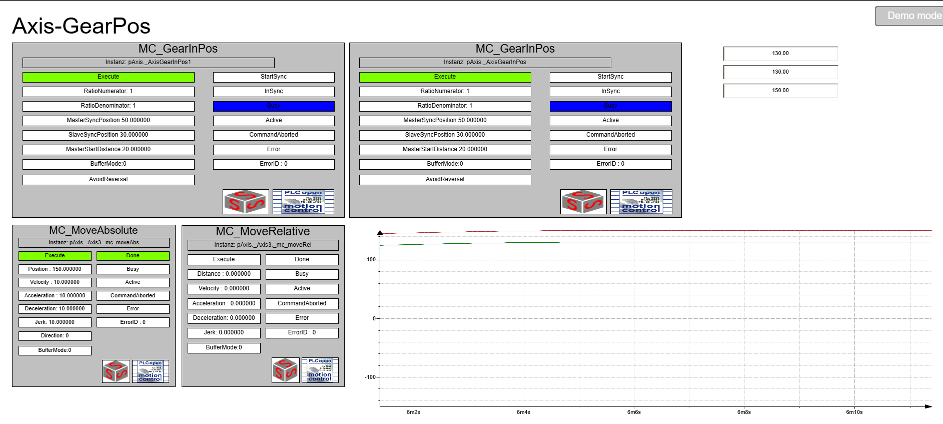
Comparing the current settings and results, when the master reaches 50.0, the slave reaches 30.0.
Item | Value | Explanation |
|---|---|---|
RatioNumerator | 1 | Gear ratio: 1 |
RatioDenominator | 1 | (1:1) |
MasterSyncPosition | 50.0 | Synchronization completes at this point. |
SlaveSyncPosition | 30.0 | Control the slave so that it is at this position when synchronization is complete. |
The gear ratio is 1:1, so “if the master moves 100, the slave also moves 100.” But since the slave was at “30.0” at the start…
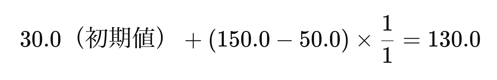
Slave position = SlaveSyncPosition + (Master movement amount − MasterSyncPosition)→ Therefore, 30.0 + (150.0 − 50.0) = 130.0.
To put it simply, the control system uses the position pair at synchronization completion as the “reference point,” then carries over subsequent movement based on the gear ratio. The ultimate goal is not “150:130,” but movement based on “50:30” as the reference, with increments from there following the gear ratio.
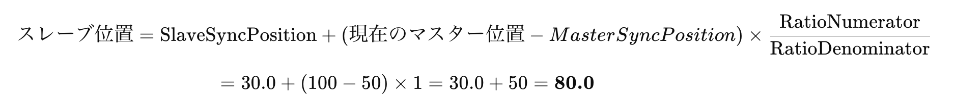
When the master axis is positioned from 150 to 100, what happens to the slave axis?
Now, let’s take another look at the settings. When the master reaches 50, the slave is at 30. Using this as the reference point, they will move together according to the gear ratio from this point onward.
Item | Value |
|---|---|
MasterSyncPosition | 50.0 |
SlaveSyncPosition | 30.0 |
Ratio | 1:1(=1) |
As a result, the slave also operates to return to “80.0”.
Does that mean MasterStartDistance becomes irrelevant at that point?
To put it simply, once synchronization (InSync) is established, MasterStartDistance becomes irrelevant. To summarize from the table:
Timeing | MasterStartDistance’s role |
|---|---|
Before the start of the same period | The distance that determines where to accelerate or decelerate to achieve synchronization. In other words, the preparation section. |
Commencing simultaneously | When the master passes MasterSyncPosition – MasterStartDistance, StartSync becomes TRUE, and the slave begins to chase. |
InSync = TRUE (Synchronization complete) onwards | Irrelevant! → From this point on, it will follow the master solely based on the gear ratio (purely a follow state). |
For example, with the current settings…
- MasterSyncPosition = 50.0
- MasterStartDistance = 20.0
In other words, the slave’s synchronized operation begins when the master reaches 30.0, and InSync = TRUE when it reaches 50.0.
After that, even if the master moves from 150.0 back to 100.0, the slave simply follows that movement perfectly at the gear ratio, and MasterStartDistance is no longer used.