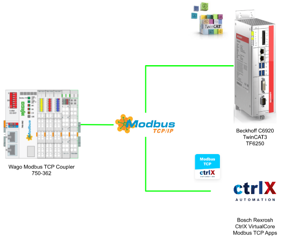
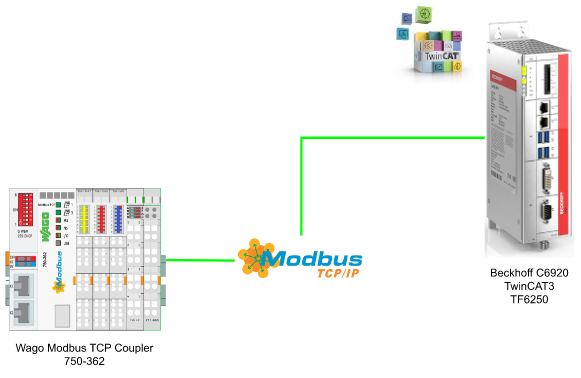
In this post, I will explain how to use Beckhoff C6920 TwinCAT TF6250 Functions / ctrlX Virtual Core to access the Wago 750-362 Modbus TCP Coupler Step by Step.Hope you like this.
Thanks!
Because of Beckhoff Japan and Wago Japan that lend the devices to me – I can create this post.
Beckhoff Japan
IPC6920-005 was lent by Beckhoff Japan, a Japanese subsidiary of Beckhoff. Founded in 1980, Beckhoff Automation is a German company at the forefront of the introduction of open automation systems based on PC-based control technology.
Beckhoff Japan Corporation Beckhoff Automation Co., Ltd. established its head office in Yokohama in 2011 and the Nagoya office in 2017.

Here is the Home page of Beckhoff Japan.
https://www.beckhoff.com/ja-jp/
Wago Japan
750-362 ModbusTCP Coupler is lent by Wago Japan Co., Ltd. WAGO was started in 1951, a German company that has supported the field with the technologies of PUSH WIRE and CAGE CLAMP, and have contributed to industries around the world with terminal block technology. WAGO also has a PLC LINEUP, offering automation solutions with an emphasis on openness and flexibility.
Wago Japan Co., Ltd. is headquartered in Koto-ku, Tokyo.

Wago Side
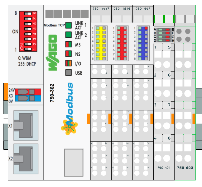
This is the 750-362 Modbus TCP Coupler that we used in this tutorial.
750-1417 is a 8 channel Digital Input,750-1516 is a 8 channel Digital Output, 750-597 is an 8 channel analog output module, and 750-471 is a 4 channel analog input channel.
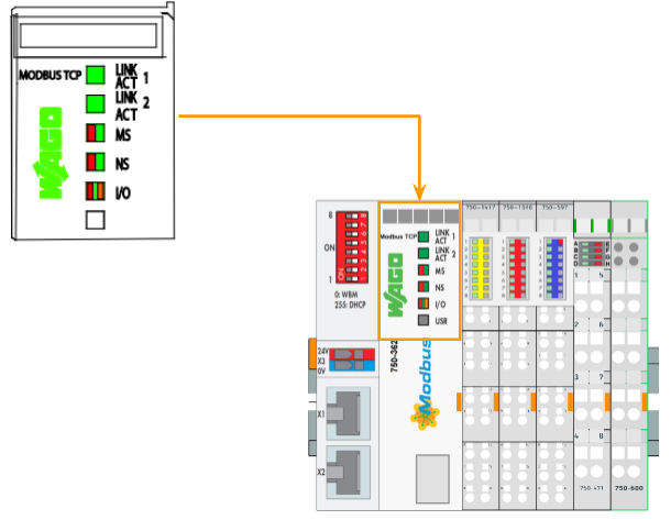
LED
There are 5 LEDs that indicate the current status of your Coupler.Please reference the manual to get more information.
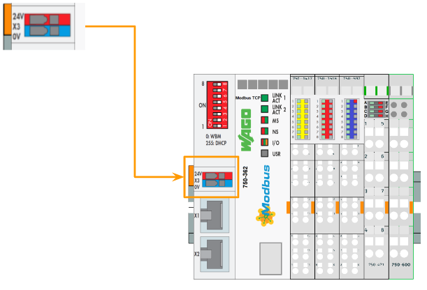
Power Supply
Here is the Power Supply.
Example
Here is an Example to show you the MODBUS function that can be used to access the data.
Operation System
After the Master configuration is done,and we turn on the power or Reset, the system starts to operate.The 750-362 Coupler begins running up and it will determines the I/O modules and configuration is correct or not – the “I/O’ LED is blinking red in that time.
If the Coupler change the state to “Fieldbus Start” Mode, the ‘I/O’ led will light up green.
If that is any event of a failure, the ‘I/O’ LED will blinking red.

Process Data
In the Basic structure, the fieldbus coupler will identify all I/O Modules that are connected and send/receive the data.
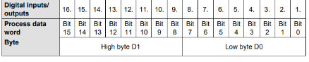
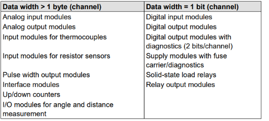
The Digital I/O modules are bit-oriented, meaning that the digital data are sent bit by bit.
The Analog I/O modules are sent the data byte by byte and sent the data with a “Group”.This group includes counter modules/Distance measurement modules..etc.
For the Process Data , there are 2 types – PII(Process Input Data) and PIO(Process Output Data).And these Input,Output process image data are stored in a sequence that depends on its physical position.
(If a Digital I/O Information exceeds 8 bits, the coupler will start a new byte.)
Data Exchange
750-362 is a fieldbus coupler that exchanges the data via Modbus TCP or Modbus UDP – Modbus TCP is used in my tutorial and it works as a Master/Slave principle.
The master can be PLC or PC(in our case, it is TwinCAT TF6250 and CtrlX Modbus App)
Here is the specification for the simultaneous connections(Socket connects):
- 3 connections for HTTP(s), The HTML pages from the coupler.
- 15 connections via Modbus TCP
- 10 Connections for FTP.
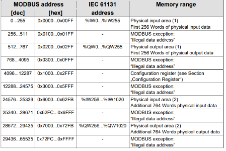
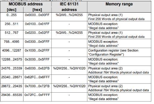
Memory Space
For any wago fieldbus coupler, process image contains all the physical data.
The range is 0..255 and word 512..1275.
- The input module data can be read by the CPU/Fieldbus Side.
- The output module data can be written from CPU/Fieldbus SIde.

There are 4 different types of process data in the controller:
- Input words
- Output words
- Input bits
- Output bits
IP addressing
There are 4 methods for you to assign the IP address to the fieldbus Coupler.
- using DIP Switch(Manually)
- using DHCP
- using “WAGO Ethernet Setting”, a serial communication port or Ethernet port
- using BootP
DIP
by using DIP Switch, we can configure the last byte of the IP Address between 1 to 254.For Example, if we set the DIP switch value with a binary code 00110010(50), the IP address of your Coupler is 192.168.1.50.
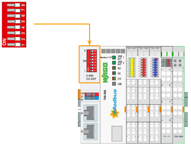
Here is the DIP Switch Setting Range:
- 1..254, the IP address is from 192.168.1.1 to 192.168.1.254.
- 0,DHCP,BooP,Static can be used.
- 255,DHCP can be used.
Commissioning
DIP Switch
In this tutorial, we will set all DIP as 1 to configure the Coupler via DHCP.
To prevent network trouble,you need to confirm that only ONE DHCP server exists in your network, and the DHCP assigned IP address is only temporarily valid.Please use the static address configuration in your real application.

Web server
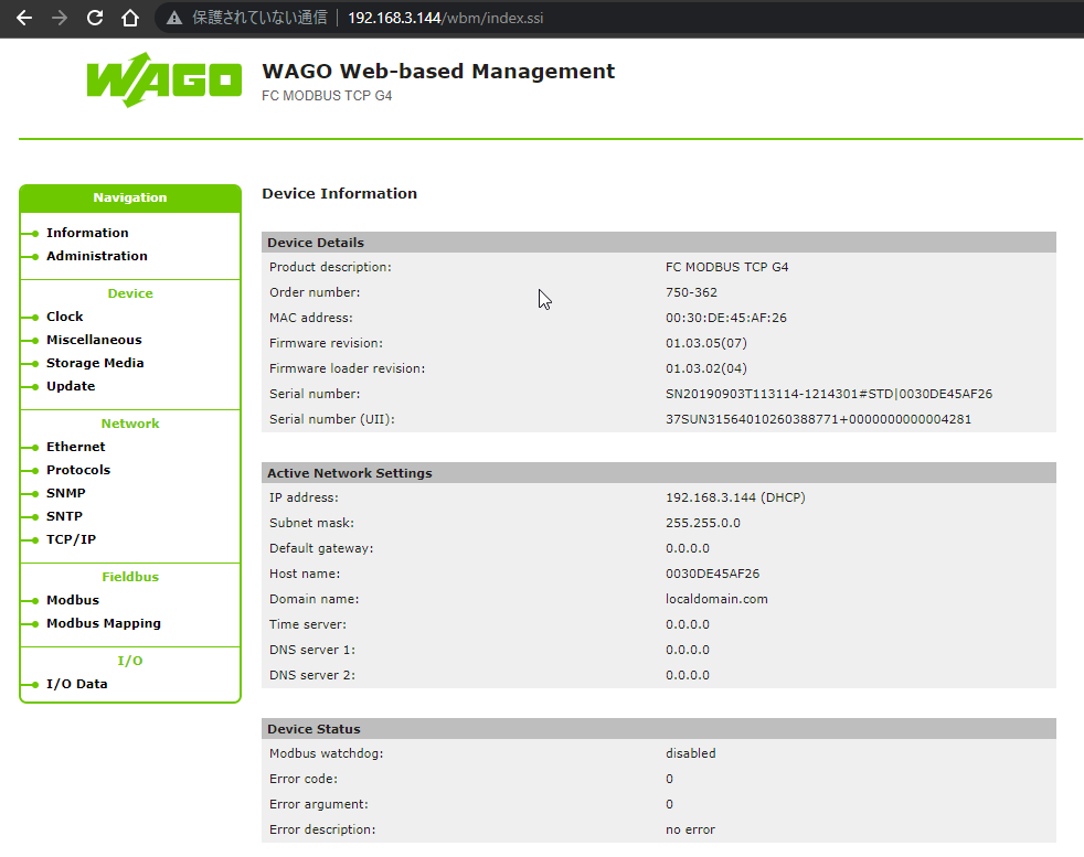
Access the server
Enter the IP address of your 750-362 modbus Coupler to access the WBM.
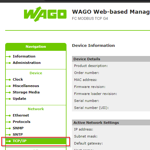
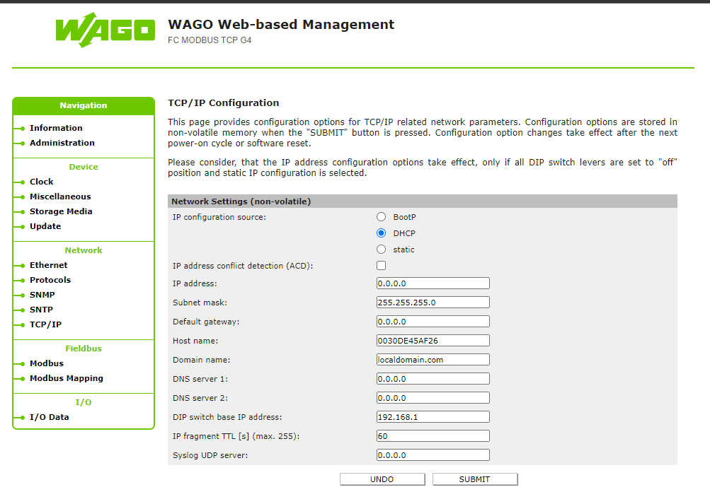
TCP/IP
Open the TCP/IP Settings.
A login operation is requested, for default,
- user=admin,password=wago
- user=user,password=user
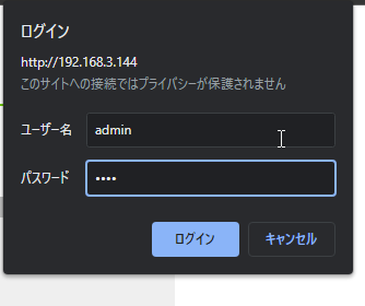
In this page, we can configure your coupler as a static ip also.
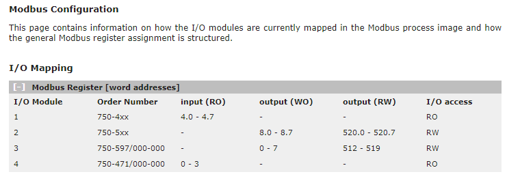
Mapping
Go to Fieldbus>Modbus Mapping, A I/O Mapping screen is shown.
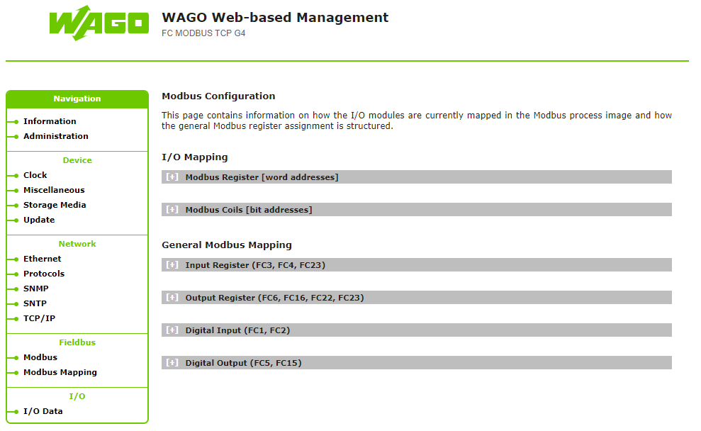
in this screen , you can confirm the address for each sub-slot.
Modbus
There are some Function Code in the Modbus communication.
Function Code
FC2(Read Discrete Inputs)
A Function to read the input bits from Modbus Slave devices, and the request specifies the starting address(Register Number) and the bit count to be read.
FC3(Read Multiple Registers)
A Function to read the holding register from Modbus Slave devices in Word Format, and the request specifies the starting address(Register) and the word count to be read.
FC4(Read Input Registers)
A function to read the input registers from the Modbus slave devices in word format, and the Request specifies the starting address(Register) and the word count to be read.
FC5(Write Coil)
A function to write the coil from the Modbus slave devices in bit format, and the Request specifies the starting address(Coil Address) and the bit count to be written.
FC6(Write Single Register)
A function to write a Single Register from the Modbus slave devices in word format, and the Request specifies the starting address(Register Address).
FC11(Get Comm Event Counter)
A function that returns a status word and the event counter from the Modbus slave devices.
FC15(Write Multiple Coils)
A Function to write a sequence of output coils 1 or 0 in the Modbus Slave devices(Maximum number is 256 bits), and the Request specifies the first Coil number in your sequence and the bit counter that you would like to write.
FC16(Write Multiple Registers)
A Function to write a sequence of Register in the Modbus Slave devices, and the Request specifies the first register of address and the word count that you would like to write.
FC22(Mask Write Register)
A Function to manipulate couples bits with a register by using a AND Mask or Or Mask.
FC23(Read/Write Multiple Registers)
A Function that performs a combination of read/write in a single request
Mapping
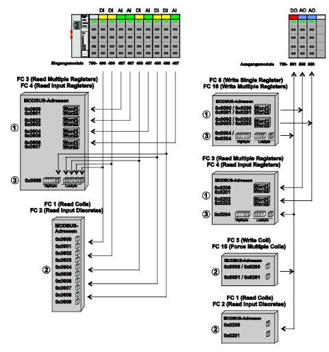
FC3/FC4
Here is Register Access Reading with FC3 and FC4.
FC6/FC16
Here is Register Access Reading with FC6 and FC16.
FC1/FC2
Here is the mapping of Bit Access Reading FC1/FC2.

FC5/FC15
Here is the Mapping of Bit Access Writing with FC5/FC15.

Implementation-1 with TwinCAT
In this Implementation, I will show you how to use Beckhoff TwinCAT3 TF6250 Modbus TCP Function Block to access the Wago 750-362 Modbus TCP Coupler.
Reference Link
Config
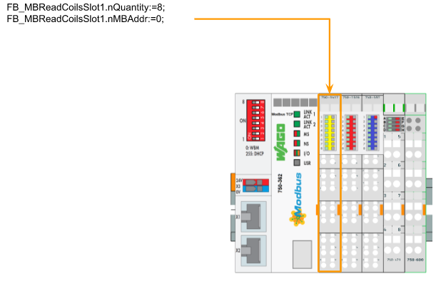
Slot1 750-1417
For slot1, we will configure the Modbus function parameter nQuantity=8, and nMBAddr=0 with a FB_MBReadCoils Function Block.
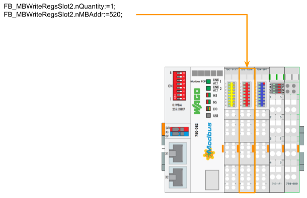
Slot2 750-1516
For slot2, we will configure the Modbus function parameter nQuantity=1, and nMBAddr=520 with a FB_MBReadRegs Function Block.
Slot3 750-597
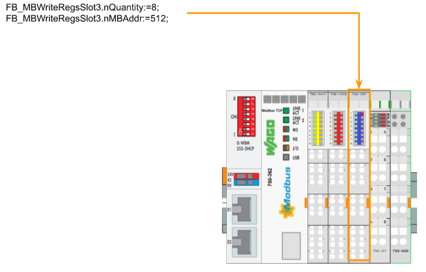
For slot3, we will configure the Modbus function parameter nQuantity=8, and nMBAddr=512 with a FB_MBReadRegs Function Block.
Slot4 750-471
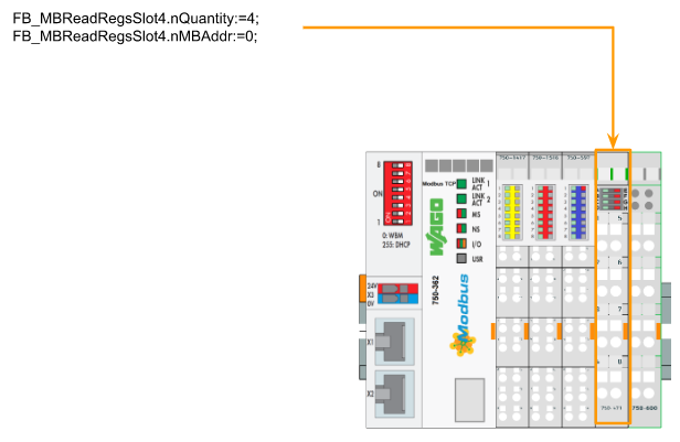
For slot4, we will configure the Modbus function parameter nQuantity=4, and nMBAddr=0 with a FB_MBReadRegs Function Block.
PLC Side
Here is the PLC program.
VAR
| PROGRAM MAIN VAR iStep :INT; bStart :BOOL; bReset :BOOL; bSlotAutoReflash :BOOL; END_VAR VAR FB_MBReadCoilsSlot1 :FB_MBReadCoils; FB_MBWriteRegsSlot2 :FB_MBWriteRegs; FB_MBWriteRegsSlot3 :FB_MBWriteRegs; FB_MBReadRegsSlot4 :FB_MBReadRegs; WagoSlot1 :BYTE; WagoSlot2 :INT; WagoSlot3 :ARRAY[0..7]OF INT; WagoSlot4 :ARRAY[0..3]OF INT; F_TRIG_Slots :ARRAY[1..4]OF F_TRIG; TONs :ARRAY[0..3] OF ton; END_VAR VAR CONSTANT sIPAddr :STRING:=’192.168.3.144′; nTCPPort :UINT:=502; END_VAR |
PROGRAM
We use read the Digital Input Module in Slot1(750-1417)>write the Digital Output Module(750-1516)>write the Analog Output Module (750-597)>Finally read the Analog input module(750-471)>Loop Back.
| IF bSlotAutoReflash THEN TONs[0](IN:=WagoSlot2=0,PT:=T#1S); TONs[1](IN:=WagoSlot2=16#FF,PT:=T#1S); IF TONs[0].Q THEN WagoSlot2:=16#FF; WagoSlot3[4]:=WagoSlot3[4]+16#100; END_IF IF TONs[1].Q THEN WagoSlot2:=16#00; END_IF IF WagoSlot3[4] >=16#7500 THEN WagoSlot3[4]:=16#00; END_IF END_IF; CASE iStep OF 0: IF bStart THEN iStep:=10; bStart:=FALSE; bReset:=FALSE; END_IF 10: FB_MBReadCoilsSlot1.nTCPPort:=nTCPPort; FB_MBReadCoilsSlot1.nUnitID:=1; FB_MBReadCoilsSlot1.nQuantity:=8; FB_MBReadCoilsSlot1.sIPAddr:=sIPAddr; FB_MBReadCoilsSlot1(bExecute:=FALSE); FB_MBReadCoilsSlot1.cbLength:=SIZEOF(WagoSlot1); FB_MBReadCoilsSlot1.pDestAddr:=ADR(WagoSlot1); FB_MBReadCoilsSlot1.nMBAddr:=0; FB_MBWriteRegsSlot2.nTCPPort:=nTCPPort; FB_MBWriteRegsSlot2.nUnitID:=1; FB_MBWriteRegsSlot2.nQuantity:=1; FB_MBWriteRegsSlot2.sIPAddr:=sIPAddr; FB_MBWriteRegsSlot2(bExecute:=FALSE); FB_MBWriteRegsSlot2.cbLength:=SIZEOF(WagoSlot2); FB_MBWriteRegsSlot2.pSrcAddr:=ADR(WagoSlot2); FB_MBWriteRegsSlot2.nMBAddr:=520; FB_MBWriteRegsSlot3.nTCPPort:=nTCPPort; FB_MBWriteRegsSlot3.nUnitID:=1; FB_MBWriteRegsSlot3.nQuantity:=8; FB_MBWriteRegsSlot3.sIPAddr:=sIPAddr; FB_MBWriteRegsSlot3(bExecute:=FALSE); FB_MBWriteRegsSlot3.cbLength:=SIZEOF(WagoSlot3); FB_MBWriteRegsSlot3.pSrcAddr:=ADR(WagoSlot3); FB_MBWriteRegsSlot3.nMBAddr:=512; FB_MBReadRegsSlot4.nTCPPort:=nTCPPort; FB_MBReadRegsSlot4.nUnitID:=1; FB_MBReadRegsSlot4.nQuantity:=4; FB_MBReadRegsSlot4.sIPAddr:=sIPAddr; FB_MBReadRegsSlot4(bExecute:=FALSE); FB_MBReadRegsSlot4.cbLength:=SIZEOF(WagoSlot4); FB_MBReadRegsSlot4.pDestAddr:=ADR(WagoSlot4); FB_MBReadRegsSlot4.nMBAddr:=0; IF NOT FB_MBReadCoilsSlot1.bBusy AND NOT FB_MBWriteRegsSlot2.bBusy AND NOT FB_MBWriteRegsSlot3.bBusy AND NOT FB_MBReadRegsSlot4.bBusy THEN iStep:=20; END_IF 20: FB_MBReadCoilsSlot1(bExecute:=TRUE); F_TRIG_Slots[1](CLK:=FB_MBReadCoilsSlot1.bBusy); IF F_TRIG_Slots[1].Q AND NOT FB_MBReadCoilsSlot1.bError THEN iStep:=30; END_IF IF FB_MBReadCoilsSlot1.bError THEN iStep:=999; END_IF 30: FB_MBWriteRegsSlot2(bExecute:=TRUE); F_TRIG_Slots[2](CLK:=FB_MBWriteRegsSlot2.bBusy); IF F_TRIG_Slots[2].Q AND NOT FB_MBWriteRegsSlot2.bError THEN iStep:=40; END_IF IF FB_MBWriteRegsSlot2.bError THEN iStep:=999; END_IF 40: FB_MBWriteRegsSlot3(bExecute:=TRUE); F_TRIG_Slots[3](CLK:=FB_MBWriteRegsSlot3.bBusy); IF F_TRIG_Slots[3].Q AND NOT FB_MBWriteRegsSlot3.bError THEN iStep:=50; END_IF IF FB_MBWriteRegsSlot3.bError THEN iStep:=999; END_IF 50: FB_MBReadRegsSlot4(bExecute:=TRUE); F_TRIG_Slots[4](CLK:=FB_MBReadRegsSlot4.bBusy); IF F_TRIG_Slots[4].Q AND NOT FB_MBReadRegsSlot4.bError THEN iStep:=10; END_IF IF FB_MBReadRegsSlot4.bError THEN iStep:=999; END_IF 999: IF bReset THEN iStep:=10; bReset:=FALSE; END_IF END_CASE |
Visualization
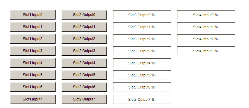
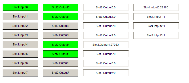
Here is a simple HMI Display to show the current value of each slot, and you can change the value of the output module here.
Result
you can see the result from this video link:
Source Code
Please download the Source Code from this Link:
https://github.com/soup01Threes/TwinCAT3/blob/main/Wago750_362_TwinCAT%20Project_ModbusTCP.tnzip
Implementation-2 with Ctrlx
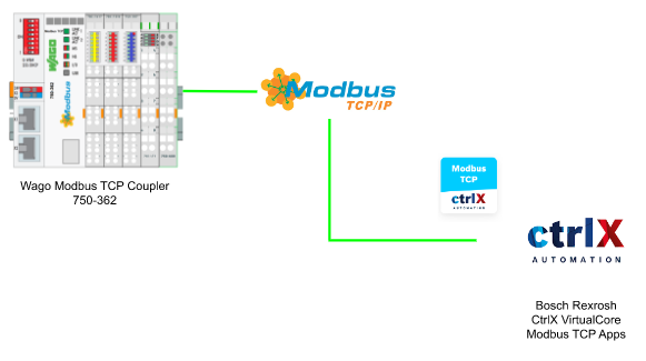
In this Implementation, I will show you how to use the ctrlX Virtual Core with their Modbus TCP/IP Apps to establish the connection with Wago Modbus TCP Coupler 750-362.
Reference Link


MODBUS TCP APP?
As we know, Modbus is a very common communication protocol in Factory automation that enables the data to be exchanged from master and multiple slaves – and all Data are sent in TCP/IP packages.
This Modbus TCP App allow ctrlx CORE to connect with other Modbus-TCP Slave Devices(in my case it is Wago) and then passing these data to your PLC runtime via real-time data layer.
By using Modbus TCP App,you can:
- Communication with Modbus Network
- Configuration of the modus device
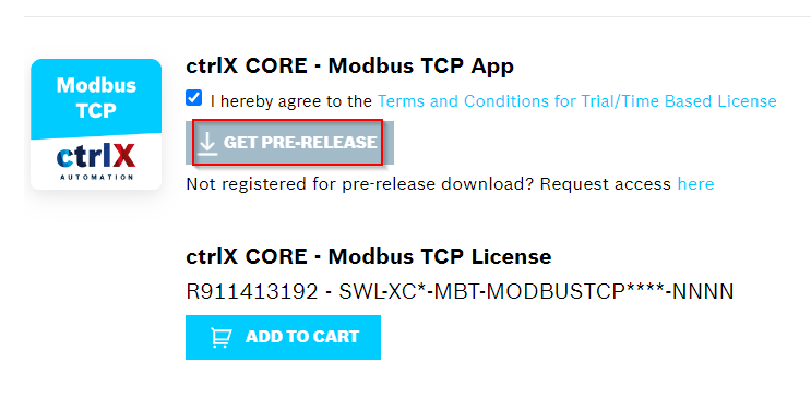
Modbus TCP App Installation
Please access this link to download the latest version of Modbus TCP App.
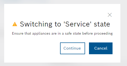
Change your runtime to Service Mode.
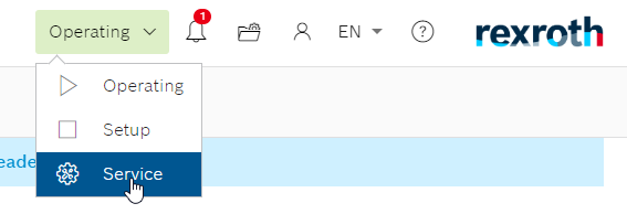
Press Continue.
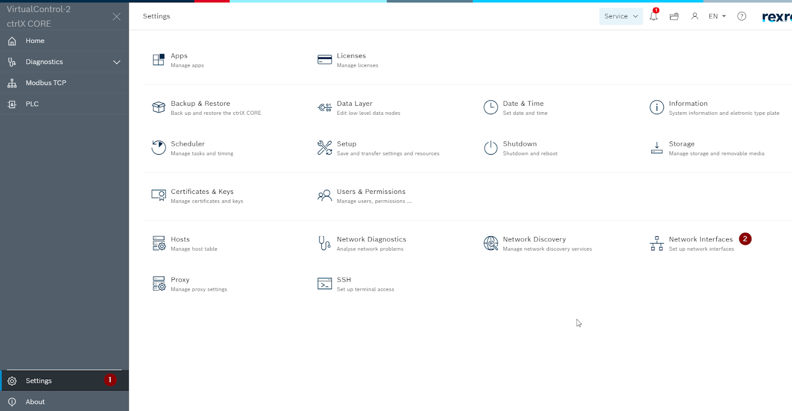
Go to Settings>Apps.

Press Install from Files to install your Modbus TCP App.


Install it!

Please wait a mins..

Done!

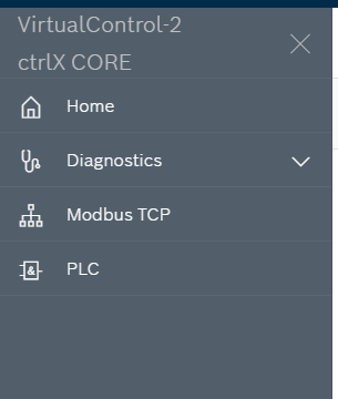
Now you can also see a Modbus TCP item is added in your slide menu.
Port Configuration
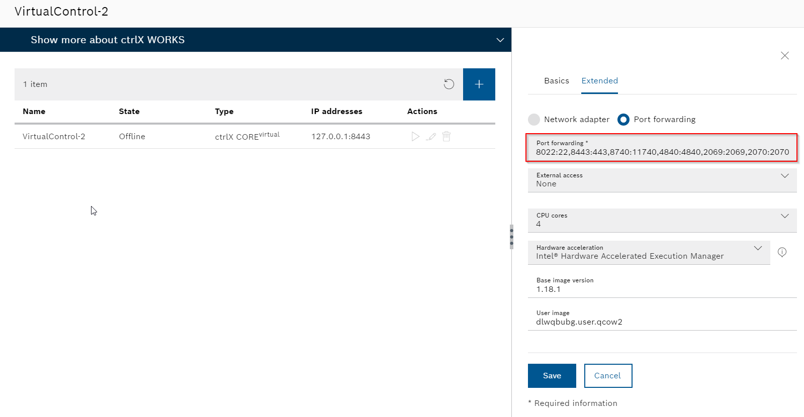
Because Virtual Core is running in a virtual environment, a Port Forwarding setting is necessary. Go to Extended tab>.Configure the network as Port forwarding
Here is the Port forward setting in my virtual core:
8022:22,8443:443,8740:11740,4840:4840,2069:2069,2070:2070
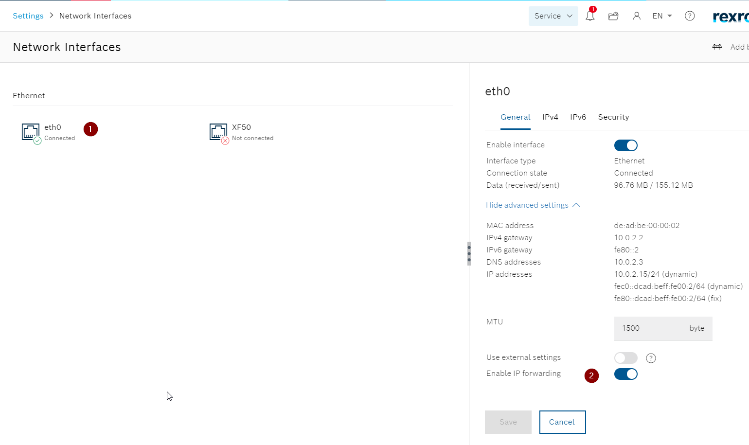
Open your Virtual Core WBM, go to setting>Network Interface.
Choose eth0 and enable the Port Enabling operation.
Connection Test
Because we configured the connection to Wago 750-362 Coupler, i will use the PFC200 controller with a Modbus-TCP Server built last time.
Reference Link
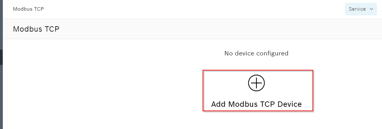
Configure the Modbus TCP Devices
Click the “Add Modbus TCP Device” to insert a Modbus TCP slave device.
A Add Device is shown in here.
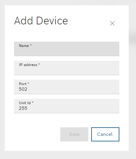
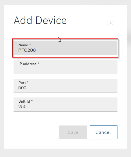
Name
It is a field for your modbus slave name.In my case, PFC200 is sued.
IP Address
Here is a field to configure the ip address of your Modbus Slave.
In my case, 192.168.3.17 is used.

Port
The port number of your Modbus Slave Devices.
By Default, 502 is used in modbus TCP.

Unit Id
Here is a unit ID, just keep in default.

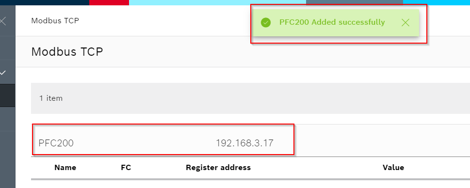
After you press the save button, a new modbus tcp slave device is inserted!
Add Modbus TCP Register
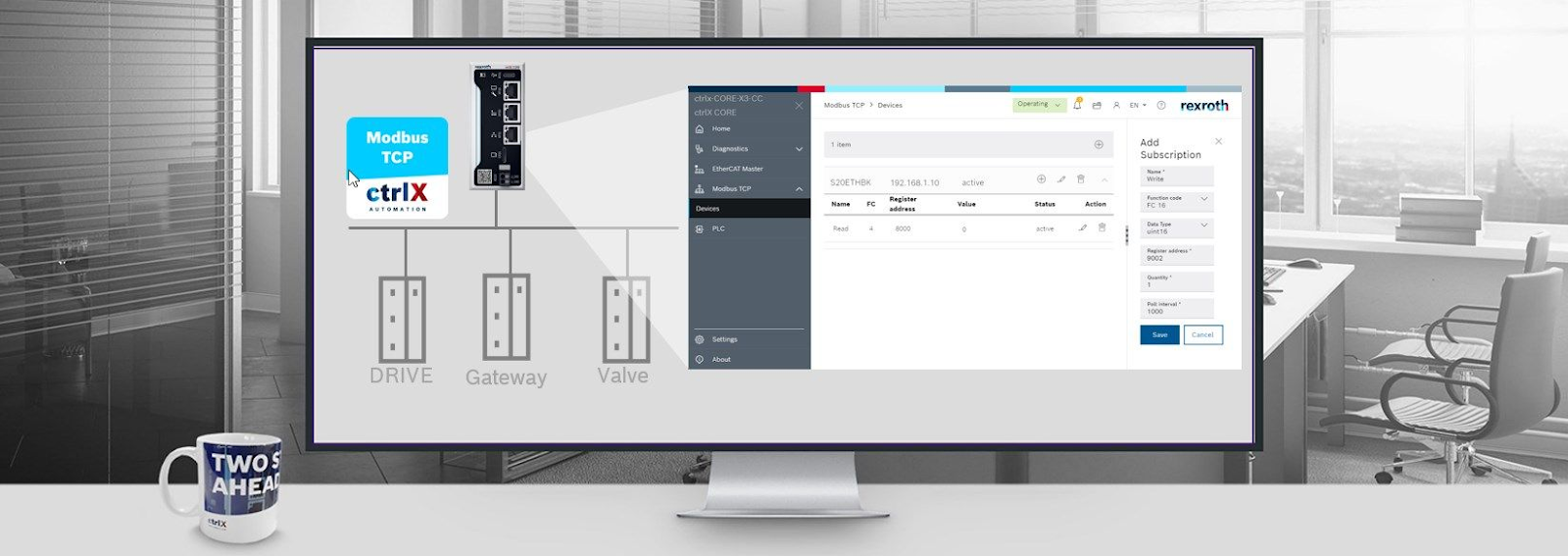
Now we can add some Register for us to access, please press the + button.
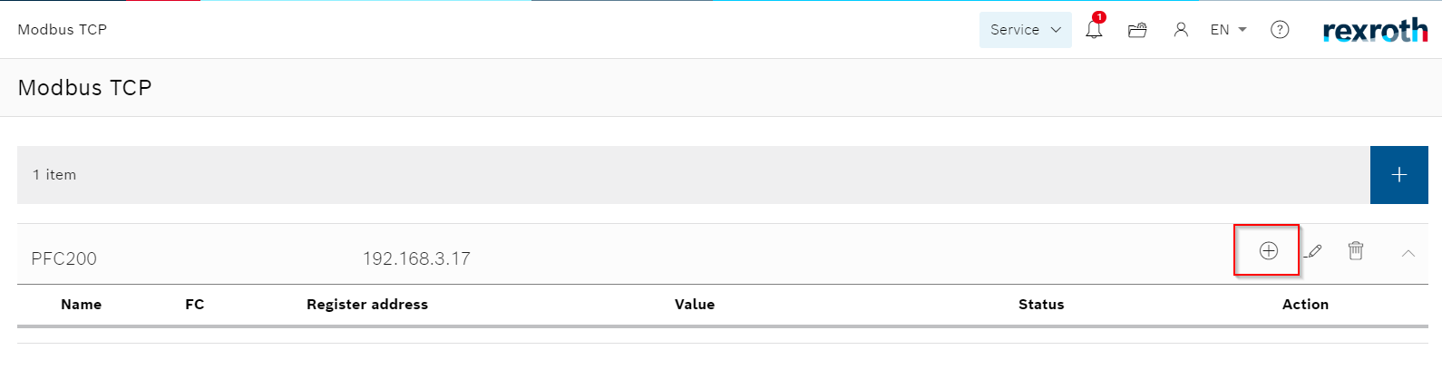
A Subscription screen is shown.

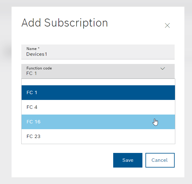
Name
Here is the Name field of the Subscription.in My case, Devices1 is used.

Function Code
Here is the Function Code of this subscription.Only FC1/FC4/FC16/FC23 can be used.
Register Configuration
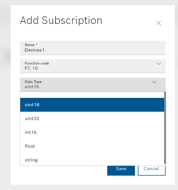
In my case,FC16 is used and you need to configure something about the register.

Data Type
Here is the field for you to set up the data type of this subscription.

uint16/uint32/int16/float/string can be used.
Register address
Here is the starting register of your subscription.
Now we will use FC16, as a uint16 Data type with starting Register address 32008.

Quantity
Here is a Field that shows how much data you need to operate, in my case, Quantity=1.
Now we will use FC16, as a uint16 Data type with starting Register address 32008,1 Register.
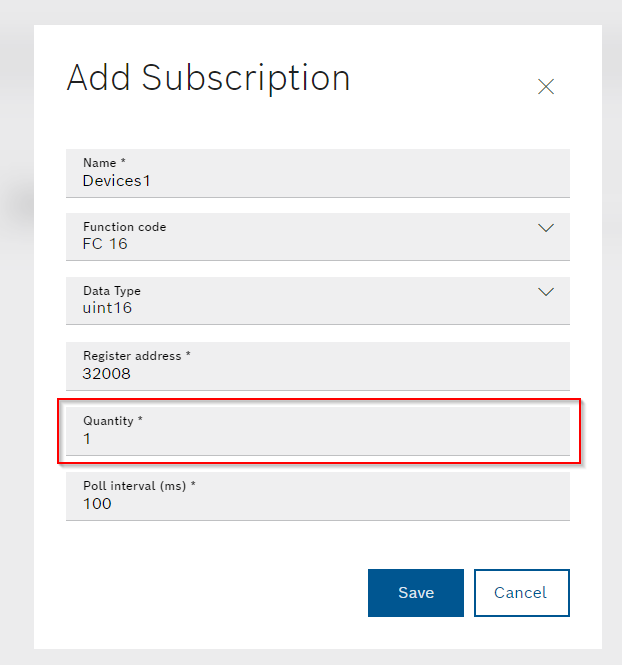
Poll interal(ms)
The polling time – you can imagine it is the cycle time to refresh your data.
Now we will use FC16, as a uint16 Data type with starting Register address 32008,1 Register in 100ms.

Press save button to apply the setting – If your connection is OK, the status is changed to “active”.

Do the same configuration with FC4/FC16 to access the same register.
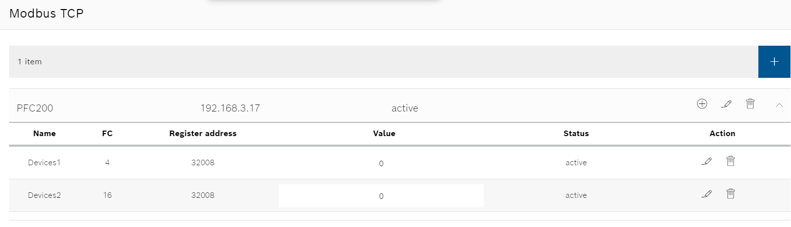
Result
We can direct enter the value with FC16 field, and you can see the value is immediately
update with FC4 field, we did it!
Connect to 750-362 Wago Coupler
Now we can configure the modbus tcp connection with Wago Coupler 750-362.
Apps Side
Here is the Configuration and I will explain it step by step.
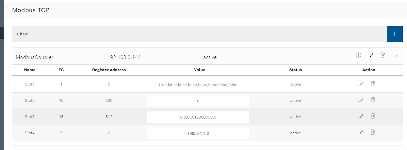
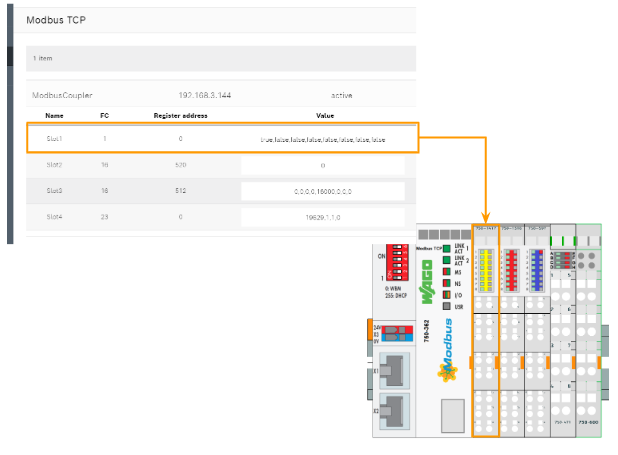
Slot1 750-1417
For Slot1 750-1417 8 channel Digital Input, we will use FC1, start Register address as 0 and Quantity 8 , to read 8 coils from address 0.
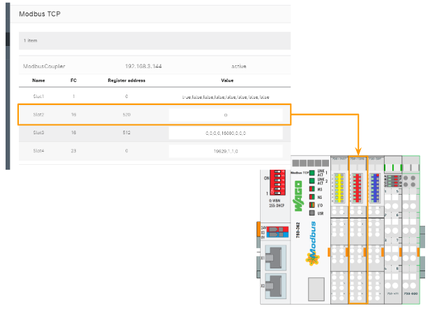
Slot2 750-1516
For Slot2 750-1516 8 channel Digital Output, we will use FC16, start Register address as 520 and Quantity 1, to write 1 Register from address 520.
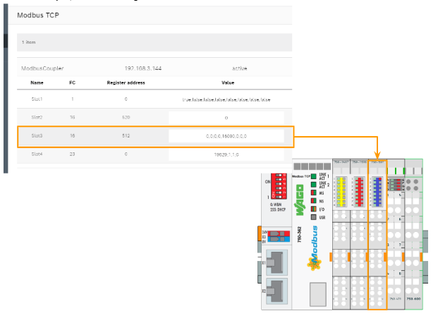
Slot3 750-597
For Slot3 750-597 8 channel Analog Output, we will use FC16, start Register address as 512 and Quantity 8, to write 8 Register from address 512 to 519.
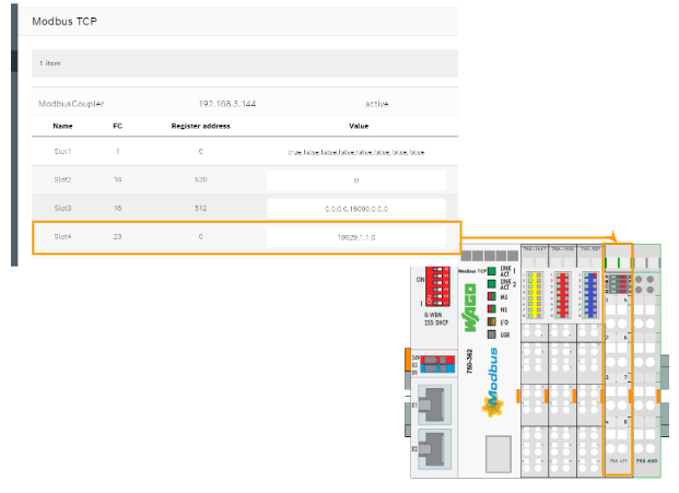
Slot4 750-471
For Slot4 750-471 4 channel Analog Input, we will use FC23, start Register address as 0 and Quantity 4, to write 4 Register from address 0.
ctrlX PLC Side
Although we can directly read/write the modbus Register via the ctrlx WBM – it is not out main task. I will show you how to integrate the Modbus TCP Apps into Ctrlx PLC Run time via Data Layer.
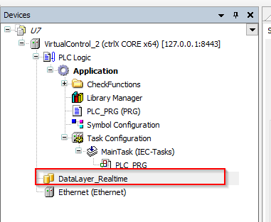
DataLayer_Realtime configuration
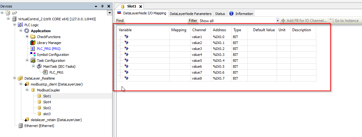
Open your CtrlX PLC Engineering,and Double Click the DataLayer_ReadTime Object.
Refresh to update the connection.
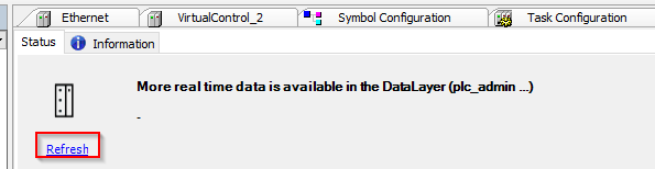
In the Available read-time data of the Data Layer field, you can see all the nodes that ara available to access.

Insert all data again
You can right click the DataLayer_Realtime>Install all data from ctrlX CORE again to arrange all nodes from DataLayer to your PLC Runtime.
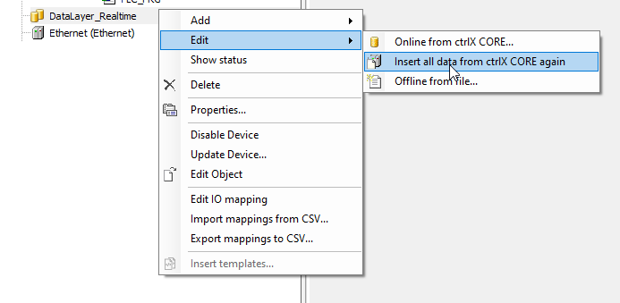
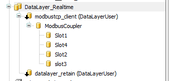
Node From Modbus TCP Client Apps are installed in your Runtime.
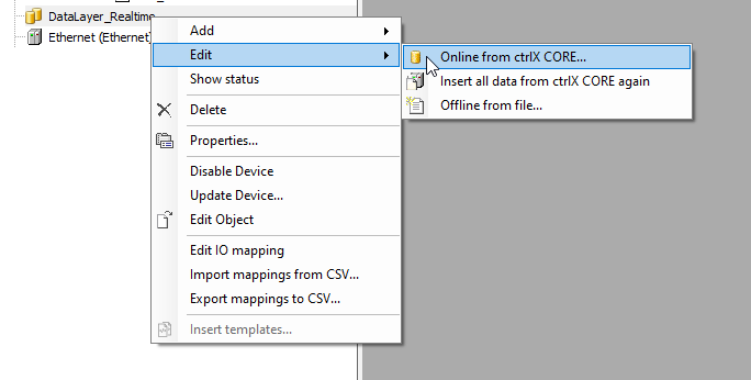
Online from ctrlX CORE
Also, you can direct select which nodes that would be installed in your runtime by Right Click>Online from ctrlX CORE.
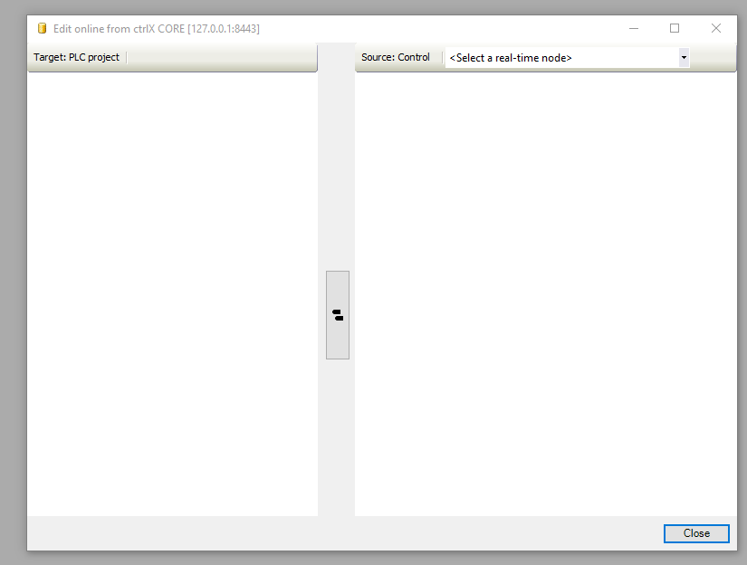
The edit screen is shown.
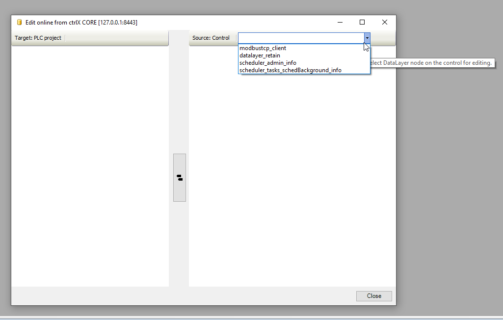
Select the topics that you would like to install in your runtime.
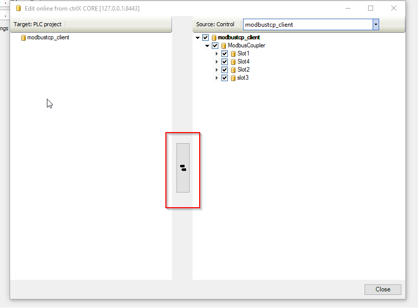
In my tutorial, All Nodes from Modbus TCP Apps is installed.

Press this button to transfer the setting.
Done!

DUT
DUT_8BitChannel
Here is the data type for 8bit Channel.
| TYPE DUT_8BitChannel : STRUCT Ch0,Ch1,Ch2,Ch3,Ch4,Ch5,Ch6,Ch7:BIT; END_STRUCT END_TYPE |
GVL
Create a GVL for the Data mapping.

| {attribute ‘qualified_only’} VAR_GLOBAL Slot1:DUT_8BitChannel; Slot2:WORD; Slot3:ARRAY[0..7]OF WORD; Slot4:ARRAY[0..3]OF WORD; END_VAR |
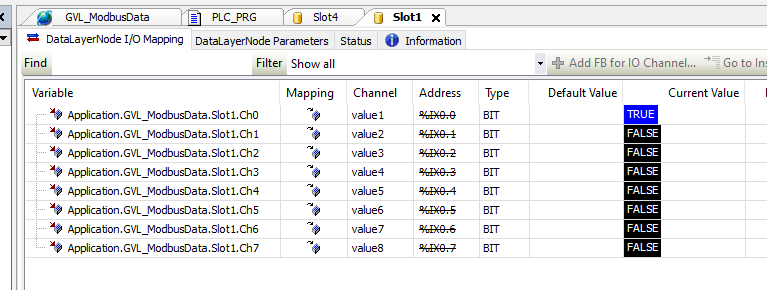
Mapping
Open each item in your DataLayer – now you can map the signal to your user program just like Codesys.
For example, you can press the … button.
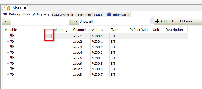
Go to the Text Search tab, and search the tags that you need to be mapped.

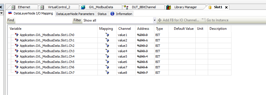
Done!
MAIN
Finally, you need to use these variables in your user program.
| PROGRAM PLC_PRG VAR Slot1:DUT_8BitChannel; Slot2:WORD; Slot3:ARRAY[0..7]OF WORD; Slot4:ARRAY[0..3]OF WORD; END_VAR Slot1:=GVL_ModbusData.Slot1; GVL_ModbusData.Slot2:=Slot2; GVL_ModbusData.Slot3:=Slot3; Slot4:=GVL_ModbusData.Slot4; |
Result
After you login your project to runtime, you can see all items in the data layer are in “green”.

And you would monitor any change of Slot1,Slo4, and also you can modify the output of slot2,slot3.